
How to Select a Reduction Gearbox for Electric Motor
i = motor speed ÷ required output speed. Confirm the gearbox rated output torque is at least the load torque multiplied by a service factor (1.0–2.5 depending on shock and duty), and that the motor can actually drive it (output ≈ motor torque × i × efficiency). The flange and shaft must physically mate: a larger gearbox frame will not bolt to a smaller motor without an adapter. Match the gearbox type to the duty (helical/planetary for efficiency, worm for self-locking, bevel for right-angle).Contents
- What “Selecting a Gearbox for a Motor” Means
- How Motor–Gearbox Matching Works
- Gearbox Type Comparison for a Given Motor
- Engineering Data You Need From the Motor
- Best Applications and Typical Matches
- Step-by-Step Selection — Worked Example
- Common Engineering Mistakes
- Troubleshooting Table
- FAQ
- Why Choose Greensky for Matched Packages
What “Selecting a Gearbox for a Motor” Means
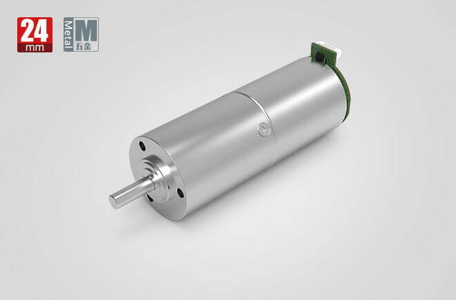 Most gearbox buying guides start from the load: “I have a conveyor that needs 60 rpm and 120 N·m, what reducer do I buy?” This article takes the opposite, equally common, starting point — you already chose the electric motor, and now you need a reduction gearbox that bolts onto it and delivers the speed and torque your machine needs. That single fact changes the whole workflow.
When the motor is fixed, three constraints dominate the choice:
- The mechanical interface is fixed. The motor flange pattern (B5 or B14), bolt circle, shaft diameter and shaft type decide which gearboxes can even be mounted. This is the first gate, decided before any torque math.
- The motor’s rated torque and speed cap the output. No matter how large the gearbox, the maximum usable output torque is the motor torque multiplied by the ratio and the gearbox efficiency. The gearbox cannot create torque the motor does not have.
- The motor type sets the matching rules. A 50 Hz three-phase induction motor, a brushless DC motor, a servo and a brushed DC motor each impose different inertia, commutation and control requirements on the gearbox.
This is distinct from our speed-reducer motor selection guide, which treats the geared motor as a single purchased assembly chosen from the load. Here the motor is given; we match the gearbox to it. For the broader types of speed reducers and the gearbox overview (pillar page), see those references.
How Motor–Gearbox Matching Works
A reduction gearbox is a speed-and-torque transformer. It trades rotational speed for torque while absorbing a small efficiency loss. Matching one to a motor is a three-step physical check.
The mechanical interface (flange, shaft, coupling)
The gearbox input must accept the motor’s shaft. In practice this means:
- Flange pattern. IEC motors use B5 (flange with threaded holes, no feet) or B14 (smaller flange with a spigot). The gearbox input flange must match the same pattern and bolt circle. Dimensions follow IEC 60034-1 and the IEC 60072 mounting series. See our note on motor flange dimensions.
- Shaft diameter and keyway. The gearbox input bore is sized for a shaft range (e.g. 14–19 mm). If the motor shaft is 19 mm, the gearbox must accept 19 mm directly or via the supplied collar/spigot. A mismatch here is a hard stop.
- Output side. The output shaft, hollow shaft or flange must fit the machine — and must carry the overhung (radial) and axial loads the machine applies (see the overhung-load rule in the geared-motor guide).
Torque and speed transformation
The two governing equations are simple:
- Reduction ratio:
i = n₀ / n_out(motor speed ÷ required output speed) - Output torque (theoretical):
T_out = T₀ × i × η(motor rated torque × ratio × gearbox efficiency) - Output power:
P_out = (T_out × n_out) / 9.55(withTin N·m,nin rpm,Pin W)
The gearbox rated output torque must be at least the load torque multiplied by a service factor. But the output you can ever reach is still bounded by T₀ × i × η. If the motor cannot supply enough torque after transformation, a bigger gearbox frame will not help — you must change the motor or the ratio.
Inertia reflection (servo and high-dynamic drives)
For servo and stepper systems the gearbox also transforms inertia. The load inertia seen by the motor is reduced by the square of the ratio:
- Reflected load inertia:
J_reflected = J_load / i² - Inertia ratio:
J_ratio = J_reflected / J_motor_rotor
Keep J_ratio at 5:1 or below (3:1 for precision positioning) so the servo stays tunable. This is why a servo matched with the wrong ratio either hunts or needs a far larger motor; the precision planetary gearbox page covers the servo case in depth.
Gearbox Type Comparison for a Given Motor
Once the interface fits and the torque is known, pick the gearbox type by duty. The table below maps motor + application to the right reduction principle.
| Gearbox type | Typical efficiency | Backlash | Best matched to | Watch-outs |
|---|---|---|---|---|
| Helical / in-line (parallel shaft) | 94–97% | Medium (8–20 arcmin) | 3-phase induction & BLDC on conveyors, mixers, general machinery | Needs axial space; not right-angle |
| Precision planetary | 90–97% | Low (3–10 arcmin, ≤1 arcmin available) | Servo / stepper on CNC, robots, automation | Higher cost; see harmonic vs. planetary |
| Worm (right-angle) | 50–90% (drops with ratio) | High (10–30 arcmin) | Lifting, hoists, self-locking needs | Heat at high ratio; see worm gearbox guide |
| Bevel / spiral bevel (right-angle) | 88–95% | Medium | Right-angle drives, agitators, conveyors needing 90° turn | Higher cost than worm at low ratio |
| Cycloidal | 85–93% | Low–medium | Heavy shock, frequent reversal, aggregate equipment | Bulky; see cycloidal reducer |
| Micro gearbox | 65–85% (miniature) | Low–medium | Small 24 V BLDC / stepper in locks, instruments | Torque and frame limited by size |
Right-angle vs. in-line. If the motor shaft must turn the load 90°, choose worm, bevel or right-angle planetary. If space permits an in-line train, helical or planetary give the best efficiency and the lowest heat.
Engineering Data You Need From the Motor
Before sizing, pull these from the motor nameplate and datasheet. They are the inputs to every formula below.
Torque and power formulas
| Quantity | Formula | Notes |
|---|---|---|
| Motor rated torque | T₀ = 9550 × P / n | P in kW, n in rpm, T in N·m |
| Reduction ratio | i = n₀ / n_out | Round to a standard catalogue ratio |
| Theoretical output torque | T_out = T₀ × i × η | Upper bound set by the motor |
| Required gearbox rating | T_rated ≥ T_load × SF | Service factor SF from duty |
| Reflected inertia | J_reflected = J_load / i² | Servo tuning gate |
Efficiency by gearbox type and ratio
Efficiency falls as the ratio climbs because more stages are needed. A single-stage helical at 5:1 is ~97%; the same principle at 60:1 needs two stages and drops to ~92%. Worm units fall hardest — a 60:1 worm may be only 55% efficient, which is why they run hot under continuous duty. For a broader efficiency discussion tied to motor efficiency classes, see that guide. The efficiency you assume directly changes the torque the motor must supply and the heat the gearbox must shed.
Service factor table
| Load type | Duty | Service factor (SF) | Example machines |
|---|---|---|---|
| Uniform | < 8 h/day, no shock | 1.0–1.25 | Fans, light conveyors, centrifugal pumps |
| Moderate shock | 8–16 h/day | 1.25–1.75 | Belt conveyors with impact, packaging |
| Heavy shock | 16–24 h/day or frequent reversal | 1.75–2.5 | Mixers, crushers, hoists, agitators |
These bands follow the AGMA duty classification (uniform / moderate / heavy shock) and match the ranges used by drive engineers; the gearbox catalogue then lists the rated torque for a given SF. Always multiply before comparing to the rated torque, never after.
Thermal and insulation limits
The motor winding insulation class (per IEC 60034-1) sets how hot the motor can run: Class B = 130 °C, F = 155 °C, H = 180 °C. The gearbox has its own thermal ceiling from lubricant and bearing limits — continuous S1 duty at high ratio can push oil above 80 °C and accelerate breakdown. Size for the thermal rating under the real duty cycle, not just the peak mechanical torque.
Best Applications and Typical Matches
| Application | Typical motor | Matched gearbox | Why |
|---|---|---|---|
| Belt / roller conveyor | 0.37–3 kW 3-phase induction | Helical in-line | High efficiency, continuous duty, low cost |
| CNC axis / robotics | Servo or BLDC | Precision planetary | Low backlash, high torsional stiffness, inertia match |
| Hoist / lift / gate | Brake motor, 3-phase | Worm or brake-gear | Self-locking, right-angle, holds load on power loss |
| Planetary mixer / agitator | 1.5–7.5 kW 3-phase | Helical-bevel or heavy helical | Handles shock, vertical shaft, thrust rating |
| Micro actuator / instrument | 24 V BLDC / stepper | Micro gearbox | Sub-30 mm envelope, low inertia |
| Rehab / assistive robot | Coreless BLDC | Planetary + strain-wave | Compact, near-zero backlash, see DC motor for rehab robots |
Step-by-Step Selection — Worked Example
Given motor: a 1.5 kW 4-pole 3-phase induction motor, 1400 rpm, IEC 90 frame, B14 flange, 24 mm shaft. Machine: a packed-belt conveyor needing 60 rpm output and 90 N·m load, running 16 h/day with moderate impact.
Step 1 — Motor rated torque
T₀ = 9550 × 1.5 / 1400 = 10.23 N·m
Step 2 — Reduction ratio
i = 1400 / 60 = 23.3 → pick the nearest standard ratio, 24:1. Actual output speed = 1400 / 24 = 58.3 rpm (close enough to 60 rpm).
Step 3 — Required gearbox rating (service factor)
Moderate shock, 16 h/day → SF = 1.5. Required rated torque: 90 × 1.5 = 135 N·m. The gearbox must be rated at ≥ 135 N·m.
Step 4 — Check the motor can actually drive it
For a helical unit, η ≈ 0.95. Theoretical output: T_out = 10.23 × 24 × 0.95 = 233 N·m. This comfortably exceeds the 135 N·m requirement — the motor has headroom, and a size-90 helical gearbox rated ~200 N·m is the right frame.
Step 5 — Mechanical interface
IEC 90 / B14 flange with a 24 mm shaft. Select a gearbox whose input flange matches B14 and whose input bore covers 24 mm. A size-110 gearbox (140 mm input flange) would not bolt directly to an IEC 90 motor — an adapter would be required, which is why frame size tracks motor frame size.
Step 6 — Overhung load
The conveyor sprocket applies a radial load at the output shaft. Confirm P_radial ≤ the gearbox catalogue overhung-load rating at 58 rpm. If exceeded, move the support bearing outward or pick the next frame size.
Step 7 — Thermal / duty check
Continuous S1 at 16 h/day: verify the gearbox continuous-rated torque (not peak) ≥ 135 N·m and that oil temperature stays within limits. Output power P_out = (135 × 58.3) / 9550 = 0.82 kW, well within the 1.5 kW motor.
| Parameter | Value | Decision |
|---|---|---|
| Motor torque T₀ | 10.23 N·m | From nameplate |
| Ratio i | 24:1 | Standard, n_out ≈ 58 rpm |
| Required rating | ≥ 135 N·m | Load 90 × SF 1.5 |
| Motor-driven output | 233 N·m | 10.23 × 24 × 0.95 |
| Chosen gearbox | Size-90 helical, 200 N·m | Fits B14 / 24 mm shaft |
Common Engineering Mistakes
- Sizing torque but ignoring the flange. Engineers solve the torque math, then discover the chosen frame will not bolt to the motor. Check the B5/B14 pattern and shaft diameter first.
- Assuming a bigger gearbox gives more torque. Output is capped by
T₀ × i × η. Oversizing the frame beyond the motor’s capability only adds inertia and cost. - Using the rated torque instead of peak for servo. Acceleration and shock loads draw peak motor torque; size the gearbox against peak (with SF), or it will pit and spall in weeks.
- Forgetting inertia matching. On servo systems a poor ratio makes
J_ratioexceed 5:1, causing hunting and long settling. UseJ_load / i²to pick the ratio, not just torque. - Confusing mechanical and thermal ratings. A worm unit that passes the torque check can still overheat in continuous duty because 40–50% of input power becomes heat. Verify the thermal rating.
- Skipping the overhung load. A sprocket or pinion on the output stub applies a radial force; exceeding the catalogue limit destroys the output bearing. Compute it before ordering.
Troubleshooting Table
| Problem | Likely cause | Solution |
|---|---|---|
| Gearbox will not bolt to motor | Flange pattern or shaft mismatch (B5 vs B14, wrong bore) | Match flange; use correct input bore or an adapter collar; verify per IEC 60034-1 mounting |
| Output torque too low | Ratio too small or motor under-sized | Increase ratio (more stages) or upsize the motor; torque is capped at T₀ × i × η |
| Worm gearmotor overheating | Low efficiency; continuous high-ratio duty | Check thermal rating, not just torque; switch to helical/planetary or improve cooling |
| Servo hunts / won’t settle | Inertia mismatch (J_ratio > 5:1) | Raise ratio to cut reflected inertia, or pick a motor with higher rotor inertia |
| Output bearing fails early | Overhung load exceeds rating | Add outboard bearing; pick next frame size; respect radial-load limit |
| Premature gear pitting | Service factor too low for shock duty | Apply correct SF (1.75–2.5 for heavy shock) per AGMA duty class |
FAQ
How do I match a gearbox to an existing motor?
Read four numbers from the motor nameplate: rated torque, rated speed, flange pattern and shaft diameter. Compute ratio i = motor speed / required output speed, then confirm the gearbox rated output torque is at least load torque times the service factor, and that the motor can actually drive it (motor torque × i × efficiency). Finally check the flange and shaft fit the gearbox input.
What flange and shaft sizes must match between motor and gearbox?
The gearbox input flange must share the motor’s flange pattern (B5/B14), bolt-circle diameter and shaft diameter (within the gearbox input bore range, using the supplied spigot/collar). A larger gearbox frame cannot bolt directly onto a smaller motor without an adapter, so the mechanical interface is the first gate, before torque.
Can a bigger gearbox make my motor produce more torque?
No. The gearbox only transforms what the motor already produces. Maximum usable output torque is capped at motor torque × ratio × efficiency. Oversizing the gearbox frame beyond what the motor can drive adds inertia and cost but yields no extra torque.
What service factor should I use for a gearbox?
Use 1.0–1.25 for smooth uniform loads running under 8 h/day, 1.25–1.75 for moderate shock, and 1.75–2.5 for heavy shock or continuous 24 h duty. Multiply the required output torque by the factor before comparing against the gearbox rated torque.
How does gearbox ratio affect servo inertia matching?
The gearbox reduces the load inertia seen by the motor by the square of the ratio: J_reflected = J_load / i². A larger ratio makes a heavy load look lighter to the motor; aim for a reflected-inertia-to-rotor ratio of 5:1 or less, or 3:1 for high-precision positioning.
Why is my worm gearmotor overheating even though the torque calculation passed?
Worm stages are 50–90% efficient, so a large share of input power becomes heat instead of output. A unit that passes the torque check can still exceed its thermal rating under continuous duty. Verify the thermal/continuous-duty rating, not just the mechanical torque rating, and consider a higher-efficiency type if duty is long.
Why Choose Greensky for Matched Motor–Gearbox Packages
Greensky Power designs and manufactures custom electric motors and complete OEM actuator assemblies, so we treat the motor and the reduction gearbox as one matched system rather than two parts bought separately. For your program we supply:
- Standard and custom 24 V BLDC, BLDC, brushed DC and servo motors with IEC B5/B14 flanges and verified shaft dimensions.
- Helical, planetary, worm, cycloidal and micro gearboxes with matched input flanges and documented rated-torque, efficiency and backlash data.
- Pre-validated motor–gearbox pairs with the ratio, service factor and inertia checked before shipment — removing the flange-mismatch and thermal surprises described above.
- Engineering support for industrial motor selection and torque calculation.
Related Technical Resources
- Gearbox overview (pillar page)
- Speed-reducer motor selection guide
- Different types of speed reducers
- Precision planetary gearbox deep dive
- Worm gearbox selection guide
- Cycloidal reducer guide
- Harmonic drive vs. planetary gear
- Micro gearboxes explained
- Brushless DC motor (BLDC) basics
- 24 V brushless DC motor parameters
- Servo motor fundamentals
- Brushed DC motor overview
- BLDC vs. servo motor comparison
- What is the use of a DC geared motor?
- DC motor for rehabilitation robots
- Motor flange dimensions
- How to calculate motor torque
- Motor efficiency classes
- Selecting a motor for industrial use
- Motor controller guide
- Direct-drive vs. gear-motor
- DC motors category
- Custom electric motors
- OEM motor program
References and Standards
- IEC 60034-1:2022 — Rotating electrical machines, general requirements (insulation & temperature classes, mounting). webstore.iec.ch/en/publication/65446
- IEC 60034-30-1 — Efficiency classes of line-operated AC motors. webstore.iec.ch/publication/91195
- ANSI/NEMA MG 1-2021 — Motors and Generators (definitions, service conditions, ratings). webstore.ansi.org/standards/nema/ansinemamg2021
- NEMA — Motor and generator product guidance. nema.org/products/pages/motor-and-generator.aspx
- U.S. DOE — Motor systems efficiency and load guidance. energy.gov — 10097517.pdf
- IEA — Electric motors and industrial efficiency. iea.org/energy-system/industry/electric-motors
- AGMA — Gear rating and service-factor methodology (uniform / moderate / heavy shock). agma.org
- SKF — Bearing failures and their causes (overhung load, misalignment). skf.com — bearing failures
- Siemens — SIMOTICS electric motors product range. siemens.com — electric motors
- IEEE Xplore — Peer-reviewed motor / actuator design paper. ieeexplore.ieee.org/document/6342334
- maxon — EC technology and gearhead selection. maxongroup.com — ec-technology
- FAULHABER — Brushless DC motors and micro-drive know-how. faulhaber.com — brushless DC motors
- Yaskawa — Motion and servo system technical downloads. yaskawa.com/downloads/search-index
- Tsubaki — Gearmotor selection technical reference (service-factor method). tsubakimoto.co.jp — selection reference
This article was prepared by the Greensky Power engineering team as a practical selection reference. Standards and manufacturer documents are linked for verification; always confirm the latest edition and the motor/gearbox nameplate before finalizing a design.
