
All About Servo Motors Basics: How They Work, Types Compared & Sizing
[ez-toc]
What Is a Servo Motor?
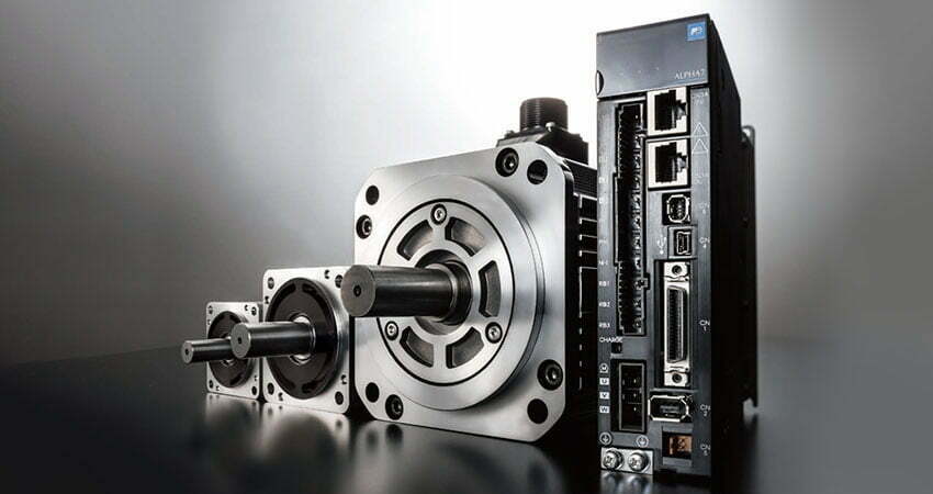
A servo motor is the moving element of a servomechanism — a control system built on the principle of closed-loop feedback. The word comes from the Latin servus (slave): the motor obeys a master command (position, speed, or torque) and the system constantly checks whether it actually did. A servo is therefore not defined by its construction (AC, DC, brushed, brushless, rotary, or linear) but by the loop around it.
In practice a servo system has three elements, and a bare motor is useless without the other two:
- The motor — converts electrical power into mechanical torque and motion.
- The feedback device — an encoder, resolver, or tachometer that reports actual position/speed/velocity to the drive.
- The drive (amplifier/controller) — compares the command with the feedback and adjusts current to the motor. See our motor controller and drive overview for how the drive closes the loop.
This is the single fact that separates a servo from a plain BLDC or brushed DC motor: those are motors; a servo is a motor plus feedback plus a correcting drive. For the broader motor landscape, start with our electric motor basics guide.
How a Servo Motor Works (Step by Step)
The loop runs thousands of times per second. Using a positioning move as the example:
1. The controller issues a command
A PLC or motion controller sends a target — a position, a speed, or a torque — to the servo drive. In a modern digital system this is a numeric setpoint, not an analog voltage.
2. The drive energizes the motor
The drive outputs the three-phase current (for an AC servo) or commutated DC needed to push the rotor. For AC servo, field-oriented control (FOC) keeps the stator field at ~90° to the rotor magnets, maximizing torque per amp.
3. The rotor moves
In an AC servo the rotating stator field drags the permanent-magnet rotor; rotor speed tracks the field frequency.
4. The feedback device reports the truth
An encoder (incremental or absolute) or resolver measures the actual shaft angle and speed and sends it back. Encoder line count sets the position resolution: a 20-bit absolute encoder resolves a full turn into roughly 1,048,576 steps.
5. The drive compares and corrects
The drive subtracts feedback from command to get the error signal. While error remains, it keeps driving; when error reaches zero the motor holds. This is why a servo can hold a load against disturbance — it is always correcting.
6. Nested control loops
A real servo stacks three loops, each feeding the next: a current/torque loop (fastest, sets motor torque), a velocity loop, and a position loop (outermost). Tuning these gains is the art of servo commissioning. Our 48 V BLDC drive article covers a compact drive implementation.
Servo vs Stepper vs Induction — Comparison Tables
The most common buying question is “servo or something cheaper?” The tables below are the decision aids we give customers.
Servo vs stepper vs standard induction motor
| Criterion | Servo motor | Stepper motor | AC induction (fixed/VFD) |
|---|---|---|---|
| Control loop | Closed (encoder/resolver) | Open loop | Open or VFD speed loop |
| Position accuracy | Encoder-limited, ±1 count | Step angle (e.g. 1.8°) | Low without feedback |
| Top speed | High (3000-6000 rpm common) | Low (few hundred rpm usefully) | Mid; high with VFD |
| Dynamic response | Excellent (high accel) | Fair; resonates at high step rate | Poor for start-stop |
| Stall behavior | Holds torque, drive limits current | Loses steps if overloaded | Runs, draws high current |
| Cost | Highest (motor + drive + encoder) | Lowest | Low-Mid |
| Best when | Precise, fast, varying load | Low-speed, stable load | Constant-speed, no positioning |
For a deeper stepper comparison, see our stepper motor guide. When the job is steady running at one or two speeds, a plain motor with a reducer is usually more cost-effective than a servo.
AC servo vs DC servo
| Criterion | AC servo (PMSM) | DC servo (brushed) | DC servo (brushless) |
|---|---|---|---|
| Commutation | Electronic, 3-phase inverter | Mechanical brushes | Electronic (like AC) |
| Maintenance | None (no brushes) | Brush replacement | None |
| Speed range | Very wide | Limited by commutation | Wide |
| Power density | High | Moderate | High |
| Typical use | Industrial robots, CNC | Legacy / low-cost | Battery, medical, aerospace |
Because an AC servo is essentially a brushless motor with feedback and a drive, the motor technology overlaps heavily with our BLDC basics page; the difference is the resolver/encoder and the servo tuning.
Feedback device selection
| Device | Resolution | Robustness | Use |
|---|---|---|---|
| Incremental encoder | High (up to 20+ bit) | Good | General automation |
| Absolute encoder | High, retains position | Good | Safety, no homing needed |
| Resolver | Moderate (analog) | Excellent (heat/vibration) | Military, oil & gas, EV |
| Tachometer | Velocity only | Good | Velocity loop only |
Engineering Data: Efficiency, Temperature, Torque & Inertia
Key formulas
| Quantity | Formula | Notes |
|---|---|---|
| Shaft power | P[kW] = T[N·m] × n[rpm] / 9550 | Also P[W] = T × ω[rad/s], ω = 2πn/60 |
| Acceleration torque | T = J × α | J = inertia [kg·m²], α = angular accel [rad/s²] |
| RMS torque (thermal) | Trms = √(Σ Ti² × ti / Σ ti) | Must stay under continuous rating |
| Reflected inertia via gear | Jref = Jload / N² | N = gear ratio; inertia drops by N² |
Efficiency and IE class
The servo motor is rated to IEC 60034-30-1 like any other machine (typically IE3 or IE4 for a modern permanent-magnet design). The drive is covered by IEC 61800. The reason servo systems look efficient in the field is operational: a servo draws only the current the load demands, so a partially loaded axis wastes little, whereas a fixed-speed motor draws roughly constant magnetizing current regardless of load. For the efficiency-class logic, see our efficiency class explainer.
| IE class | Relative loss | Typical servo use |
|---|---|---|
| IE3 | Baseline | Standard industrial servo motors |
| IE4 | ~20% less loss than IE3 | Premium PMSM servo |
| IE5 | ~40% less loss than IE3 | SynRM / ultra-premium (rare in servo) |
Temperature limits
Two independent ceilings apply, and engineers often forget the second:
| Component | Limit | Standard |
|---|---|---|
| Winding insulation | Class F 155°C, Class H 180°C | IEC 60034-1 |
| Permanent magnets (NdFeB) | 80°C (N/M), up to ~200°C (UH/EH grade) | Magnet grade data |
| Bearings | ~80°C practical ceiling | SKF bearing guidance |
In practice the bearing, not the winding, fails first — keep bearing temperature near or below 80°C and derate at high ambient or altitude. Our industrial motor selection guide covers derating.
Inertia matching — the part most guides skip
The inertia ratio is load inertia (referred to the motor shaft) divided by motor rotor inertia. A widely used rule of thumb keeps this below 10:1 for stable tuning without exotic gains. Above that, the loop becomes hard to tune, overshoot grows, and the motor “fights” the load. A gearbox reduces referred inertia by the square of the ratio, so a 7:1 gearbox cuts referred load inertia by 49× — often the cheapest way to fix a bad ratio. Compare approaches in our direct-drive vs gear-motor article.
Best Applications for Servo Motors
Servos earn their cost where precision, speed, and disturbance rejection matter:
- Industrial robots and CNC — multi-axis positioning with tight path accuracy.
- Packaging and pick-and-place — fast start-stop, high cycle rates.
- Semiconductor and electronics assembly — micron-level repeatability.
- Printing and textile — synchronized web/speed control.
- Medical and lab automation — quiet, clean, brushless operation (see BLDC for medical).
- AGV and mobile equipment — battery-fed brushless servo with regen.
For low-speed high-torque axes, a geared motor or a servo with an integrated gearbox is the standard answer.
Step-by-Step Servo Sizing (Worked Example)
Sizing from horsepower alone is the most common mistake we see. Work the loads in order.
Step 1 — Define the motion profile
A machine-tool X-axis must move a 40 kg table 0.2 m in 0.4 s, then dwell, then return. Peak speed 3000 rpm at the motor; friction + cutting force equivalent to 1.5 N·m; move repeats every 2.0 s.
Step 2 — Compute load inertia and refer it to the motor
Assume a coupling/ball-screw such that the load inertia referred to the motor shaft is Jload = 0.05 kg·m².
Step 3 — Peak torque (acceleration + process)
Required angular acceleration to hit 3000 rpm (314 rad/s) in ~0.15 s is roughly α ≈ 314 / 0.15 ≈ 2090 rad/s². With total inertia Jtotal ≈ 0.06 kg·m²:
Tacc = J × α = 0.06 × 2090 ≈ 125 N·m. Add process torque 1.5 N·m → Tpeak ≈ 127 N·m (within the motor’s short-time rating).
Step 4 — RMS (continuous) torque for thermal rating
Over the 2.0 s cycle the motor accelerates (high torque, 0.15 s), dwells at holding torque, and returns. Computing Trms = √(Σ T²t / Σ t) gives roughly Trms ≈ 36 N·m. The motor’s continuous rating must exceed this, not its peak.
Step 5 — Speed and power
At 3000 rpm and Trms 36 N·m: P = T × n / 9550 = 36 × 3000 / 9550 ≈ 11.3 kW. The drive and cabling are sized to this continuous power plus the peak current.
Step 6 — Check the inertia ratio
If the candidate motor has rotor inertia Jm = 0.008 kg·m², the ratio is 0.05 / 0.008 = 6.25:1 — acceptable, no gearbox needed. Had Jm been 0.0008, the ratio would be 62:1 and we would add a 7:1 servo gearbox: referred inertia drops to 0.05 / 49 ≈ 0.00102, ratio ≈ 1.3:1, and a far smaller/cheaper motor suffices.
The counterintuitive insight
Bigger is not better. Oversizing the motor to “be safe” worsens the inertia ratio, makes tuning harder, increases cost and footprint, and may still deliver worse dynamic performance than a correctly sized motor behind a gearbox. Size to the RMS torque and the inertia ratio, then let the gearbox do the rest. For the torque arithmetic, see how to calculate motor torque; for the full reducer-inclusive method, see speed-reducer motor selection.
Common Engineering Mistakes
- Sizing from horsepower only. Peak and RMS torque and the inertia ratio decide the motor; power is a downstream consequence. A 15 kW motor can be the wrong choice for a 5 kW average load if its rotor inertia is too low.
- Ignoring the inertia ratio. A 20:1 or 60:1 ratio will not tune cleanly no matter how good the drive is. Fix it mechanically (gearbox) before touching gains.
- Oversizing “for safety.” See above — it backfires on dynamics and cost.
- Treating AC servo speed as proportional to voltage. AC servo speed is set by drive frequency under FOC, not by line voltage. Voltage scales torque capability, not speed.
- Assuming a stepper and a servo are interchangeable. They are not; losing steps is acceptable in some jobs and catastrophic in others. Use the comparison table, not habit.
- Forgetting bearing temperature. Winding class F/H lets engineers assume 150°C is fine; the bearing fails at ~80°C.
- Believing a servo “cannot be opened.” Servo motors are routinely serviced; the encoder is the delicate part — never disassemble the encoder end without recalibration. The motor itself is rebuildable.
- No derating for ambient/altitude. Both insulation and bearing life shorten above 40°C or at altitude; apply the factor before specifying.
Troubleshooting Table (Problem → Cause → Solution)
| Problem | Likely cause | Solution |
|---|---|---|
| Oscillation / hunting at setpoint | Gain too high; bad inertia ratio; mechanical resonance; noisy encoder | Lower proportional gain; add gearbox to fix ratio; stiffen coupling; replace encoder; re-tune drive |
| Position error accumulates | Encoder fault; slip; wrong homing | Verify encoder signal; check coupling; re-home; replace feedback device |
| Overheating / thermal trip | Sustained overload; poor ventilation; high ambient; wrong RMS sizing | Re-size to Trms; improve cooling; derate; check duty cycle |
| Excessive audible noise | PWM switching frequency; resonance; loose mechanics | Raise switching freq if supported; damp resonance; tighten/balance load |
| Drive overcurrent fault | Short; locked rotor; incorrect motor parameters | Check windings; free the shaft; load correct motor data into drive |
| Loss of holding torque under load | Load torque exceeds rating; supply sag | Re-size; verify bus voltage; use gearbox to multiply torque |
Frequently Asked Questions
What is the difference between a servo motor and a stepper motor?
A servo motor closes a feedback loop with an encoder or resolver and drives torque to a commanded position, velocity, or torque; a stepper motor moves in open-loop increments with no feedback. Servos give higher speed, better dynamic response, and feedback-based accuracy but cost more and need a drive. Steppers are cheaper, simpler, and fine for low-speed, moderate-accuracy positioning where losing a step is not catastrophic.
Is an AC servo motor brushless?
Nearly all modern AC servo motors are brushless permanent-magnet synchronous machines (PMSM) driven by a three-phase inverter with field-oriented control. The absence of brushes removes a wear item and is why AC servo has largely replaced DC servo in industrial use. DC servo motors are brushed or brushless; the brushless DC variant shares the same commutation electronics as an AC servo.
How do you size a servo motor?
Size by three loads: peak torque (acceleration plus friction plus cutting/process torque, within the motor’s short-time rating), RMS or continuous torque over the duty cycle (for thermal rating), and speed at the required torque (with P = T × n / 9550 in kW). Then check the inertia ratio: for a directly coupled load the load inertia referred to the motor shaft should not exceed roughly 10× the motor rotor inertia, or add a gearbox to bring it down and improve tuning.
What efficiency class are servo motors?
The servo motor itself is typically IE3 or IE4 when rated to IEC 60034-30-1, and the drive is governed by IEC 61800. A servo system is efficient in practice because it draws only the current the load commands, unlike a fixed-speed motor that runs at full power whether or not the load needs it. System-level efficiency is addressed by IEC 61800-9.
Why does my servo oscillate or hunt around the setpoint?
Oscillation is usually a tuning or mechanical problem: too high a proportional gain, a resonant mechanical linkage, excessive load-to-motor inertia ratio, or a coarse/degraded encoder giving noisy position feedback. Lower the gain, stiffen the mechanical coupling, add a gearbox to correct the inertia ratio, or replace the encoder. Always verify the feedback signal before changing loop gains.
Can a servo motor run at high temperature?
The motor winding is limited by its insulation class (IEC 60034-1 class F ~155°C, class H ~180°C) and the permanent magnets by their grade (NdFeB loses flux above about 80-200°C depending on grade). The bearing, not the winding, often fails first: keep the bearing temperature around or below 80°C per SKF guidance. Derating at high ambient or altitude is mandatory.
Do I need a gearbox with a servo motor?
Not always. A gearbox trades speed for torque and, just as important for servo performance, divides the reflected load inertia by the square of the ratio, which fixes a bad inertia ratio and lets a smaller, cheaper motor do the job. For high-torque low-speed axes and for matching a light motor to a heavy load, a servo gearbox is the standard solution.
Why Choose Greensky for Servo and Motion Systems
- Motor + drive + gearbox as one validated system. We supply and tune the combination so the inertia ratio and torque match at the interface — no three-vendor finger-pointing. Pair our BLDC servo-grade motors with our controllers and 48 V drives.
- Full motor family. BLDC, brushed DC, AC, and geared versions — the recommendation follows the calculation, not the catalogue.
- Custom shafts, flanges, connectors, and ratios. Through custom motor development and OEM/ODM programmes — usually faster than forcing a standard part to fit. See our flange guide for mounting options.
- Engineering support, not just parts. We run the sizing math with you — peak torque, RMS, speed, and inertia ratio — so the servo you receive is right the first time.
References and Standards
This article was reviewed by the Greensky Power engineering team against the following authoritative sources. Links verified August 2026.
- IEC 60034-1:2022 — Rotating electrical machines, general requirements (insulation classes, temperature). webstore.iec.ch/en/publication/65446
- IEC 60034-30-1 — Efficiency classes of AC motors (IE1-IE5). webstore.iec.ch/publication/91195
- IEC 61800 — Adjustable speed electrical power drive systems (servo drive efficiency and safety). webstore.iec.ch
- ANSI/NEMA MG 1 — Motors and Generators standard. webstore.ansi.org/standards/nema/ansinemamg2021
- NEMA — Motor and generator product guidance. nema.org/products/pages/motor-and-generator.aspx
- U.S. DOE — Motor systems efficiency and load guidance. energy.gov/sites/prod/files/2014/04/f15/10097517.pdf
- IEA — Electric motors and industrial efficiency. iea.org/energy-system/industry/electric-motors
- SKF — Bearing failures and their causes (temperature limits). skf.com/group/support/bearing-failures-and-their-causes
- Siemens — SIMOTICS electric motors. siemens.com/global/en/products/drives/electric-motors.html
- IEEE Xplore — Servo control and motor drive research. ieeexplore.ieee.org/document/6342334
- maxon — DC/EC motor and gear technology white papers. maxongroup.com
- Faulhaber — Drive and motion control know-how. faulhaber.com/en/know-how
- Yaskawa — Servo motor and motion technical resources. yaskawa.com/downloads/search-index
- ADVANCED Motion Controls — Servo motor fundamentals. a-m-c.com/servomotor
- Kollmorgen — How servo motors work (loop architecture). kollmorgen.com/en-us/blogs/how-servo-motors-work
Related technical resources:
- Brushless DC motor range and specifications
- Brushed DC motors — when they are still the right choice
- Stepper motor guide
- Motor controllers and drives
- How to calculate motor torque
- Speed-reducer motor selection
- Different types of speed reducers compared
- Direct drive motor vs gear motor
- BLDC basics: commutation, Kv, and sizing
- Electric motor basics: types and selection
