
Dc motor robot-What motor for rehabilitation robot?
- What Is a DC Motor for a Rehabilitation Robot?
- Why Rehabilitation Robots Demand Specialized Motors
- How a Rehab-Robot Actuator Works
- DC Motor Types Compared for Rehab Robots
- Engineering Data: Joint Torque, Efficiency and Temperature
- Best Applications for Rehab-Robot DC Motors
- Step-by-Step Motor Selection for a Rehab Robot
- Common Engineering Mistakes
- Troubleshooting
- FAQ
What Is a DC Motor for a Rehabilitation Robot?
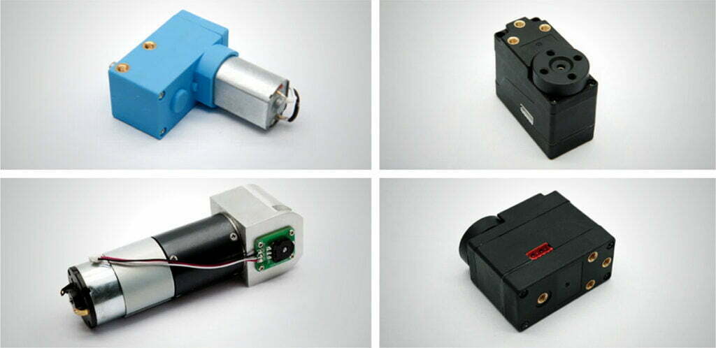
A rehabilitation robot is a medical device that assists, guides, or resists a patient’s limb movement during therapy — think lower-limb exoskeletons for stroke gait training, upper-limb rehab arms, hand-and-finger trainers, and gait assisters. The actuator that moves each joint is the heart of the machine, and in the vast majority of modern designs that actuator is a small brushless DC motor (BLDC) integrated with a gearbox, an encoder, and a servo drive.
The term “DC motor for rehabilitation robot” therefore rarely means a bare motor. It means a servo actuator assembly: a prime mover plus reduction gearing plus feedback plus a safety path, tuned for human-interactive force. Unlike an industrial robot arm that moves a payload, a rehab actuator must be compliant, quiet, and safe to fail while in contact with a frail limb. That single difference drives every specification below.
For context on the prime mover itself, see our electric motor basics, the 24 V brushless DC motor parameters guide, and the servo motor fundamentals that underpin closed-loop rehab actuators.
Why Rehabilitation Robots Demand Specialized Motors
Generic automation motors are optimized for throughput. Rehab actuators are optimized for the human in the loop, which creates four non-negotiable requirements:
- Torque density. The actuator is worn or mounted beside the patient, so every gram matters. Literature on lower-limb exoskeletons ranks specific power (power per unit mass) as the top selection criterion. A 24 V BLDC of 100 W massing under 400 g is typical for a hip or knee joint.
- Low cogging / low torque ripple. A stepper or a slotted motor with visible cogging feels “notchy” through the limb and can trigger spasticity. Slotless or coreless BLDC motors remove this.
- Quiet running. Therapy happens in clinics and homes; acoustic noise above ~40 dB is clinically objectionable. Brush commutation and gear whine are both eliminated by BLDC + helical or harmonic gearing.
- Medical-grade safety. The system falls under ISO 13485 quality controls and IEC 60601-1 safety, which pushes designers toward redundant sensing, electromagnetic brakes, and insulated, sealed construction.
These demands are why a bare brushed DC motor — cheap and simple as it is — is increasingly reserved for low-cost gait trainers rather than patient-borne exoskeletons, where motor efficiency classes and sealed flange-mounted construction decide clinical uptime.
How a Rehab-Robot Actuator Works (Step by Step)
A single joint actuator is a closed loop. The sequence below is what actually happens when a knee joint assists a step:
- Command. The therapy controller computes a target joint torque or angle from a gait model.
- Drive. A servo drive sends current to the BLDC using field-oriented control (FOC), reading the motor’s Hall sensors for commutation. See our motor controller guide for the drive side.
- Reduction. The high motor speed (thousands of rpm) is stepped down by the gearbox (planetary or harmonic) to the low joint speed (tens of rpm) while multiplying torque.
- Feedback. An encoder on the output shaft reports actual joint position and velocity; a torque sensor or motor-current estimate closes the loop.
- Safety. A watchdog monitors for runaway; an electromagnetic brake holds the joint if power is lost, preventing the patient’s leg from collapsing.
For the gearing half of this loop, see our gearbox overview, the harmonic vs. planetary comparison, and the broader speed-reducer motor selection guide.
DC Motor Types Compared for Rehab Robots
Five motor families appear in rehab-robot designs. Their trade-offs are stark:
| Type | Continuous efficiency | Cogging / ripple | Control complexity | Life | Best rehab use |
|---|---|---|---|---|---|
| Brushed DC | 75–80% | Moderate (commutator) | Low (PWM only) | 1,000–3,000 h | Low-cost gait trainers, non-worn assist carts |
| BLDC (slotted) | 85–95% | Low if slotless; some if slotted | Medium (FOC + Hall) | 10,000+ h | General hip/knee exoskeleton joints |
| Coreless / hollow-cup BLDC | 80–90% | Near zero | Medium | 10,000+ h | Hand, wrist, finger rehab; delicate assistance |
| Servo (frameless BLDC + encoder) | 90–98% | Very low | High (closed loop) | 10,000+ h | High-authority hip/knee joint actuators |
| Stepper | 40–60% (runs hot) | High (detent) | Low (open loop) | Good (no brushes) | Rare; fixed, low-dynamics supports only |
The fuller technology split is in our BLDC vs. servo comparison and the servo motor deep dive. For wearable joints, BLDC or servo is the default; for finger-scale dexterity, coreless BLDC is the specialist choice — exactly the segment Faulhaber and Maxon dominate, and which our precision planetary gearbox program supports.
Engineering Data: Joint Torque, Efficiency and Temperature
Per-joint torque requirements
Biomechanics studies give joint torque per unit body mass during walking. Scaling to a 75–90 kg adult, and converting to the assisted torque a rehab device typically supplies, yields the planning ranges below. The published pediatric figures (hip 0.7, knee 0.5, ankle 1.2 N·m/kg) and the H2 exoskeleton (35 N·m continuous hip from a 24 V / 100 W BLDC + 160:1 harmonic) anchor the numbers.
| Joint | Body-mass torque factor | Typical continuous (assisted) | Peak | Joint speed | Preferred motor |
|---|---|---|---|---|---|
| Hip | 0.7 N·m/kg | 25–35 N·m | 70–180 N·m | 30–60 rpm | Frameless servo / BLDC |
| Knee | 0.5 N·m/kg | 20–30 N·m | 45–90 N·m | 40–90 rpm | BLDC + harmonic/planetary |
| Ankle | 1.2 N·m/kg | 20–36 N·m | 60–120 N·m | 50–120 rpm | Flat BLDC + harmonic |
| Shoulder / elbow | — | 3–10 N·m | 6–20 N·m | 100–300 rpm | Coreless BLDC |
| Wrist / finger | — | 0.2–1.5 N·m | 0.4–3 N·m | 300–600 rpm | Micro coreless BLDC |
Efficiency by motor type
| Motor | Typical efficiency | Battery impact |
|---|---|---|
| Brushed DC | 75–80% | Moderate drain, brush loss |
| BLDC | 85–95% | Excellent — key for untethered use |
| Servo (PMSM-based) | 90–98% | Best, but higher electronics overhead |
| Stepper | 40–60% | Poor — continuous current even at hold |
Temperature and insulation limits
Motor winding insulation is classified by IEC 60034-1 (which adopts the IEC 60085 temperature classes):
| Insulation class | Max winding temp | Rehab use note |
|---|---|---|
| Class B | 130 °C | Adequate for intermittent therapy cycles |
| Class F | 155 °C | Recommended — sealed enclosures run hot |
| Class H | 180 °C | High-duty or passive-cooled shells |
Rehab actuators are often sealed against cleaning fluids and worn close to the body, so the effective thermal ceiling is lower than the nameplate. Size for Class F with a 20–30 °C margin and add a thermal cutoff. Bearing life — see SKF bearing failure modes — also degrades above 80 °C, so keep gearbox grease within its rated band.
Torque and power formulas
Use these to move from a joint requirement to a motor specification:
- Output torque:
T_out = T₀ × i × η(motor torque × ratio × gearbox efficiency) - Output power:
P = (T_out × n_out) / 9.55(withTin N·m,nin rpm,Pin W) - Required ratio:
i = n₀ / n_outand alsoi = T_out / (T₀ × η) - Input current at supply
V:I = P_in / V, whereP_in = P_shaft / η_motor - Biomechanical joint torque estimate:
T_joint ≈ F × r(segment weight × moment arm)
These relations assume a geared actuator. Where direct drive is possible, weigh the direct-drive vs. gear-motor trade-off; for most rehab joints the reduction is unavoidable. Efficiency planning also ties back to IE efficiency classes.
For the motor-side math, see the torque calculation guide.
Best Applications for Rehab-Robot DC Motors
- Lower-limb exoskeletons (stroke, SCI gait training): high-torque hip/knee/ankle actuators, 24 V BLDC + 50:1–160:1 harmonic or planetary reduction. Real devices use 100–150 W motors at each joint.
- Upper-limb rehab arms: shoulder/elbow assistance with coreless BLDC for low inertia and smooth assist; DC geared motors keep the form factor small, while planetary gear-motor applications cover the gripper end.
- Hand and finger trainers: micro coreless BLDC in the 10–30 W range, paired with micro gearboxes for fingertip force control.
- Gait and balance trainers (treadmill-mounted): higher continuous duty, often flat BLDC gear motors for low profile; worm gearboxes suit self-locking supports and cycloidal reducers suit high-shock frames.
- Pediatric exoskeletons: extremely weight-sensitive; 24 V EC-flat BLDC + strain-wave gearing, ratios split per joint (knee ~50:1, ankle ~120:1 in published builds). Compare options in our speed-reducer types guide.
Step-by-Step Motor Selection for a Rehab Robot
Follow this order so the motor, not the catalogue, sets the specification.
- Define the joint load. Estimate required continuous and peak torque from body mass and moment arm (use the per-joint table above). Add a 20–30% safety margin for friction and voltage droop.
- Fix the output speed. Read the joint’s peak angular velocity from the gait model (knee swing ≈ 60–90 rpm).
- Pick a gearbox type. Harmonic for hip/knee (compact, near-zero backlash); planetary for wrist/gripper (shock-resistant, cheaper); see different types of speed reducers and the industrial motor selection guide.
- Choose the ratio. Set
i = T_out / (T₀ × η)so the motor runs inside its continuous torque at the required speed. Verify motor speedn₀ = i × n_outstays below the bearing/iron-loss limit (typically < 8,000–10,000 rpm for a 24 V unit). - Check power and current. Compute
P_out, divide by gearbox and motor efficiency forP_in, thenI = P_in / V. Confirm the battery and driver can sustain it. - Add safety. Specify an electromagnetic brake, redundant encoder, and thermal cutoff; confirm the build meets IEC 60601-1.
Worked example: knee actuator for a 90 kg patient
Requirement. Assisted knee actuator: continuous T_out = 25 N·m, peak 50 N·m, output speed n_out = 60 rpm, 24 V supply.
Step 4 — ratio. Choose a 32 mm BLDC with continuous torque T₀ = 0.30 N·m and gearbox efficiency η = 0.85:
i = 25 / (0.30 × 0.85) = 98:1 → select 100:1
Motor speed n₀ = 100 × 60 = 6,000 rpm — comfortably inside the limit.
Step 5 — power and current.
P_out = (25 × 60) / 9.55 = 157 W
P_shaft = 157 / 0.85 = 185 W; P_in = 185 / 0.85 = 218 W
I = 218 / 24 = 9.1 A
Peak motor torque needed: 50 / (100 × 0.85) = 0.59 N·m — within a 2× overload of the 0.30 N·m continuous rating.
T₀ = 0.08 N·m would need i = 25 / (0.08 × 0.85) = 368:1, forcing n₀ = 22,000 rpm — past the bearing and iron-loss ceiling, where efficiency collapses and the gearbox input fails. A larger frame at a moderate ~100:1 ratio beats a tiny motor at 350:1. Ratio is not free; it trades motor speed for reliability.Common Engineering Mistakes
- Sizing from motor power, not joint torque. A 100 W motor at the wrong ratio delivers either too little torque or an unusable speed. Start from
T_out. - Ignoring backlash in the force loop. A 3° gearbox plus an encoder on the motor side means the limb feels lost motion. Mount the encoder on the output and prefer ≤ 1° (harmonic) for hip/knee.
- Underestimating thermal margin. Sealed, body-worn actuators run hotter than bench tests. A Class B winding with no margin trips mid-session.
- Choosing steppers for dynamics. Open-loop steppers skip steps under variable patient load and dissipate heat continuously — poor for interactive therapy.
- Forgetting the safety brake. Without a holding brake, a power loss drops the patient’s limb. This is a medical, not cosmetic, requirement.
- Battery voltage droop. A 24 V pack sagging to 20 V cuts torque 17%. Size the pack for end-of-discharge voltage, not nominal.
Troubleshooting: Problem → Cause → Solution
| Problem | Likely cause | Solution |
|---|---|---|
| Joint feels notchy / jerky | Cogging torque or high gearbox backlash | Switch to slotless/coreless BLDC; use harmonic gearing; move encoder to output shaft |
| Motor overheats in 10–15 min | Undersized for duty; poor thermal path | Increase frame size or ratio; use Class F; add conduction plate to exoskeleton frame |
| Patient limb drops on power loss | No holding brake | Add electromagnetic brake sized for peak joint torque |
| Torque sags as battery drains | Pack sagging below motor’s usable voltage | Size pack for end-of-discharge V; raise supply to 24–48 V; add DC-DC regulation |
| Encoder loses position after restart | Incremental encoder, no home reference | Use absolute encoder or add a homing routine on power-up |
| Gearbox whines at low speed | Spur stages, insufficient mesh quality | Use helical or harmonic stages; verify bearing preload |
Frequently Asked Questions
What type of motor is used in rehabilitation robots?
Most powered exoskeletons and rehab robots use brushless DC (BLDC) motors coupled to a high-ratio gearbox (planetary or harmonic). Coreless BLDC motors are preferred for delicate hand and wrist rehab because of near-zero cogging, while frameless servo motors are common in hip and knee joint actuators.
Why are brushless DC motors preferred over brushed motors in exoskeletons?
BLDC motors run at 85–95% efficiency, have no commutator to wear out, produce less EMI, and support tens of thousands of hours of continuous duty — all critical for a battery-powered wearable device carried next to a patient.
How much torque does a rehab robot joint need?
Biomechanics studies report knee torque around 0.5 N·m per kg of body mass during walking. For a 90 kg patient that implies a peak knee torque near 45 N·m; assisted gait trainers typically target 20–30 N·m continuous with 2× peak headroom.
Which gearbox is best for a rehab robot joint?
Harmonic (strain-wave) drives give the highest ratio in the shortest length with near-zero backlash, ideal for hip and knee joints. Planetary gearheads are cheaper, robust against shock, and better for grippers and wrists. Worm gears self-lock but waste 30–60% of input power as heat.
What voltage is typical for rehabilitation robot motors?
24 V DC is the de facto standard for wearable rehab robots because it stays below the 60 V SELV safety limit, pairs with mature lithium-polymer batteries, and keeps cabling light. Some desktop rehab devices use 12 V; high-power exoskeletons may use 48 V.
What safety standards apply to rehab robot motors?
The actuator sits inside a medical electrical device, so IEC 60601-1 (general safety) and ISO 13485 (quality management) govern the system, while the motor itself follows IEC 60034-1 for insulation and temperature classes. Many OEMs add an electromagnetic brake and redundant position sensing for patient safety.
Why Choose Greensky for Rehab-Robot Motors?
Greensky Power develops custom electric motors and OEM actuator assemblies for medical and assistive robotics. Our rehab-robot program covers:
- BLDC and coreless platforms from 8 mm to 60 mm diameter, 12 V / 24 V / 48 V, with slotless windings for low cogging in hand and wrist trainers.
- Integrated reduction — planetary, harmonic, and flat gear-motor options with backlash down to ≤ 1° for smooth force control.
- Encoder-ready shafts and brake provisions to shorten your safety qualification under IEC 60601-1.
- Documentation for submission — torque/speed curves, thermal derating, and insulation-class data aligned to IEC 60034-1.
Explore the DC motors category or contact our engineering team for a joint-specific sizing review.
Related Resources
- Gearbox overview
- Brushless DC motor (BLDC) basics
- 24 V brushless DC motor parameters
- Servo motor fundamentals
- Brushed DC motor overview
- BLDC vs. servo motor comparison
- What is the use of a DC geared motor?
- Micro gearboxes explained
- Precision planetary gearbox deep dive
- Harmonic drive vs. planetary gear
- Different types of speed reducers
- Speed-reducer motor selection guide
- How to calculate motor torque
- Motor controller guide
- BLDC flat gear motor
- Direct-drive vs. gear-motor
- Selecting a motor for industrial use
- Motor efficiency classes
- Motor flange dimensions
- Custom electric motors
- OEM motor program
References
- IEC 60034-1:2022 — Rotating electrical machines, general requirements (insulation & temperature classes). webstore.iec.ch/en/publication/65446
- IEC 60034-30-1 — Efficiency classes of line-operated AC motors. webstore.iec.ch/publication/91195
- IEC 60601-1 — Medical electrical equipment, general safety (via IEC 60601 collection). iec-60601 medical electrical equipment
- ISO 13485 — Medical devices — Quality management systems. iso.org/iso-13485-medical-devices.html
- ANSI/NEMA MG 1 — Motors and Generators standard. webstore.ansi.org/standards/nema/ansinemamg2021
- NEMA — Motor and Generator product resources. nema.org/products/pages/motor-and-generator.aspx
- U.S. DOE — Motor energy efficiency and system optimization. energy.gov — motor systems
- IEA — Electric motors and drives (energy system). iea.org — electric motors
- SKF — Bearing failures and their causes. skf.com — bearing failures
- Siemens — SIMOTICS electric motors. siemens.com — electric motors
- IEEE Xplore — Peer-reviewed micro-motor / actuator design paper. ieeexplore.ieee.org/document/6342334
- Maxon — EC (external-rotor brushless) motor technology. maxongroup.com — ec-technology
- Faulhaber — Brushless DC motors for medical applications. faulhaber.com — brushless DC motors
- Bortole et al., “The H2 robotic exoskeleton for gait rehabilitation after stroke.” J NeuroEngineering Rehabil (2015). pmc.ncbi.nlm.nih.gov/articles/PMC4469252
- MDPI Sensors (2023) — Single-leg exoskeleton with 24 V BLDC + strain-wave gearing for children with cerebral palsy. mdpi.com/1424-8220/23/13/6103
This guide is written by the Greensky Power engineering team for designers and procurement engineers building rehabilitation and assistive robots. Specifications are planning ranges; validate every actuator against your device’s IEC 60601-1 risk file and clinical requirements.
