
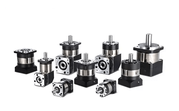
Selection of Speed Reducer Motor: A Step-by-Step Engineering Guide
Quick Answer:Selecting a speed reducer motor means matching four things in order: the required output speed (which sets the reduction ratio), the load torque corrected by a service factor (which sets the frame size), the gearbox efficiency (which sets the motor power), and the mechanical and thermal limits — overhung load, duty cycle, and ambient temperature. Calculate the ratio as i = n_motor ÷ n_output, then multiply measured load torque by a service factor of 1.0–1.6 depending on shock and daily running hours. Choose the gear type last, based on whether you need efficiency (helical), torque density (planetary), self-locking (worm), or shock tolerance (cycloidal). Selecting on nameplate power alone is the single most common cause of premature gearbox failure.
[ez-toc]
Most speed reducer motor selections go wrong at the very first step, and it is almost always the same mistake: the buyer starts from the motor power they already have, then looks for a gearbox to bolt onto it. The correct sequence runs the other way. The load defines the output speed and torque; those define the ratio and the gearbox frame; the gearbox efficiency then defines the motor. Reverse that order and you end up with either an overheating worm unit or a 0.75 kW motor doing 0.1 kW of work.
This guide sets out the calculation chain we use when sizing units for OEM customers, including the correction factors that catalogue pages tend to bury in an appendix. If you first need to understand the mechanical differences between gear families, read different types of speed reducers — this page assumes you already know roughly which family you are looking at and focuses on getting the numbers right.
What Is a Speed Reducer Motor?
A speed reducer motor is a single assembly that combines an electric motor with a gear reduction unit in one housing or one bolted stack. The motor supplies high-speed, low-torque rotation; the reducer trades that speed for torque at a fixed ratio. The terms gearmotor, geared motor, gear reducer motor and speed reducer motor all describe the same product — the naming varies by region and by supplier catalogue, not by function.
The two governing relationships are simple and worth committing to memory:
n_out = n_motor ÷ i — output speed falls by the ratio
T_out = T_motor × i × η — output torque rises by the ratio, reduced by efficiency
Efficiency η is the term that ruins otherwise sound calculations. It is not a fixed number; it depends on gear type, ratio, load level and temperature, and it compounds across stages. A worm unit quoted at “up to 90%” may deliver 45% at the ratio you actually ordered. More on that in the engineering data section below.
Speed Reducer Motor vs. Separate Motor and Gearbox
An integrated gearmotor shares a single shaft and bearing set between motor and reducer, which removes the coupling, the alignment tolerance and one set of bearings. A separately mounted motor and gearbox gives you flexibility to change either component but introduces alignment error, coupling backlash and a longer overall package. For volume OEM builds the integrated unit is almost always the correct choice; for large industrial drives where the motor may be rewound or swapped, separate units still make sense. Where no reduction is needed at all, compare with a direct drive motor.
How Speed Reducer Motor Selection Works
Selection is a chain of dependent calculations. Each step feeds the next, and skipping one means the later steps are built on a guess.
- Define the driven machine’s requirement. Not the motor’s — the machine’s. Linear speed, drum or pulley diameter, mass to be moved, friction coefficient, and how many hours per day it runs. For a rotating load, the required output speed in rpm. This is the only input that comes from outside the drivetrain.
- Convert to output speed and load torque. Linear speed becomes rpm through the drum geometry; mass and friction become a tangential force, and that force at the drum radius becomes torque. Efficiency losses in chains, belts or screws between the reducer and the load are divided out here, not later. Detailed torque arithmetic is covered in how to calculate motor torque.
- Apply the service factor. The torque the machine needs while running steadily is not the torque the gearbox must survive. Starts, reversals, shock loads and long daily running hours all consume gear and bearing life. Multiply by the service factor from the table below to get the design torque the gearbox must be rated for.
- Fix the reduction ratio. Divide the motor’s rated speed by the required output speed. Catalogue ratios come in steps, so you will land on the nearest available value and accept a small speed deviation — typically ±3% is fine, more than ±5% usually means revisiting the drum diameter or using a variable frequency drive.
- Select the frame from design torque, then back-calculate motor power. Pick the gearbox size whose rated output torque exceeds your design torque at the chosen ratio. Only now compute motor power, using the actual efficiency at that ratio:
P_motor = T_out × n_out ÷ (9550 × η). - Verify the mechanical limits. Overhung (radial) load at the sprocket or pulley, axial load, shaft diameter, keyway, and the flange pattern. A unit that passes on torque routinely fails on overhung load, especially with chain or toothed-belt drives. See what a motor flange is for the mounting dimensions that matter.
- Verify the thermal limits. Continuous duty at high ambient temperature, or a high starting frequency, can force a larger frame than torque alone would suggest. Gearboxes have a separate thermal rating from their mechanical rating, and small sealed units rely entirely on case radiation.
Reducer Type Selection Matrix
Choose the gear family after you know the numbers, not before. This matrix maps the requirement that usually dominates the decision onto the type that satisfies it. Full mechanism descriptions are on the gearbox overview.
| Reducer Type | Efficiency per Stage | Typical Ratio Range | Backlash | Select It When | Avoid It When |
|---|---|---|---|---|---|
| Spur | 95–98% | 3:1 – 10:1 | 30–60 arcmin | Cost is the priority, load is steady, noise is not critical | Quiet operation or high speed is required |
| Helical | 96–98% | 5:1 – 300:1 (multi-stage) | 15–30 arcmin | Continuous industrial duty, efficiency and low noise both matter | Right-angle layout or self-locking is required |
| Bevel / Helical-bevel | 94–97% | 5:1 – 200:1 | 15–30 arcmin | Right-angle drive needed but worm efficiency is unacceptable | Budget is tight — costs more than worm for the same ratio |
| Planetary | 95–97% | 3:1 – 100:1 (to 1000:1 multi-stage) | 3–15 arcmin | Torque density and coaxial packaging matter; servo and robotics duty | Cost per unit torque is the deciding factor |
| Worm | 45–90% (ratio dependent) | 5:1 – 100:1 single stage | 20–60 arcmin | Self-locking is required, or a high ratio in one right-angle stage | Duty is continuous and energy cost matters |
| Cycloidal | 85–93% | 10:1 – 120:1 | <3 arcmin | Shock loading is severe — mixers, crushers, presses | Very high input speed or lowest cost is required |
| Harmonic (strain wave) | 75–90% | 50:1 – 320:1 | <1 arcmin | Zero-backlash positioning in minimum volume and mass | Impact loads are present or budget is limited |
Two pairings come up in nearly every enquiry: spur vs planetary and planetary vs worm. For sub-40 mm frames, see micro gearboxes; for high-precision positioning, harmonic vs planetary and the cycloidal reducer page cover the trade-offs in detail.
Engineering Data Required Before You Select
Torque and Power Formulas
Metric: T (N·m) = 9550 × P (kW) ÷ n (rpm)
Imperial: T (lb·in) = 63025 × HP ÷ n (rpm)
Output speed from linear speed: n (rpm) = V (m/min) × 1000 ÷ (π × D (mm))
Motor power from output requirement: P_motor (kW) = T_out (N·m) × n_out (rpm) ÷ (9550 × η)
Efficiency by Type and Ratio
Efficiency multiplies across stages. Two helical stages at 97% give 94% overall; two worm stages at 70% give 49%. The worm case is where most sizing errors hide, because catalogue headline figures are quoted at low ratios where worm efficiency is at its best.
| Single-Stage Worm Ratio | Typical Efficiency | Self-Locking? | Power Lost as Heat (1 kW input) |
|---|---|---|---|
| 5:1 | ~90% | No | 100 W |
| 10:1 | ~85% | No | 150 W |
| 20:1 | ~75% | Marginal | 250 W |
| 40:1 | ~65% | Yes | 350 W |
| 60:1 | ~55% | Yes | 450 W |
| 100:1 | ~45% | Yes | 550 W |
Those heat figures are not academic. A 100:1 worm unit passing 1 kW dumps roughly 550 W into a sealed aluminium case. If the case cannot radiate that, the oil temperature climbs until the lubricant film fails. Motor-side efficiency matters too — see motor efficiency class and the IE classification in IEC 60034-30-1.
Service Factor Table
The service factor corrects rated torque for real duty. Take the value from the load character and daily running hours, then apply the corrections below it.
| Load Character | Examples | ≤3 h/day | 3–10 h/day | >10 h/day |
|---|---|---|---|---|
| Uniform | Belt conveyors, fans, centrifugal pumps | 1.00 | 1.10 | 1.25 |
| Moderate shock | Chain conveyors, mixers, packaging machines | 1.10 | 1.25 | 1.40 |
| Heavy shock | Crushers, presses, hoists, reversing drives | 1.25 | 1.40 | 1.60 |
Additional corrections, applied multiplicatively:
- More than 10 starts per hour: × 1.1; more than 60 starts per hour: × 1.3 (and check permitted starting frequency against the load inertia ratio).
- Ambient above 40 °C: × 1.2. Ambient below −20 °C: × 1.2 (lubricant viscosity at start-up).
- High load inertia relative to motor inertia (ratio > 5): × 1.2, and verify the permitted starting frequency separately.
Overhung Load Check
When a sprocket, gear or pulley is mounted on the output shaft, the resulting radial force must stay inside the permitted overhung load (OHL) for that unit:
OHL (N) = 2000 × T (N·m) × f × Lf ÷ Dpcd (mm)
where f = drive coefficient — chain 1.0, toothed belt 1.25, gear 1.25, V-belt 1.5 — and Lf = position factor, 1.0 at mid-shaft, rising to 2.0 at the shaft end.
Small pulleys generate large radial loads. Halving the pitch circle diameter doubles the overhung load. When a unit fails the OHL check, increasing the sprocket PCD is usually cheaper than moving up a frame size.
Thermal and Insulation Limits
IEC 60034-1 defines permitted temperature rise by insulation class, measured above a 40 °C reference ambient. Exceeding the class limit does not cause instant failure — it halves winding life for roughly every 10 °C of sustained overshoot.
| Insulation Class | Max Winding Temp | Permitted Rise (40 °C ambient) | Typical Use |
|---|---|---|---|
| A | 105 °C | 60 K | Legacy / light duty |
| E | 120 °C | 75 K | Appliance motors |
| B | 130 °C | 80 K | General industrial |
| F | 155 °C | 105 K | Standard for modern gearmotors |
| H | 180 °C | 125 K | High ambient, frequent starts |
Gearbox lubricant has its own ceiling, independent of the winding: mineral gear oil is generally limited to a 90–95 °C sump temperature, synthetic PAO extends that to about 105–110 °C, and grease-packed sealed units are typically capped near 80 °C. Bearing life is equally temperature-sensitive; SKF’s failure-mode documentation is the standard reference for diagnosing what went wrong when it does.
Duty Cycle Classification
IEC 60034-1 duty types describe the load pattern over time, and they change the required frame size:
- S1 — Continuous. Constant load long enough to reach thermal equilibrium. Size on rated torque and thermal capacity.
- S2 — Short-time. Load for a defined period, then cooling to ambient. Permits a smaller frame than S1 for the same torque.
- S3 — Intermittent periodic. Load/rest cycles without reaching equilibrium; specified as a cyclic duration factor (for example S3 40%).
- S4 — Intermittent with starting. As S3 but starting current heating is significant. This is where high-inertia loads force a frame increase.
Best Applications and Their Typical Selections
- Belt and roller conveyors — helical or helical-bevel, ratio 20:1 to 80:1, service factor 1.25. Efficiency dominates because these run continuously. Common in appliance and light industrial production lines.
- AGV and mobile robot drive wheels — planetary with a BLDC motor, ratio 15:1 to 50:1. Torque density and coaxial packaging decide it. Thermal management is the usual failure point; see AGV motor overheating.
- Hoists, gates and inclined conveyors — worm, ratio 40:1 and above for self-locking. Accept the efficiency penalty in exchange for load holding without a brake. Our NMRV worm gearbox range covers the standard catalogue ratios; background on the worm gear reducer page.
- Mixers and agitators — cycloidal or helical-bevel, service factor 1.4 to 1.6 because starting torque in a settled batch can reach three times running torque. See mixer gear motor selection.
- Robotic joints and CNC axes — planetary or harmonic, selected on backlash rather than torque. Detailed cases in precision planetary gearbox applications and planetary gear motor application fields.
- Pumps and HVAC plant — helical, S1 continuous duty, sized with efficiency class as a primary criterion because running hours are high. Relevant to chilled water and cooling pump drives.
- Electric vehicle and e-mobility actuators — compact planetary with EV-grade BLDC motors, often in a flat gear motor format where axial length is constrained.
Step-by-Step Selection Process — With a Worked Example
The abstract method is easier to trust once you see it run. Below is a complete selection for a light belt conveyor, using the following brief:
Design brief
Conveyed mass M = 250 kg · belt speed V = 18 m/min · drive drum diameter D = 250 mm · friction coefficient μ = 0.12 · chain transmission efficiency to drum = 0.95 · 16 hours/day · 12 starts/hour · uniform load with light shock · ambient 30 °C · 4-pole motor at ~1400 rpm
Step 1 — Required Output Speed
n_out = V × 1000 ÷ (π × D) = 18 × 1000 ÷ (π × 250) = 22.9 rpm
Step 2 — Load Torque at the Output Shaft
Tangential force: F = μ × M × g = 0.12 × 250 × 9.81 = 294 N
Torque at drum radius 0.125 m: T = 294 × 0.125 = 36.8 N·m
Divided by the 0.95 chain efficiency: T_load = 36.8 ÷ 0.95 = 38.7 N·m
Step 3 — Apply the Service Factor
Uniform-to-light-shock load, more than 10 h/day → SF = 1.25. Starts exceed 10 per hour → × 1.1.
SF_total = 1.25 × 1.1 = 1.375 → T_design = 38.7 × 1.375 = 53.2 N·m
Step 4 — Reduction Ratio
i = 1400 ÷ 22.9 = 61.1 → nearest catalogue ratio 60:1
Actual output speed: 1400 ÷ 60 = 23.3 rpm, a +1.7% deviation from the 22.9 rpm target. Acceptable.
Step 5 — Frame Size and Motor Power
Select a helical gearmotor frame whose rated output torque at 60:1 exceeds 53.2 N·m. Two helical stages at 96% each give η = 0.96² = 0.92.
P_motor = T_load × n_out ÷ (9550 × η) = 38.7 × 23.3 ÷ (9550 × 0.92) = 0.096 kW
Round up to the next standard frame: 0.18 kW, or 0.25 kW if future capacity increases are expected. Note the gap between calculation and habit — a great many conveyors of this size ship with 0.75 kW motors, running at 13% load, where efficiency and power factor are both poor.
Step 6 — Overhung Load Check
Chain drive, sprocket PCD 100 mm, load acting at mid-shaft (f = 1.0, Lf = 1.0):
OHL = 2000 × 53.2 × 1.0 × 1.0 ÷ 100 = 1064 N
Compare against the catalogue permitted radial load for the chosen frame — typically 1500–1800 N in this size class, so the selection passes. Had the sprocket been 60 mm PCD, OHL would rise to 1773 N and the check would likely fail.
Step 7 — Thermal and Duty Verification
16 h/day at constant load is S1 continuous duty. Ambient 30 °C is below the 40 °C reference, so no derating is required. Class F insulation gives comfortable margin. Confirm the gearbox thermal rating at 60:1 separately from its mechanical rating — for helical units at this power level, thermal capacity is rarely the constraint, but for a worm unit at the same ratio it very often is.
Step 8 — Mechanical Interface and Environment
Confirm output shaft diameter and keyway, mounting position (foot, flange, or hollow-shaft), flange pattern, IP rating for the installation, cable entry orientation, and whether a brake or encoder is needed. If the drive is speed-regulated, verify motor controller compatibility and the minimum continuous speed at which the motor still cools adequately. Broader motor-side criteria are covered in how to select a motor for an industrial application.
Common Engineering Mistakes
- Sizing from motor power instead of load torque. Power is an output of the calculation, not an input. Starting from an available motor guarantees either an oversized drive or a gearbox operating outside its rated torque.
- Ignoring efficiency at the actual ratio. Using a catalogue’s best-case worm efficiency at a 100:1 ratio understates required motor power by more than a factor of two, and understates heat rejection by the same margin.
- Omitting the service factor entirely. A gearbox sized to exactly the running torque will survive steady operation and fail on the first jam, reversal, or cold start. This is the most common cause of tooth fracture we see in returned units.
- Passing the torque check and failing overhung load. Frequent with chain and toothed-belt drives on small sprockets. The gearbox is adequately rated, the output bearing is not, and failure appears as shaft-seal leakage followed by bearing noise within months.
- Treating self-locking as a safety brake. Worm self-locking is static, not dynamic — vibration can back-drive a nominally self-locking pair. Any application where a falling load endangers people needs a real mechanical brake, regardless of gear type.
- Overlooking starting frequency and load inertia. A drive that is thermally fine at 6 starts per hour can overheat at 60. Inertia ratio above about 5:1 also produces impact torque at start that no service factor from a load-character table anticipates.
- Specifying the ratio before confirming the motor’s actual speed. A 4-pole motor is nominally 1500 rpm at 50 Hz but runs near 1400 rpm loaded; using 1500 in the ratio calculation puts output speed 7% low before anything else is considered.
Troubleshooting Table: Problem → Cause → Solution
| Problem | Probable Cause | Solution |
|---|---|---|
| Output speed lower than calculated | Motor slip under load; ratio computed from synchronous rather than rated speed | Recalculate with nameplate rated speed; adjust ratio or add a VFD |
| Gearbox case running above 90 °C | Low-efficiency ratio (worm), thermal rating exceeded, insufficient ventilation | Switch to helical or bevel-helical, upsize frame, add forced cooling, change to synthetic lubricant |
| Motor trips on start, runs fine once moving | Breakaway torque exceeds start capability; high load inertia; cold thick lubricant | Increase service factor, use soft-start or VFD ramp, select low-temperature lubricant |
| Oil leaking from output shaft seal | Overhung load exceeded, shaft deflection, seal wear, overfilled sump | Recheck OHL calculation, increase sprocket PCD or frame size, correct fill level |
| Broken or pitted gear teeth | No service factor applied; repeated shock or reversal loading | Recalculate design torque with correct SF; consider cycloidal for shock duty |
| Excessive backlash / positioning error | Gear type unsuited to positioning duty; wear from load reversals | Move to planetary (3–15 arcmin) or harmonic (<1 arcmin) |
| Torque falls off after months of service | Internal wear, degraded lubricant, motor-side demagnetisation or brush wear | See causes of DC motor torque loss; service lubricant on schedule |
| Bearing noise within first year | Radial overload, misalignment, contamination, inadequate sealing | Verify OHL and alignment; upgrade IP rating; consult SKF failure-mode reference |
| Load creeps down when stopped (worm unit) | Ratio too low for reliable self-locking; vibration back-driving the pair | Increase ratio above 40:1 and fit a mechanical brake — never rely on self-locking alone |
Frequently Asked Questions
How do I calculate the reduction ratio for a speed reducer motor?
Divide the motor’s rated (not synchronous) speed by the required output speed: i = n_motor ÷ n_out. For a 1400 rpm motor driving a 23 rpm output, the ratio is 61:1, so you select the nearest catalogue value of 60:1 and accept the small speed deviation. If the deviation exceeds about 5%, change the drum or pulley diameter, or add a variable frequency drive.
What service factor should I use for a speed reducer motor?
Use 1.0–1.25 for uniform loads such as belt conveyors and centrifugal pumps, 1.25–1.4 for moderate shock such as mixers and packaging machinery, and 1.4–1.6 for heavy shock such as crushers, presses and hoists. Multiply by a further 1.1 above 10 starts per hour, and by 1.2 for ambient temperatures above 40 °C. The corrected value is the torque the gearbox must be rated for, not the torque it sees while running.
Should I select the motor first or the gearbox first?
Neither — select the load requirement first. Determine output speed and load torque from the driven machine, apply the service factor, fix the ratio, then choose the gearbox frame from the corrected torque. Motor power falls out of that calculation last, divided by the actual gearbox efficiency at the selected ratio.
Why is my worm gearmotor overheating when it passed the torque calculation?
Almost certainly because efficiency was taken from a headline catalogue figure rather than the value at your ratio. A 100:1 single-stage worm typically runs near 45% efficiency, meaning over half the input power becomes heat inside a sealed case. Either upsize the frame for thermal capacity, switch to a helical-bevel unit for the same right-angle layout at 94–97%, or add forced cooling.
How much oversizing margin should I build into the selection?
The service factor already contains the correct margin — adding a second arbitrary safety factor on top is how conveyors end up with motors running at 13% load. Beyond the service factor, allow margin only for a defined reason: a planned throughput increase, a known variation in material properties, or a specified overload duty. Chronic oversizing costs efficiency, power factor and money.
Can I keep my existing gearbox and fit a higher-efficiency motor?
Only after rechecking the numbers. Higher-efficiency motors typically have lower slip, so a nominally identical replacement can run 1–3% faster and change the output speed. Starting torque characteristics also differ, which affects the effective service factor at start. Verify rated speed, starting torque and frame dimensions before assuming a drop-in swap.
What is the difference between a gearbox’s mechanical rating and thermal rating?
The mechanical rating is the torque the gear teeth and bearings can transmit. The thermal rating is the continuous power the case can dissipate without the lubricant exceeding its temperature limit. For helical units the mechanical rating usually governs; for worm units at high ratios, and for any unit in high ambient temperature or enclosed spaces, the thermal rating frequently governs and is the reason a “correctly sized” unit still runs hot.
Why Choose Greensky for Speed Reducer Motors
Greensky Power manufactures integrated gearmotors in Shenzhen for OEM customers across automation, mobility, medical and appliance markets. What matters for selection specifically:
- Selection calculations, not catalogue matching. Send us the load brief — mass, speed, geometry, duty hours, starts per hour, ambient — and our engineering team returns a sized selection with the torque, ratio, efficiency, OHL and thermal working shown, so you can audit the arithmetic rather than trust a part number.
- Full type coverage under one supplier. Helical, spur, planetary, worm (NMRV), cycloidal and flat BLDC gear motors, so the type recommendation follows the engineering rather than whatever we happen to stock.
- Matched motor and reducer. BLDC and brushed DC prime movers paired with the correct controller, avoiding the mismatch that occurs when motor, gearbox and drive come from three suppliers.
- Custom ratios and interfaces. Frame sizes from 22 mm to 120 mm, 12 V to 72 V DC, with custom shafts, keyways, flanges and connectors through our custom motor development and OEM/ODM programmes.
- Compliance and documentation. Units built to IEC 60034 requirements with test data supplied on request — temperature rise, efficiency and no-load current — so your own design review has real numbers to work from.
- Sampling before commitment. Prototype quantities on short lead times, so the selection can be validated on the actual machine before a production order is placed.
Related Technical Resources
- Different types of speed reducers — full comparison
- Gearbox overview and type index
- How to calculate motor torque
- How to select a motor for an industrial application
- What is the use of a DC geared motor
- How a planetary gearbox works
- Worm gear reducer — deep dive
- Cycloidal reducer — deep dive
- Harmonic vs planetary gear
- Motor efficiency class explained
- Direct drive motor vs gear motor
- What are micro gearboxes
References and Standards
The temperature-rise limits, duty classifications and efficiency classes cited above are drawn from published international standards and manufacturer engineering documentation. This article was prepared and reviewed by the Greensky Power engineering team; the sources below are the primary references used.
- International Electrotechnical Commission. IEC 60034-1:2022 — Rotating electrical machines: Rating and performance. https://webstore.iec.ch/en/publication/65446
- International Electrotechnical Commission. IEC 60034-30-1:2014 — Efficiency classes of line operated AC motors (IE code). https://webstore.iec.ch/publication/91195
- American National Standards Institute / NEMA. ANSI/NEMA MG 1 — Motors and Generators. https://webstore.ansi.org/standards/nema/ansinemamg2021
- National Electrical Manufacturers Association. Motors and Generators — Product Section. https://www.nema.org/products/pages/motor-and-generator.aspx
- U.S. Department of Energy, Advanced Manufacturing Office. Determining Electric Motor Load and Efficiency. https://www.energy.gov/sites/prod/files/2014/04/f15/10097517.pdf
- International Energy Agency. Electric Motors — Energy System, Industry. https://www.iea.org/energy-system/industry/electric-motors
- SKF Group. Bearing Failures and Their Causes. https://www.skf.com/group/support/bearing-failures-and-their-causes
- Siemens AG. Electric Motors — SIMOTICS Product Documentation. https://www.siemens.com/global/en/products/drives/electric-motors.html
- IEEE Xplore Digital Library. Design and Efficiency Analysis of Geared Electric Drive Systems. https://ieeexplore.ieee.org/document/6342334
- maxon group. Gear Technology — Knowledge and Support Technical Documentation. https://www.maxongroup.com/assets/public/caas/v1/media/112608/data/32bb5bfabd9ce7d852292f275410c997/knowledge-support-support-antriebswissen-kurz-erklaert-gear-download.pdf
- FAULHABER. Know-How: Drive Technology Engineering Resources. https://www.faulhaber.com/en/know-how/
- Yaskawa Electric Corporation. Technical Documentation and Selection Manuals. https://www.yaskawa.com/downloads/search-index
- Tsubakimoto Chain Co. Small Gear Motor Selection — Technical Data: Service Factor, Inertia Ratio and Overhung Load. https://en.tt-net.tsubakimoto.co.jp/tecs/engd/gen/engd_gen_ggm_sry.asp?lang=en
