
24V Brushless DC Motor Parameters and Uses
Quick Answer
A 24V brushless DC (BLDC) motor is an electronically commutated permanent-magnet motor built for a 24-volt DC bus — the industrial-standard low-voltage supply that stays inside the SELV safety envelope. Its core parameters — rated voltage, power, no-load and rated speed, continuous and peak torque, torque constant Kt, back-EMF constant Ke, efficiency, insulation class and IP rating — describe how much mechanical work it delivers and how much current and heat that work costs. At 24V the same power draws roughly twice the current of a 48V design, so wire gauge, controller rating and thermal management decide whether the motor survives, not just the nameplate. Typical 24V BLDC efficiencies run 80–92% for frames above 40 mm and 55–75% for sub-20 mm micro drives, making them the default for AGVs, medical pumps, HVAC actuators, robotics and battery tools where long life and precise speed control matter.
- What Is a 24V Brushless DC Motor?
- How a 24V BLDC Motor Works
- Decoding the Datasheet: Key 24V BLDC Parameters
- 24V BLDC vs Brushed DC, and 12V vs 48V
- Engineering Data: Efficiency, Temperature Limits, Torque Formulas
- Best Applications for 24V BLDC Motors
- How to Select a 24V BLDC Motor: Step-by-Step
- Worked Sizing Example: 24V BLDC for an AGV Drive Wheel
- Common Engineering Mistakes with 24V BLDC Specs
- Troubleshooting: Problem → Cause → Solution
- Why Choose Greensky 24V BLDC Motors?
- Related Resources
- References and Standards
- Frequently Asked Questions
What Is a 24V Brushless DC Motor?
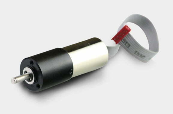
A brushless DC motor replaces the carbon brushes and mechanical commutator of a traditional DC motor with an electronic controller that switches the stator windings in sync with rotor position. In a 24V BLDC the permanent magnets sit on the rotor, the copper windings sit on the stationary stator, and the controller energizes three phases using Hall sensors or back-EMF sensing. The “24V” is the nominal DC bus voltage the motor and its driver are designed around — not a fixed operating point, since a 24V battery or supply swings with load and state of charge.
The 24V class occupies a sweet spot in low-voltage motion. It delivers more torque and current headroom than 12V without the wiring, isolation and controller-cost penalties of 48V or higher. For the theory of how electronic commutation works, see our BLDC basics guide; this page focuses on what every parameter on the datasheet means and where these motors are actually used.
How a 24V BLDC Motor Works
The operating sequence is the same for every BLDC; the 24V rating only sets the voltage scale:
- Rotor sensing. Three Hall-effect sensors (or sensorless back-EMF estimation) report the permanent-magnet rotor angle to the controller.
- Commutation. The controller fires the correct pair of the three phases through MOSFETs so the rotating stator field stays ~90° ahead of the rotor — the condition for maximum torque per amp.
- Torque production. Current in the energized windings interacts with the rotor field to produce torque:
T = Kt × I, where Kt is the torque constant. - Back-EMF generation. As the rotor spins it generates a counter-voltage (back-EMF) proportional to speed:
V_backEMF = Ke × ω. Supply minus back-EMF appears across winding resistance and sets the current. - Closed-loop control. A 6-step or field-oriented control (FOC) algorithm regulates current (torque) and speed, with the 24V bus defining the maximum achievable speed for a given Ke.
Because nothing physically touches except the shaft bearings, a 24V BLDC eliminates brush friction, carbon dust and arcing — the reasons its efficiency and life outclass brushed designs. For high-precision motion the same topology extends into servo motor systems with encoders and FOC.
Decoding the Datasheet: Key 24V BLDC Parameters
Buyers and integration engineers read the same set of parameters on every 24V BLDC datasheet. The table below defines each one, what it tells you, and the typical range for 24V units.
| Parameter | Symbol | What it tells you | Typical 24V BLDC range |
|---|---|---|---|
| Rated (nominal) voltage | Vn | Design bus voltage; sets speed scale via Kv | 24 V DC (tolerance ±10–15%) |
| Rated power | Pn | Sustainable mechanical output | 5 W (micro) – 750 W+ (80–100 mm frame) |
| No-load speed | n0 | Free-run speed at rated voltage, zero load | 3,000–10,000 rpm |
| Rated speed | nn | Speed at the rated operating point | 1,000–6,000 rpm |
| Continuous (rated) torque | Tcont | Torque the motor holds indefinitely within temp limit | 0.02–3 N·m (bare); more with gearbox |
| Peak (stall) torque | Tpk | Maximum short-term torque at stall current | 3–5× continuous |
| Torque constant | Kt | Torque per amp of phase current | 0.02–0.15 N·m/A |
| Back-EMF constant | Ke | Voltage per unit speed (equals Kt in SI) | Ke ≈ Kt |
| Speed constant | Kv | No-load rpm per volt | 100–400 rpm/V |
| Rated current | In | Current at the rated point | 0.5–35 A |
| Winding resistance | R | Line-to-line phase resistance | 0.1–5 Ω |
| Efficiency | η | Mechanical out ÷ electrical in at rated point | 55–92% (see frame-size table) |
| Insulation class | – | Max winding temperature per IEC 60085 | Class B (130°C) to H (180°C) |
| Protection rating | IP | Ingress protection against dust/water | IP40 – IP67 (custom) |
| Rotor inertia | J | Affects acceleration and loop tuning | Listed per model |
A torque calculation crosses directly from load to these values, and the choice between a bare motor and a geared version usually comes down to whether the required torque appears at the motor shaft or at a reduced output speed.
24V BLDC vs Brushed DC, and 12V vs 48V
Brushless vs brushed DC at 24V
The comparison below uses the engineering data competitors typically omit — the figures are consolidated from manufacturer white papers and standards, not marketing copy.
| Factor | 24V Brushless DC (BLDC) | 24V Brushed DC |
|---|---|---|
| Commutation | Electronic (controller + Hall/back-EMF) | Mechanical (brushes + commutator) |
| Typical efficiency | 80–92% (>40 mm frame) | 70–80% |
| Service life | 20,000–40,000 h (bearing-limited) | 2,000–5,000 h (brush-limited) |
| Maintenance | Bearing lubrication only | Regular brush replacement |
| Heat location | Stator (easy to cool) | Rotor (hard to cool) |
| EMI / noise | Low (no arcing) | Higher (brush sparking) |
| Torque at low speed | Strong, consistent with FOC | Drops with brush wear |
| Controller required? | Yes (ESC / BLDC driver) | No (runs on raw DC) |
| Initial cost | Higher (motor + driver) | Lower (motor only) |
The efficiency gap is not cosmetic: a BLDC at 90% vs a brushed motor at 80% drawing the same mechanical power consumes about 11% less electrical energy, which compounds directly into battery runtime on every charge cycle. For the trade-offs when a brushed motor is still acceptable, see our brushed DC motor guide.
Voltage class: 12V vs 24V vs 48V
| Attribute | 12V | 24V | 48V |
|---|---|---|---|
| Current at 200 W | ~16.7 A | ~8.3 A | ~4.2 A |
| Copper loss (I²R) at equal R | 4× baseline | 1× baseline | 0.25× baseline |
| Safety class | SELV | SELV | Still <60 Vdc SELV limit |
| PSU / battery maturity | Ubiquitous (automotive, USB-PD) | Industrial standard | Emerging for high-power |
| Typical power ceiling | <100 W | Up to ~750 W | 750 W – several kW |
| Best fit | Miniature / low-load | AGV, medical, HVAC, robotics | High-torque, long harnesses |
Engineering Data: Efficiency, Temperature Limits, Torque Formulas
Efficiency by frame size
| Frame / type | Typical continuous efficiency | Note |
|---|---|---|
| Sub-20 mm micro BLDC | 55–75% | Fixed losses dominate at low power |
| 42 mm (NEMA 17 class) | 78–88% | Common for robotics, small automation |
| 57 mm (NEMA 23 class) | 82–90% | General-purpose 24V workhorse |
| 80–100 mm | 85–92% | High-power 24V BLDC, often >300 W |
Efficiency classes for line- and inverter-operated machines are standardized in IEC 60034-30-1 and IEC TS 60034-30-2; while those standards target AC induction motors, the same IE thinking applies when you compare BLDC offerings. The U.S. Department of Energy’s motor load and efficiency methodology is the practical reference for measuring real-world performance.
Temperature and insulation limits
| Insulation class (IEC 60085) | Max winding temperature | Typical use in 24V BLDC |
|---|---|---|
| Class B | 130 °C | Standard commercial / industrial |
| Class F | 155 °C | Higher ambient or sealed units |
| Class H | 180 °C | High-duty or high-ambient |
The limiting factor is usually not the magnets but the winding temperature rise above ambient. A 24V BLDC rated for −20 °C to +60 °C ambient still depends on adequate convection or forced air; continuous torque must be de-rated in high ambient or enclosed spaces. Bearing life, the real service-life driver, follows the load/speed/lubrication curve documented by SKF’s bearing-failure reference.
Core formulas
These three equations are enough to move from a load requirement to a motor datasheet:
- Mechanical power from torque and speed:
P[W] = T[N·m] × 2π × n[rpm] / 60, or the handy shortcutP[W] = 9.55 × T × n. - Electrical input:
P_in = P_mech / η, and supply currentI = P_in / V. At 24V this current is what sizes your wires and controller. - Torque and speed constants:
Kt = T / I; in SI unitsKe = Kt; andKv[rpm/V] = 9.549 / Kt[N·m/A]. The no-load speed at the rated bus isn_0 ≈ Kv × V.
Worked datasheet read: a 24V BLDC rated 100 W at 3,000 rpm has continuous torque T = 9.55 × 100 / 3000 = 0.318 N·m. At 85% efficiency it draws I = 100 / (24 × 0.85) = 4.9 A. If its Kt is 0.05 N·m/A, then Kv = 9.549 / 0.05 = 191 rpm/V and no-load speed at 24V is about 4,580 rpm — the 3,000 rpm rated point is roughly 35% speed regulation under load, which is normal.
Best Applications for 24V BLDC Motors
The 24V BLDC dominates applications that need long life, precise speed control and battery or low-voltage bus operation:
- AGVs and mobile robots. Long battery life and smooth low-speed control; pairs with planetary gear motors for wheel drives.
- Medical devices. Pumps, surgical tools and diagnostic drives where low EMI and sealed, maintenance-free operation are mandatory.
- HVAC and building automation. Dampers, small air handlers and fans — see the efficiency case in our chilled-water pump guide.
- Consumer and appliance products. Power tools, air purifiers and smart-home actuators benefit from quiet, brushless operation — see appliance motor applications.
- Electric vehicles and micro-mobility. Hub motors and auxiliary actuators; our EV-grade BLDC motors use higher magnet grades for traction duty.
- Factory automation. Conveyors, CNC auxiliaries and packaging where duty cycles are long and downtime is costly.
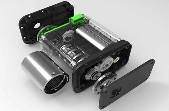
Most of these are torque-rich at low speed, so they end up as a BLDC gear motor rather than a bare shaft — the gearbox moves the operating point into the motor’s efficient band.
How to Select a 24V BLDC Motor: Step-by-Step
- Define the load. Capture required output torque, speed, duty cycle and any overload (startup, incline, jam).
- Add the gearbox first if needed. If output speed < ~500 rpm at the load, a speed reducer almost always yields a smaller, cooler, cheaper system — compare direct drive vs gear motor.
- Compute shaft power. Use
P = 9.55 × T × n; divide by gearbox efficiency to get motor-side power. - Pick the frame. Match motor-side power and torque to a 24V frame from our 24V BLDC selection guide (GPM60 / GPH80 / GPL100 series).
- Check the current.
I = P_in / 24. Confirm the controller rating and wire gauge cover it with margin, especially peak (stall) current. - Verify thermal and environmental limits. Insulation class vs ambient, IP rating vs environment, and bearing life vs load/speed.
- Confirm the interface. Shaft, flange (motor flange), encoder, brake and connector. For non-standard needs, our custom motor development route is usually faster than forcing a catalogue part.
For a broader industrial context, our motor selection for industrial applications guide covers duty cycles and service factors across technologies.
Worked Sizing Example: 24V BLDC for an AGV Drive Wheel
This is the kind of calculation engineers actually run, and the one competitors’ catalog pages skip. We size a 24V BLDC gear motor for a 200 kg AGV with a 0.1 m wheel, 1.0 m/s top speed, 5° max incline, accelerating to speed in 2 s.
| Step | Quantity | Value | Formula |
|---|---|---|---|
| 1. Rolling resistance | Froll | 39.2 N | Crr × m × g = 0.02 × 200 × 9.81 |
| 2. Gradient force | Fgrad | 171 N | m × g × sin(5°) |
| 3. Acceleration force | Facc | 100 N | m × (v / t) = 200 × 0.5 |
| 4. Wheel torque (peak, start on incline) | Twheel | 31.0 N·m | (Froll+Fgrad+Facc) × r |
| 5. Wheel speed | ωwheel | 10 rad/s (95.5 rpm) | v / r |
| 6. Gear ratio (chosen) | i | 20:1 | design choice |
| 7. Motor torque (steady) | Tm | 1.17 N·m | Twheel / (i × ηgb), ηgb=0.9 |
| 8. Motor speed | nm | 1,910 rpm | 95.5 × 20 |
| 9. Motor mechanical power | Pmech | 234 W | 9.55 × 1.17 × 1910 |
| 10. Electrical input @ 88% | Pin | 266 W | Pmech / 0.88 |
| 11. Supply current @ 24V | I | 11.1 A | Pin / 24 |
| 12. Peak current (start) | Ipk | 16.3 A | from 344 W peak mechanical |
Result: a ~250–300 W, 24V BLDC at ~1,900 rpm through a 20:1 reducer meets the spec, drawing 11 A continuous and 16 A at startup. Now the 24V penalty is visible: at 48V the same 266 W draws only 5.5 A, and harness copper loss (I²R) drops to one quarter. The 24V choice is justified here by the SELV safety envelope and mature 24V PSUs, not by efficiency — exactly the trade-off from the comparison table. A precision planetary gearbox keeps backlash low for accurate AGV positioning; compare harmonic vs planetary if positioning is critical.
Common Engineering Mistakes with 24V BLDC Specs
- Sizing on rated torque alone. Continuous torque is the only number that survives thermal limits; peak torque is a seconds-scale overload, not a duty rating.
- Ignoring the current penalty. At 24V, current is high. Undersized wires or a marginal controller overheat and trip — verify
I = P_in / 24against the controller’s continuous and peak ratings. - Mismatching controller and motor constants. The driver must support the motor’s Kv and phase current; a low-Kv (torque-dense) motor needs a controller tuned for high current, not high voltage.
- Forgetting gearbox efficiency. Motor-side power = load power ÷ gearbox efficiency. Skipping ηgb undersizes the motor by 10–15%. See types of speed reducers.
- Overlooking ambient temperature. A 60°C ambient with a Class B (130°C) winding leaves only 70°C of rise headroom; de-rate continuous torque accordingly.
- Choosing brushed to save the controller cost. Over a 20,000-hour life the brush-replacement and downtime cost usually exceeds the BLDC controller premium.
Troubleshooting: Problem → Cause → Solution
| Problem | Likely cause | Solution |
|---|---|---|
| Motor does not start, controller faults | Hall sensor miswiring or failed sensor | Verify Hall sequence (U/V/W + 5V/GND); swap phase order; replace sensor board |
| Overheats at rated load | Undersized for duty or poor cooling | Re-check I = P_in / 24; add forced air; upsize frame or add gear reduction |
| Excess current draw / tripped driver | Wrong Kv for 24V bus (too low Kv = high current) | Select motor with Kv matching the speed target; confirm controller current limit |
| Erratic speed under load | Back-EMF sensing loss or low bus voltage | Use Hall feedback for low-speed; check supply sag under load |
| Loud bearing noise / early failure | Misalignment or overload beyond rating | Re-align shaft/coupling; check load vs flange spec; consult bearing-life data |
| Excessive EMI on sensitive electronics | Unfiltered PWM or long unscreened leads | Add ferrite cores, shield motor leads, separate power/control grounds |
| Short service life in dusty/wet site | IP rating below environment | Specify higher IP (IP65/IP67); consider sealed flat gear motor variant |
Why Choose Greensky 24V BLDC Motors?
Greensky Power is a China-based B2B manufacturer supplying 24V brushless DC motors, gearboxes and controllers to industrial OEMs worldwide.
- One-source integration. Motors, planetary/helical/worm reducers and drivers engineered together — removing the interface mismatch that appears when three suppliers each meet only their own spec. See our BLDC motor range and precision planetary gearboxes.
- Full type coverage. Planetary, helical, worm (NMRV), cycloidal and flat BLDC gear motors — the recommendation follows the calculation, not the catalogue.
- Custom shafts, flanges, connectors and ratios through our custom motor development and OEM/ODM programmes, typically faster than adapting a standard part.
- Efficiency and compliance focus. 24V designs built around the SELV envelope with insulation classes and IP ratings matched to the duty — relevant to our motor efficiency class guidance.
Explore the full lineup in our 24V BLDC motor selection guide, or start a custom enquiry with our engineering team.
Related Resources
- BLDC basics: commutation, FOC and controller theory
- Electric motor basics for specifiers
- Brushed DC motors — when they are still the right choice
- Motor controllers and drives
- How to calculate motor torque
- What is the use of a DC geared motor
- All DC motor technical articles
References and Standards
- International Electrotechnical Commission. IEC 60034-1:2022 — Rotating electrical machines, Part 1: Rating and performance. webstore.iec.ch/en/publication/65446
- International Electrotechnical Commission. IEC 60034-30-1 — Efficiency classes of line-operated AC motors (IE-code). webstore.iec.ch/publication/91195
- International Electrotechnical Commission. IEC TS 60034-30-2 — Efficiency classes of variable-speed AC motors. webstore.iec.ch/publication/30830
- American National Standards Institute / NEMA. ANSI/NEMA MG 1 — Motors and Generators. webstore.ansi.org/standards/nema/ansinemamg2021
- NEMA. Motor and Generator product resources. nema.org/products/pages/motor-and-generator.aspx
- U.S. Department of Energy. Determining Electric Motor Load and Efficiency. energy.gov — motor load and efficiency
- International Energy Agency. Electric motors — energy system mapping. iea.org/energy-system/industry/electric-motors
- SKF. Bearing failures and their causes. skf.com — bearing failures
- Siemens. SIMOTICS electric motors — product overview. siemens.com — electric motors
- IEEE Xplore. Permanent magnet synchronous and brushless DC motor drives — technical literature. ieeexplore.ieee.org/document/6342334
- maxon motor ag. EC Motor Technology — Brushless DC Drive Fundamentals. maxongroup.com — EC technology
- FAULHABER. Brushless DC Motors — Product and Technology Documentation. faulhaber.com — brushless DC motors
- Yaskawa. Motion and drive technical documentation — downloads. yaskawa.com/downloads
Frequently Asked Questions
What does 24V mean for a brushless DC motor?
How do I read torque, speed and power on a 24V BLDC datasheet?
P = T × 2π × n / 60, or P[W] = 9.55 × T[N·m] × n[rpm]. Electrical input is P_in = P_mech / efficiency. Continuous torque must exceed the worst-case load torque with margin; peak (stall) torque and current define acceleration and overload capacity.What is the difference between Kt and Kv in a BLDC motor?
Kv[rpm/V] = 9.549 / Kt[N·m/A]. A high-Kv motor spins fast and makes little torque per amp; a low-Kv motor is torque-dense but slower.Are 24V BLDC motors more efficient than brushed motors?
When should I choose 24V instead of 12V or 48V?
How long do 24V brushless DC motors last?
Content reviewed by Greensky Power engineering. Figures are consolidated from the cited standards and manufacturer technical literature; verify against the specific model datasheet before final design sign-off.
