
What Are the Micro Gearboxes? A Comprehensive Guide to Miniature Reduction Systems
In this guide:
What Is a Micro Gearbox?
A micro gearbox is a precision mechanical stage that reduces the output speed of a small electric motor while multiplying its usable torque. The term covers both the bare reduction gear set (the “gearhead”) and the integrated micro gear motor in which the gearbox is permanently coupled to a brushless or brushed DC motor. The core job is unchanged from any larger speed reducer: match a high-speed prime mover to a low-speed, high-force load inside a confined volume.
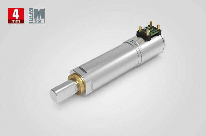
Size Boundary — What Counts as “Micro”?
In practice, “micro” or “miniature” refers to an outside diameter of roughly 4 mm to 30 mm. Below about 10 mm (for example maxon’s 6 mm planetary heads or 4.3 mm micro planetary units) the industry often speaks of “sub-miniature” or “micro” gearheads; 10–30 mm covers the bulk of medical, robotics, and consumer-actuator applications. The defining constraint is not torque alone but torque density—how much output torque fits in the allowable envelope and mass budget.
Gearhead vs. Gear Motor
A gearhead is the reduction stage only; it is specified by ratio, backlash, and rated torque and is mated to a chosen motor. A micro gear motor is the factory-aligned combination, where the motor shaft, pinion, and gearbox are pre-assembled to a defined concentricity (typically radial runout ≤0.1 mm). Buying the integrated unit removes assembly error and is the norm for OEM production runs where consistency matters more than field-serviceability.
How a Micro Gearbox Works
The operating principle is mechanical gear reduction. A small motor spins fast—often 3,000 to 30,000 rpm—but at low torque. The gear train steps that speed down, and torque scales up by (approximately) the ratio, minus friction losses.
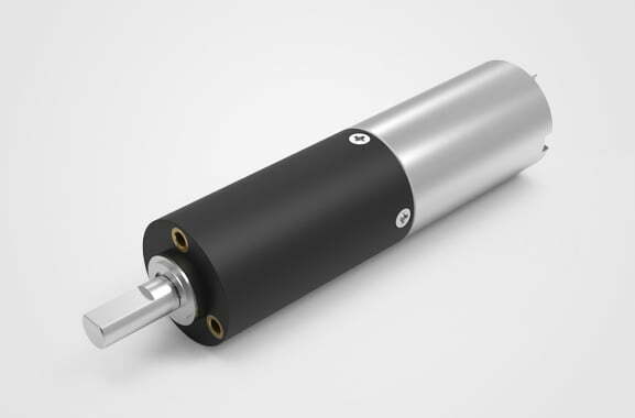
The Speed–Torque Trade
For an ideal lossless reducer, output torque = input torque × ratio. Real units lose 8–60% of that potential to gear mesh friction, bearing drag, and lubricant churn. The output shaft therefore turns slower and harder, which is exactly what a load such as a gripper, valve, or lead screw requires.
Core Equations
- Reduction ratio:
i = n₀ / nₙ(input speed ÷ output speed) - Output torque (ideal):
Tₙ = T₀ × i - Output torque (real):
Tₙ = T₀ × i × ηₙwhere ηₙ is gearbox efficiency - Output speed:
nₙ = n₀ / i - Output power:
Pₙ = (Tₙ × nₙ) / 9.55(T in N·m, n in rpm, P in W) - Motor input torque needed:
T₀ = Tₙ / (i × ηₙ)
Balancing the motor: the motor’s rated torque T₀ and speed n₀ fix the maximum achievable output. Picking a ratio that demands more than the motor can deliver at the available current simply stalls the system. See the torque calculation guide for motor-side math.
Backlash Accumulation and Encoder Placement
Each gear stage contributes its own tooth clearance, so total backlash grows with stage count—a 3-stage planetary can show roughly 1.5× the single-stage figure. Where positioning repeatability matters, mount the encoder on the output shaft rather than the motor side, so gearbox lost motion is measured directly at the load. For closed-loop drive of the motor itself, see the motor controller guide.
Micro Gearbox Types Compared
Five gear architectures dominate the miniature segment. Each trades efficiency, backlash, envelope, and cost differently.
| Type | Ratio Range | Efficiency | Backlash | Self-Lock | Torque Density | Typical Ø | Best For |
|---|---|---|---|---|---|---|---|
| Spur (inline) | 5:1–150:1 | 85–95% | 1–4° | No | Low | 6–30 mm | Toys, dispensers, simple pumps |
| Planetary | 4:1–360:1 | 70–90% | 0.5–2° | No | High | 4–30 mm | Medical, robotics, smart locks |
| Worm | 10:1–60:1 | 30–70% | 2–6° | Yes* | Medium | 10–30 mm | Valves, beds, hold-position |
| Harmonic | 30:1–320:1 | 70–90% | <1° | No | Very high | 15–30 mm | Robot joints, optics |
| Bevel | 1:1–5:1 | 90–95% | 1–3° | No | Low | 10–30 mm | Right-angle corner turns |
*Worm drives self-lock only at typical lead angles; do not rely on manual back-driving.
Spur (Inline)
Straight or helical gears on parallel shafts. Cheapest and simplest, with the highest single-stage efficiency, but only moderate torque density and the noisiest option at 50–60 dB at 0.5 m. Suitable for light-duty indexing and low-cost actuators.
Planetary (Epicyclic)
A sun gear drives planet gears carried in a carrier against an internal ring gear. Load is shared across multiple teeth, delivering the highest torque density in a coaxial package. This is the workhorse for precision planetary applications in surgical tools, grippers, and locks. Single-stage efficiency runs 88–92%; see the full reducer type comparison for the broader size range.
Worm (Right-Angle, Self-Locking)
A worm screw meshes with a wheel to give large single-stage ratios and a right-angle output. The friction that creates self-locking also wastes 30–60% of input power as heat—fine for intermittent holding, poor for continuous battery duty. Compared in detail in our worm gearbox guide; for higher-ratio alternatives see the cycloidal reducer guide.
Harmonic (Strain Wave)
A flexible spline elastically deforms against a rigid spline for very high ratios in a short length and near-zero backlash. Expensive and limited in shock load, but unmatched for robot joints and optical positioning. Weigh the trade against planetary in the harmonic vs. planetary comparison.
Bevel (Right-Angle, Coplanar)
Conical gears intersecting at 90° (or another angle) for corner-turn power transmission. High efficiency but low ratio per stage; often combined with other types. Relevant where a motor must drive a perpendicular shaft in tight space.
Engineering Data: Efficiency, Temperature, and Torque
Efficiency by Type and Stage Count
| Type | 1-Stage η | 2-Stage η | 3-Stage η |
|---|---|---|---|
| Spur | 90–95% | 85–92% | 80–88% |
| Planetary | 88–92% | 82–88% | 74–84% |
| Worm | 40–70% | — | — |
| Harmonic | 70–90% | — | — |
| Bevel | 90–95% | — | — |
Every added stage multiplies friction, so a 3-stage planetary at ~78% wastes more than a 2-stage at ~85%. Stage count is a direct efficiency and length penalty—keep it minimal.
Temperature and Lubricant Limits
| Lubricant / Material | Continuous Range | Notes |
|---|---|---|
| Sintered-oil bearing + grease | −20 °C to +85 °C | Standard metal micro box |
| Engineering plastic gears | −10 °C to +60 °C | Cost-sensitive consumer |
| PFPE (medical grade) | −40 °C to +200 °C | Biocompatible, autoclave-capable |
| Lithium-moly / solid grease | −30 °C to +120 °C | Industrial, re-lube ~2000 h |
Under continuous S1 duty, gearbox temperature rise is proportional to power loss. Running a 25 mm planetary at 100% load for 2 hours can soften standard grease; size for the thermal ceiling, not just the torque rating. Motor winding insulation class follows IEC 60034-1 (also summarized in our motor efficiency class guide), typically Class B (130 °C) or F (155 °C); flange and shaft dimensions follow our motor flange reference.
Backlash and Torque Density
Backlash (lost motion on reversal) is the single biggest precision parameter. Medical and optical stages often require <1° (planetary 2-stage ≤2°, harmonic <1°). Torque density—output torque per unit mass—favors planetary and harmonic. A 16 mm planetary can deliver 0.3–1.2 N·m continuously; the same envelope in spur would need a much larger diameter. Accuracy classes for the cut gears reference AGMA 2001-D04 and ISO 1328.
Best Applications for Micro Gearboxes
Medical and Surgical Devices
Infusion pumps, surgical drivers, and endoscopic articulators demand low noise, biocompatible lubricants, and tight backlash. A 6–16 mm planetary or harmonic head with PFPE grease is typical; autoclave-rated units survive sterilization cycles exceeding 10,000 operations.
Robotics and Automation
Gripper fingers, wrist joints, and linear actuators use planetary heads for coaxial torque in minimal length. The planetary gear-motor application field covers grippers, rotary joints, and wheeled platforms. Cobot wrists frequently pair harmonic and planetary stages.
Optics, Consumer, and Automotive
Camera gimbals, microscope focus, smart locks, electric curtains, and automotive actuators prioritize quiet running and consistent mass-production quality. Spur or low-ratio planetary keeps cost down; flat BLDC gear motors suit low-profile builds.
How to Select a Micro Gearbox
Selection Checklist
- Define output: required torque
Tₙand speednₙ. UsePₙ = (Tₙ × nₙ) / 9.55. - Match motor: compute
T₀ = Tₙ / (i × ηₙ)and confirm the motor supplies it at rated current. - Pick ratio:
i = n₀ / nₙ, then verify torque headroom (aim 1.5× load). - Set duty & thermal: continuous S1 needs thermal headroom; intermittent S2/S3 is more forgiving.
- Check envelopes: outside diameter, overall length, output shaft bore, and mounting.
- Verify loads: radial and axial limits on the output shaft—exceeding them wears the bearing.
- Noise & backlash: set measurable dB and arcmin targets, not vague “quiet / precise.”
- Request L10 life: compare suppliers by documented life, not marketing claims.
For the general methodology across all reducer sizes, see the speed-reducer motor selection guide.
Duty classification matters as much as ratio. IEC 60034-1 defines S1 (continuous), S2 (short-time), and S3 (intermittent) cycles; a micro gear motor rated for S1 can run indefinitely, while an S2/S3 unit overheats if forced into continuous service. Apply a service factor of 1.5–2× on torque for shock loads and belt or lead-screw tension. Compare the gear-motor approach with direct-drive vs. gear-motor trade-offs when the envelope allows.
Worked Example — Robotic Finger Joint
Requirement: a robotic gripper finger needs Tₙ = 0.5 N·m continuous at nₙ = 120 rpm, running on a 24 V supply with S1 duty. The chosen motor is a 16 mm BLDC rated T₀ = 0.020 N·m at n₀ = 6000 rpm (motor efficiency 85%). A 2-stage planetary gearbox is proposed (ηₙ ≈ 85%).
| Step | Calculation | Result |
|---|---|---|
| Ratio for speed | i = 6000 / 120 | 50:1 |
| Output torque at 50:1 | 0.020 × 50 × 0.85 | 0.85 N·m |
| Torque headroom | 0.85 / 0.5 | 1.7× (good) |
| Output power | (0.85 × 120) / 9.55 | 10.7 W |
| Motor input power | 10.7 / (0.85 × 0.85) | 14.8 W |
| Supply current @24 V | 14.8 / 24 | 0.62 A |
A 50:1 planetary meets speed exactly and gives 1.7× torque headroom for a long, cool life. Backlash of a 2-stage planetary (≤2°) is acceptable for finger positioning.
Common Engineering Mistakes
- Over-ratioing. Selecting the maximum catalog ratio raises friction, length, and backlash, and can prevent motor start.
- Ignoring shaft load limits. Belt tension or lead-screw thrust bends the output shaft and rapidly wears the bearing.
- Confusing continuous vs. peak torque. Peak torque is allowed only briefly; S1 duty must use the continuous rating.
- Choosing worm for battery devices. Self-lock seduces, but 30–70% efficiency destroys runtime.
- Forgetting lubricant thermal limits. Continuous duty softens grease and seizes the box.
- No stall-current protection. A stalled motor draws 5–10× rated current, burning windings or stripping teeth.
- Vague specs. “Low noise” and “high precision” mean nothing without dB and arcmin targets.
- Skipping L10 data. Comparing suppliers by claims instead of documented life hours.
Troubleshooting Micro Gearboxes
| Problem | Likely Cause | Solution |
|---|---|---|
| Excessive noise | Gear eccentricity; spur in noise-sensitive app; dry lube | Use planetary/helical; re-lube; check runout ≤0.1 mm |
| Premature wear | Misalignment >0.05 mm; overload; contamination | Re-align motor shaft; size to 1.5× load; seal for dust |
| Overheating | Worm in continuous duty; over-ratio; stall | Switch to planetary; add current limit; derate |
| Backlash growth | Bearing play; wear; no preload | Specify preloaded planetary; reduce radial load |
| Seized / no rotation | Stall burned windings; grease solidified | Current-limiting circuit; periodic exercise; warmer lube |
| EMI / erratic control | Brushed commutation noise | 0.1 µF cap across terminals + to case; shielding |
FAQ
What diameter counts as a “micro” gearbox?
Typically 4 mm to 30 mm outside diameter. Below ~10 mm the industry often calls the unit sub-miniature or micro gearhead; 10–30 mm covers most medical, robotics, and consumer actuators.
Planetary or spur for a small device?
Planetary wins for torque density and low backlash in minimal length, at higher cost. Spur is cheapest and most efficient per stage but noisier and lower-density—fine for light-duty indexing.
Can a micro worm gearbox be back-driven?
Generally no—worm drives are self-locking at typical lead angles, which is why they hold position without power. Do not rely on manual back-driving; forcing it can strip the wheel teeth.
How is backlash specified and why does it matter?
Backlash is the angular lost motion (in degrees or arc-minutes) when the output reverses direction under no load. It directly sets positioning repeatability in valves, optics, and encoder loops—medical stages often need <1°.
Brushless or brushed motor for a micro gear motor?
Brushless (BLDC) lasts 10,000+ hours with low EMI and is preferred for medical and continuous duty; brushed is lowest-cost and simplest but wears out (1,000–3,000 h) and needs EMI suppression. See servo and BLDC background.
How long do micro gearboxes last?
Suppliers rate them by L10 life—the hours until 10% of a sample fails under a specified load and speed. Proper sizing and staying within thermal and load limits yield thousands to 10,000+ hours; over-ratioing or exceeding shaft loads shortens life sharply.
Why Choose Greensky Power?
Greensky Power is a China-based custom electric motor and micro gearbox manufacturer serving medical, robotics, automotive, and consumer OEMs worldwide. Our micro gear motors integrate brushed DC, 24V BLDC, stepper, and coreless motors with spur, planetary, and worm gearheads in diameters from 4.3 mm upward. We support OEM/ODM customization—ratio, shaft, flange, encoder, and brake—with documented torque, backlash, and L10 data rather than generic claims. For application sizing, our engineers work from your output torque, speed, and duty-cycle requirements to specify the smallest ratio that meets the target with headroom.
Related Resources
- Gearbox overview (pillar page)
- Different types of speed reducers
- Precision planetary gearbox deep dive
- Worm gearbox selection guide
- Cycloidal reducer explained
- Harmonic drive vs. planetary gear
- Direct-drive vs. gear-motor trade-offs
- Speed-reducer motor selection guide
- What is the use of a DC geared motor?
- BLDC flat gear motor
- How to select a motor for an industrial application
- Electric motor basics
- Brushless DC motor (BLDC) basics
- Motor efficiency classes
- Motor flange dimensions
- DC motors category
References
- IEC 60034-1:2022 — Rotating electrical machines, general requirements (motor insulation & temperature classes). webstore.iec.ch/en/publication/65446
- IEC 60034-30-1 — Efficiency classes of line-operated AC motors. webstore.iec.ch/publication/91195
- ANSI/NEMA MG 1-2021 — Motors and Generators standard. webstore.ansi.org/standards/nema/ansinemamg2021
- NEMA — Motor and Generator product resources. nema.org/products/pages/motor-and-generator.aspx
- U.S. DOE — Motor load and efficiency reference. energy.gov/sites/prod/files/2014/04/f15/10097517.pdf
- IEA — Electric motors and energy efficiency. iea.org/energy-system/industry/electric-motors
- SKF — Bearing failures and their causes. skf.com/group/support/bearing-failures-and-their-causes
- Siemens — SIMOTICS electric motors. siemens.com/global/en/products/drives/electric-motors.html
- IEEE Xplore — Peer-reviewed micro motor / gear train design paper. ieeexplore.ieee.org/document/6342334
- maxon — EC motor and gearhead technology. maxongroup.com/maxon/view/content/ec-technology
- FAULHABER — Brushless DC motor know-how. faulhaber.com/en/know-how
- Yaskawa — Motion and motor technical downloads. yaskawa.com/downloads/search-index
- AGMA — Gear rating and accuracy standards (AGMA 2001-D04). agma.org
- Tsubaki — Gear motor selection technical data (service factors). en.tt-net.tsubakimoto.co.jp/tecs/engd/gen/engd_gen_ggm_sry.asp
Technical content reviewed by Greensky Power applications engineering. Figures are typical industry ranges; final specification requires verification against the selected motor and duty cycle.
