
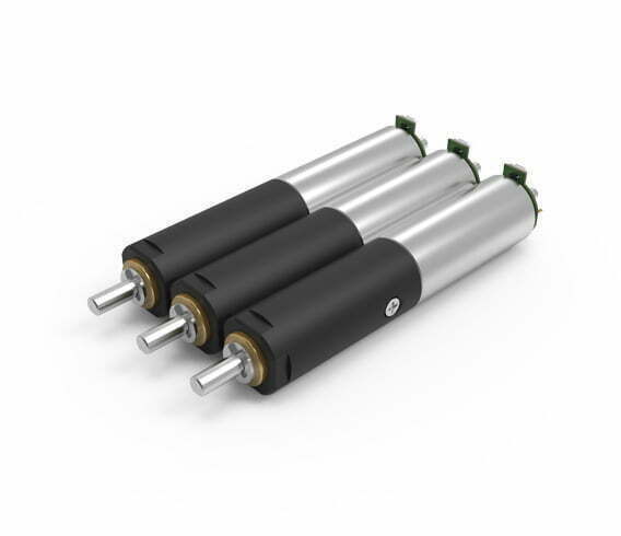
Precision Planetary Gearbox: Structure, Working Principle, Parameters & Applications
Quick Answer
A precision planetary gearbox is a coaxial speed reducer built around a central sun gear, three or more planet gears, a fixed internal ring gear, and a planet carrier that carries the output. The multiple simultaneous tooth meshes distribute load and cancel radial forces, which is why planetary units reach backlash of ≤1–5 arcmin, efficiency of 95–98% per stage, and high torsional stiffness in a compact can. You size one from the required reduction ratio, peak and RMS torque, the permissible backlash for your positioning tolerance, and the radial/axial load at the flange — not from the motor nameplate alone.
What Is a Precision Planetary Gearbox?
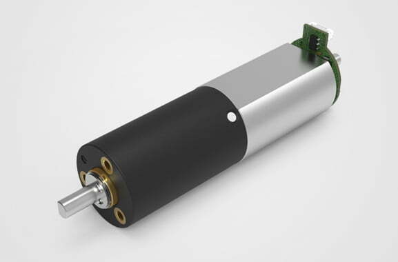
A planetary gearbox (also called a planetary reducer or epicyclic gearbox) is a speed-reduction device whose gears orbit like planets around a sun. A precision variant is simply one built and assembled to tighter tolerances: hardened-and-ground gears, preloaded bearings, and graded planet pin fits that remove the clearance a standard unit leaves in its tooth meshes. The result is low rotational play (backlash), high torsional rigidity, and repeatable positioning — the properties a servo or stepper axis needs to hit micron-level accuracy.
Precision planetary units sit in the same family as the other reducers covered in our different types of speed reducers guide, but they are the default choice whenever torque density and accuracy both matter in a tight envelope — robot joints, CNC rotary axes, AGV wheels, and medical automation. For continuous-duty high-efficiency drives where accuracy is secondary, a BLDC motor with a helical reducer is often the cheaper answer.
Precision Planetary Gearbox Structure Composition
Every precision planetary gearbox contains four functional elements, arranged on a common axis:
| Element | Role | Construction notes for precision grades |
|---|---|---|
| Sun gear | Input. Driven directly by the motor shaft at high speed. | Single-piece, hardened and ground; often integrally machined onto the motor shaft for zero coupling error. |
| Planet gears | Intermediate gears. Mesh simultaneously with the sun and the ring. | Typically 3 or 4 identical gears, balanced in mass to keep the carrier dynamically symmetric. |
| Ring gear (annulus) | Fixed outer gear with internal teeth. The planets “walk” inside it. | Case-hardened steel or nitrided; its tooth form sets the achievable backlash floor. |
| Planet carrier | Output. Holds the planet shafts and rotates at the reduced speed. | Precision-bored for equal planet spacing; integrated output flange or shaft per motor flange standard. |
Units are stacked by stage: a single stage gives a ratio of roughly 3:1 to 10:1; a second stage compounds it to ~100:1; a third reaches several hundred to one. More stages mean more torque and ratio range but lower overall efficiency and greater length. The trade-off is quantified in the parameters section below.
How Does a Precision Planetary Gearbox Work?
The motion is easiest to follow by holding one element fixed and driving another:
- Input. The motor spins the sun gear. In a precision servo unit this is usually a BLDC or brushed DC motor through a matched controller.
- Planet action. Each planet gear rolls on the sun (external mesh) while also rolling inside the fixed ring gear (internal mesh). Because the ring cannot rotate, the planets are forced to orbit the sun rather than spin in place.
- Output. The planet carrier — the arm that holds the planet shafts — rotates in the same direction as the sun but at the reduced speed. The carrier becomes the output shaft.
- Reaction path. Torque reacted at the ring gear is absorbed by the housing, so the input and output shafts see only axial, not radial, load. That coaxial load path is the reason planetary boxes stay rigid under high dynamic torque.
The mechanism is explained in more depth on our how a planetary gearbox works page, including the fixed-carrier, fixed-ring, and fixed-sun configurations that change which element is input, output, or reaction.
Reduction Ratio — The Core Formula
For the dominant configuration (sun input, carrier output, ring fixed), the ratio comes straight from tooth counts:
i = (Z_ring + Z_sun) / Z_sun
Example: a sun with 12 teeth and a ring with 72 teeth gives i = (72 + 12) / 12 = 7:1 in one stage. Two such stages in series give 7 × 7 = 49:1. Because three or four planets share the load, the per-tooth contact stress at this ratio is a fraction of what a single-mesh spur set would see — which is the physical origin of the high torque density.
Feature Comparison: Planetary vs Other Reducer Families
| Property | Planetary (precision) | Worm | Harmonic (strain wave) | Cycloidal |
|---|---|---|---|---|
| Backlash | ≤1–5 arcmin (preloaded ≤1) | 5–30 arcmin, grows with wear | Near zero (single cup) | Very low |
| Efficiency / stage | 95–98% | 60–85% (sliding) | 65–90% | 85–93% |
| Torque density | High | Low | Very high | Very high |
| Self-locking | No | Yes above ~20:1 | No | No |
| Cost at 100:1 | Moderate (2 stages) | Low | High | High |
| Best use | Robotics, CNC, AGV | Hoists, gates | Semiconductor, surgical | Mixers, crushers |
For a robot or AGV drivetrain the comparison is close between planetary and harmonic — see harmonic vs planetary and planetary vs worm for the decision logic. For micro-scale drives, our micro gearboxes note covers the 3.4–38 mm envelope.
Engineering Parameters That Define Precision
Four metrics decide whether a planetary box is “precision” or merely “a planetary box”:
| Parameter | Typical precision range | Why it matters |
|---|---|---|
| Backlash | ≤1 to 5 arcmin | Angular play on direction reversal; directly sets repeatability. A 5-arcmin box cannot meet a ±0.01° spec. |
| Torsional stiffness | 30–120 N·m / arcmin | Resists elastic twist under load; sets servo loop bandwidth and following error. |
| Transmission efficiency | 95–98% per stage | Multiplies across stages; sets heat load and motor size. |
| Peak torque | 2–3× rated | Safe envelope during acceleration and e-stop; limited by planet bearing and ring yield. |
Temperature and lubrication limits
Greensky precision planetary units are rated for continuous duty from −25°C to +90°C ambient at the flange, with lifetime grease good to an internal gear temperature of about 100°C. Above that, the base oil bleeds from the thickener and the gear film fails — the same failure mode described for boiler auxiliary gear motors under sustained overload. Bearing life, not gear strength, is usually the limiting factor; SKF bearing guidance is the reference we use for L10h calculation.
Key formulas
Output speed: n_out = n_motor / i
Output torque (ideal): T_out = T_in × i × η
Overall efficiency (stages): η_total = η^N (N = number of stages)
Reflected load inertia: J_ref = J_load / i²
Torque from motor power uses the standard relation covered in how to calculate motor torque: T(N·m) = 9550 × P(kW) / n(rpm).
Best Applications for Precision Planetary Gearboxes
The box earns its cost premium wherever accuracy, rigidity, and torque density collide:
| Application | Why planetary | Typical ratio |
|---|---|---|
| Robotic joints & CNC rotary axes | Low backlash + high stiffness set path accuracy | 16:1–100:1 |
| AGV / AMR drive wheels | Coaxial package, torque density | 15:1–50:1 |
| Semiconductor & lab automation | Repeatable micro-positioning | 30:1–100:1 |
| Medical & imaging | Quiet, low-vibration, compact | 20:1–80:1 |
| EV & e-mobility actuators | See EV BLDC actuators; flat form factor | 10:1–40:1 |
| Packaging & textile machinery | High cycle rate, low maintenance | 10:1–30:1 |
Our planetary gear motor application fields and precision planetary applications pages carry more case detail. Where the load is a continuous pump or fan, a helical unit sized by motor efficiency class is the lower-cost route.
Step-by-Step Selection Process (with a Worked Example)
Follow the same chain we use for OEM quotations. Full method is in how to select a speed reducer motor.
- Define the motion. Load inertia, required output speed, duty cycle, and the positioning tolerance.
- Pick the ratio. i = n_motor / n_out. Round to a catalogue stage combination.
- Compute torque. T_out = T_in × i × η; apply a service factor of 1.25–1.5 for steady load, 2.0+ for reversing or shock.
- Check backlash & stiffness.
- Verify mechanical limits. Radial/axial load at flange distance, shaft and keyway — see what a motor flange is.
Worked example — robot elbow joint
Given: a 3000 rpm servo rated at 1.35 N·m must deliver 120 N·m at 30 rpm to an elbow joint requiring ±0.02° repeatability.
- Ratio: i = 3000 / 30 = 100:1. A single planetary stage maxes at ~10:1, so use two stages (e.g. 10 × 10).
- Torque: η per stage ≈ 0.97, two-stage η ≈ 0.94. T_out = 1.35 × 100 × 0.94 = 126.9 N·m ≥ 120 N·m. Passes.
- Backlash: ±0.02° = 1.2 arcmin, so specify a high-precision grade (≤1 arcmin, preloaded). A standard 3-arcmin box would miss the spec.
- Stiffness: servo bandwidth needs ≥ 40 N·m/arcmin — select a frame-sized unit in that band.
- Inertia check: J_ref = J_load / i²; with a reflected load well under the motor rotor inertia the motor is inertia-comfortable, avoiding the overspeed/overshoot that a poorly matched box would cause.
Counter-intuitive insight. At 100:1 the gearbox, not the motor, sets your cooling budget. A two-stage planetary at η≈0.94 wastes ~6% — about 75 W on a 1.2 kW axis. A single-stage worm at 100:1 runs near η≈0.50 and dumps ~600 W as heat, demanding a fan and oil cooler. Same motion, eight times the thermal load. Choosing planetary over worm here is a thermal and reliability decision, not just a price one — the same lesson appears in our mixer gear motor and AGV overheating case notes.
Common Engineering Mistakes
- Sizing to running torque only. Peak acceleration and e-stop torque routinely hit 2–3× running; ignore them and the planet bearings brinell.
- Buying on ratio, not backlash. A cheap 5-arcmin box looks fine on paper but writes positioning error straight into the part.
- Forgetting inertia matching. A huge ratio makes J_ref tiny, so the motor sees almost no load inertia — great for positioning, but it also means a small disturbance current causes large acceleration; tune the loop accordingly.
- Overlooking overhung load. A sprocket or pulley on the output shaft adds radial load the gearbox rating may not cover; verify against the flange load chart.
- Assuming planetary self-locks. It does not. Hold a vertical load with a brake or a worm stage, not wishful thinking.
- Mixing brands across motor, gearbox, drive. Tolerances and feedback scaling drift; a matched custom motor + reducer avoids the three-supplier mismatch.
Problem → Cause → Solution (Troubleshooting)
| Problem | Cause | Solution |
|---|---|---|
| Excess backlash / lost repeatability | Gear wear, lost preload, wrong grade | Specify preloaded high-precision grade; re-preload or replace carrier |
| Overheating at the flange | Overload, low-efficiency ratio, poor lube | Resize to higher-efficiency type, improve grease, add forced cooling; see AGV overheating cases |
| Noise / whine | Misalignment, contamination, tooth error | Re-align coupling, clean and regrease, check planet pin fit |
| Premature bearing failure | Radial overload, contamination | Check radial load spec, improve sealing, use larger frame |
| Reduced torque at speed | Internal wear, slip, wrong ratio | Inspect torque-loss causes, correct ratio |
| Output drift under load | Low torsional stiffness for the axis | Move to a stiffer (often larger) frame or higher-grade unit |
Why Choose Greensky for Precision Planetary Gearboxes
Greensky Power (not “Green Sky New Energy”) designs and builds micro to mid-frame precision planetary reducers and the DC planetary gear motors that pair them with our own BLDC and brushed prime movers and controllers. Because the motor, gearbox, and drive come from one supplier, feedback scaling and mechanical tolerances are matched rather than negotiated across three vendors.
- Frame range from 22 mm to 120 mm, 12 V to 72 V DC, ratios 3:1 to 1000:1 across single to three stages.
- Grade options from standard (≤5 arcmin) to high-precision preloaded (≤1 arcmin) for servo and CNC use.
- Custom interfaces — shafts, keyways, flanges, connectors — through our custom electric motor and OEM/ODM programmes.
- Flat and right-angle variants, including flat BLDC gear motors for axially constrained actuators.
Related Resources
- Gearbox overview and type index
- Different types of speed reducers
- How a planetary gearbox works
- Spur vs planetary gear motor
- Cycloidal reducer — deep dive
- How to select a motor for industrial use
References and Standards
- ISO 1328-1 — Cylindrical gears, accuracy (tooth form grades for precision boxes): https://www.iso.org/standard/63656.html
- AGMA 2001-D04 / AGMA 2015 — Fundamental rating of gear teeth: https://www.agma.org/
- IEC 60034-30-1 — Efficiency classes for low-voltage motors (gear-motor integration): https://webstore.iec.ch/publication/91195
- IEC 60034-1:2022 — Rotating electrical machines, general requirements: https://webstore.iec.ch/en/publication/65446
- ANSI/NEMA MG 1 — Motors and Generators (motor + gear-motor ratings): https://webstore.ansi.org/standards/nema/ansinemamg2021
- US DOE — Motor and drive efficiency guidance: https://www.energy.gov/sites/prod/files/2014/04/f15/10097517.pdf
- IEA — Electric motors system efficiency: https://www.iea.org/energy-system/industry/electric-motors
- SKF — Bearing failures and their causes: https://www.skf.com/group/support/bearing-failures-and-their-causes
- Siemens — SIMOTICS gear motors: https://www.siemens.com/global/en/products/drives/electric-motors.html
- maxon — Gear technology white paper (“short and to the point”): https://www.maxongroup.com/assets/public/caas/v1/media/98114/data/32bb5bfabd9ce7d852292f275410c997/knowledge-support-support-antriebswissen-kurz-erklaert-gear-download.pdf
- FAULHABER — Drive system know-how: https://www.faulhaber.com/en/know-how/
- Yaskawa — Motion and servo drive technical library: https://www.yaskawa.com/downloads/search-index
- IEEE Xplore — Epicyclic gear train design paper: https://ieeexplore.ieee.org/document/6342334
Technical review statement: this article was prepared by the Greensky Power engineering team and reviewed against ISO 1328, AGMA 2001, IEC 60034, and NEMA MG 1. Figures are typical catalogue values; confirm exact ratings against the datasheet for your frame and grade before specification.
FAQ
What is a precision planetary gearbox?
It is a coaxial epicyclic reducer — sun, planets, ring, carrier — built and preloaded to tight tolerances so backlash stays at or below a few arcminutes, giving repeatable, accurate motion for servo and stepper axes.
How does a planetary gearbox achieve low backlash?
By using oversized planet gears selected for slight interference and preloaded precision bearings. The gear teeth are held in contact on both flanks, removing the clearance a standard mesh leaves. Hardened-and-ground tooth forms (per ISO 1328 accuracy grades) keep that contact stable under load.
What is the efficiency of a planetary gearbox?
About 95–98% per stage. Two stages typically land near 90–94% overall, three stages near 86–90%. That is far above a worm unit, where a 100:1 single stage can sit near 50%.
How do you calculate the reduction ratio?
For a fixed ring gear, i = (Z_ring + Z_sun) / Z_sun. A 12-tooth sun and 72-tooth ring give 7:1 in one stage; stacking stages multiplies the ratio.
Planetary or harmonic drive for a robot joint?
Planetary wins on cost, shock load, and stiffness for most industrial joints; harmonic wins on near-zero backlash in a tiny package for semiconductor and surgical robots. The detailed trade is in our harmonic vs planetary comparison.
How do you size a planetary gearbox for a servo axis?
Start from the motion profile: required output speed sets the ratio, peak torque (with a service factor) sets the frame, and the positioning tolerance sets the backlash grade. The worked robot-joint example above shows the arithmetic end to end.
What causes planetary gearbox noise and how do you reduce it?
Usually misalignment, contamination, or an out-of-grade tooth error. Re-align the coupling, clean and regrease, and confirm the planet pin fit; if noise appears only under load, the unit is likely under-sized on stiffness.
