
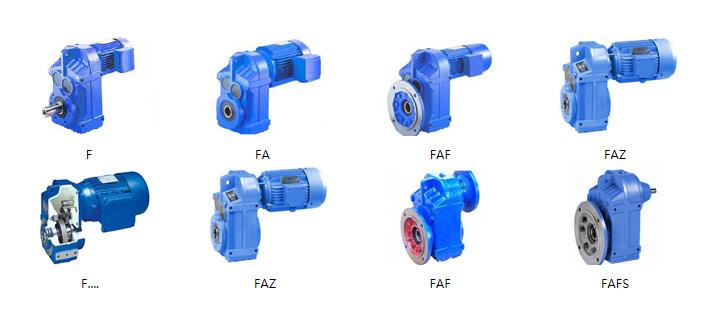
Different Types of Speed Reducers
Quick Answer
What Is a Speed Reducer?
A speed reducer is a power-transmission assembly that connects an electric motor (or engine) to a load and changes the speed-torque point at which power is delivered. It does one job with mathematical precision: it divides rotational speed by the gear ratio i and multiplies torque by i × η, where η is the transmission efficiency. The device is called a gearbox when you emphasize the hardware and a “speed reducer” when you emphasize the function — they are the same machine. A gear motor simply presses the reducer and motor into one matched housing.
The physics is fixed: power is conserved minus losses. If a 1,500 rpm motor rated at 2 N·m is fitted with a 10:1 reducer at 95% efficiency, the output is 150 rpm and roughly 19 N·m. That trade — less speed, more force — is exactly why reducers sit between almost every motor and every load that moves slowly under weight.
How a Speed Reducer Works — Step by Step
- Input from the motor. The motor shaft (or pinion) delivers high-speed, low-torque rotation. For a brushless unit this comes from a BLDC motor; for lower-cost designs, a brushed DC motor.
- Gear meshing. The input pinion drives a larger gear. Because the output gear has more teeth, it completes fewer revolutions per input revolution — speed is divided by the tooth ratio.
- Torque multiplication. Conservation of energy forces torque up by the same ratio, reduced only by mesh friction.
T_out = T_in × i × η. - Load sharing (planetary/cycloidal). Multiple planet or cycloidal pins share the load simultaneously, which is why these types punch far above their size in torque density.
- Output to the load. The reduced-speed, multiplied-torque shaft drives the conveyor, actuator, or wheel through a flange or shaft per standard motor flange dimensions.
Types of Speed Reducers — Feature Comparison
The table below summarizes the five families buyers actually specify, with the engineering numbers that drive selection. Detailed mechanism write-ups live on our gearbox overview and individual type pages.
| Type | Typical ratio (single stage) | Efficiency | Backlash | Shaft geometry | Self-locking |
|---|---|---|---|---|---|
| Spur | 1:1 – 10:1 (multi-stage to 200:1) | 96–98% | Moderate (5–20 arcmin) | Inline | No |
| Helical | 1:1 – 10:1 (multi-stage to 200:1) | 95–98% | Low–moderate (<10 arcmin precision) | Inline or parallel | No |
| Planetary | 3:1 – 10:1 (to 1000:1 multi) | 95–97% | Very low (1–16 arcmin, <3 precision) | Coaxial | No |
| Worm | 5:1 – 100:1 | 50–90% (falls with ratio) | Poor–moderate (adjustable) | Right-angle | Yes (ratio > ~20–25:1) |
| Cycloidal | 6:1 – 87:1 (to 7569:1 multi) | 85–93% | Low (1–5 arcmin) | Coaxial / right-angle | No |
| Harmonic | 30:1 – 320:1 | 60–90% | Ultra-low (<1 arcmin) | Coaxial | No |
| Bevel | 1:1 – 6:1 per stage | 95–98% | Low–moderate | Right-angle | No |
Two pairings deserve their own comparison pages because buyers argue about them constantly: spur vs planetary and planetary vs worm. For micro-scale drives, see what micro gearboxes are.
Spur and Helical Reducers
Spur gears are the simplest: straight teeth, cheapest to cut, fine for constant loads. Helical gears angle the teeth so engagement is gradual, cutting noise and vibration — which is why helical dominates appliance and general industrial duty. Both are the efficiency kings at 95–98% per stage.
Planetary Reducers
A sun gear drives three or more planet gears inside a ring gear. The planets share load, giving extraordinary torque density in a coaxial can. The mechanics are explained in how a planetary gearbox works. This is the default for robotic and AGV drivetrains.
Worm Reducers
A screw-like worm meshes a bronze wheel. You get a huge ratio in one right-angle stage and, above ~20–25:1, self-locking. The cost is efficiency — sliding friction can dump half the input power as heat at 100:1. Our NMRV worm gearbox line covers the common catalog ratios; deeper background is on the worm gear reducer page.
Cycloidal and Harmonic Reducers
Cycloidal drives use an eccentric cam and ring of pins for very high shock-load tolerance — ideal for mixers and crushers. Harmonic (strain-wave) drives flex a thin cup for near-zero backlash in a tiny package, used in semiconductor and surgical robots. See cycloidal and harmonic vs planetary.
Engineering Data You Must Size Against
Torque, Ratio, and the Output Formula
Start from the load. Output torque requirement T_load (N·m) and target speed n_out (rpm) fix the ratio against the motor’s speed:
i = n_motor ÷ n_out and T_out = T_motor × i × η
To convert a motor’s nameplate power to torque, use T(N·m) = 9550 × P(kW) ÷ n(rpm). In imperial units, T(lb·in) = 63025 × HP ÷ n(rpm). Worked examples are in how to calculate motor torque.
Efficiency Drops as Ratio Climbs
Efficiency is multiplicative across stages. A two-stage 100:1 worm train at 70% per stage delivers only ~49% overall — the motor must be sized accordingly. This is the single biggest hidden cost in worm selections and the reason motor efficiency class matters upstream.
| Configuration | Typical overall efficiency |
|---|---|
| Helical, single stage 5:1 | 96–98% |
| Planetary, single stage 10:1 | 95–97% |
| Worm, 10:1 | 85–90% |
| Worm, 60:1 | 60–70% |
| Worm, 100:1 | 50–60% |
| Cycloidal, single stage 30:1 | 88–92% |
| Harmonic, 100:1 | 75–85% |
Temperature Limits — It’s About the Lubricant
A reducer has no winding, so its temperature ceiling is set by grease, seals, and bearings — not by an insulation class. Standard lithium-complex grease operates roughly −20 °C to +120 °C; synthetic extends to −40 °C to +160 °C. Nitrile (NBR) seals fail around +100 °C while FKM (Viton) holds to +200 °C. Bearing temperature limits follow SKF’s bearing failure guidance. Where a motor’s insulation class (per IEC 60034-1) is the limit on the electrical side, the reducer’s limit is purely mechanical.
Service Factor and Duty
Never size to the exact running torque. Apply a service factor (SF) of 1.25–1.5 for steady conveyor loads and 2.0–2.5 for reversing, shock, or hoisting duty. The full method is in how to select a motor for an industrial application.
Best Applications for Each Reducer Type
- Helical / Spur — conveyors, pumps, fans, compressors, mixers, packaging lines. The workhorses of HVAC and process cooling.
- Planetary — robotic joints, AGV drives, CNC axes, EV actuators, wind-turbine pitch, medical imaging. High torque density where space is tight.
- Worm — lifts, gates, inclined conveyors, steering, positioning where self-locking holds the load. Common in mixer and gate drives.
- Cycloidal — heavy shock loads: crushers, agitators, bucket elevators, steel and mining.
- Harmonic — semiconductor handling, aerospace, surgical robots, pan-tilt where backlash under 1 arcmin is mandatory.
- Bevel — right-angle transfers in agriculture, marine, and mining equipment.
For precision planetary use cases specifically, see precision planetary gearbox applications.
Step-by-Step Speed Reducer Selection
- Define the load. Lock down required output speed (rpm), continuous torque (N·m), and peak torque including acceleration.
- Compute the ratio.
i = n_motor ÷ n_out. Match the motor’s nameplate using torque calculation. - Pick the geometry. Inline/coaxial → planetary or helical. Right-angle → worm or bevel. Compare in direct drive vs gear motor.
- Apply the service factor. Multiply running torque by 1.25–2.5 for shock and duty. Skipping this is the most common RFQ error we see.
- Check efficiency and heat. A 100:1 worm at 55% means the motor burns nearly double the watts of a planetary at 96%. Size the motor and cooling for the loss.
- Set the backlash spec. Positioning axes need planetary (<3 arcmin) or harmonic (<1 arcmin); a conveyor does not care.
- Verify mechanical limits. Permitted radial/axial load at flange distance, shaft diameter, flange pattern, and total length. Background: what a motor flange is. Confirm environment: IP rating, lubricant, and controller compatibility.
Common Engineering Mistakes
- Sizing to running torque without a service factor. A conveyor that jams once a shift lives or dies on the SF you skipped.
- Assuming every worm reducer self-locks. Below ~20:1 or with a two-start worm and vibration, the load back-drives. Confirm with the supplier before omitting a brake.
- Ignoring thermal rating at low efficiency. A 100:1 worm turns input power into heat. Without forced cooling the grease cooks and the bronze wheel wipes out.
- Buying on price, ignoring backlash. A cheap high-backlash unit destroys positioning repeatability on a servo axis. Match precision class to the job.
- Mismatched input shaft or coupling. Wrong bore, keyway, or flange pattern means field machining or a returned unit. Verify the flange drawing before ordering.
- Wrong lubricant for temperature or orientation. Grease rated to +120 °C fails in a +160 °C washdown; oil in a vertical worm weeps past the seal. Specify the environment up front.
Troubleshooting: Problem → Cause → Solution
| Problem | Common cause | Solution |
|---|---|---|
| Overheating | Overload, low-efficiency ratio (worm), insufficient lubrication | Resize with higher-efficiency type, improve grease, add forced cooling; see AGV overheating cases |
| Excessive noise / vibration | Misalignment, worn gears, bearing defect | Realign shafts, inspect gears, replace bearings |
| Oil leakage | Seal failure, overfilled, blocked breather | Replace seal, correct oil level, clear vent |
| Premature bearing failure | Radial overload, contamination | Check radial load spec, improve sealing |
| Backlash growth | Gear wear, lost preload | Select precision class; replace worn stage |
| Worm back-drives (lift drops) | Ratio too low / vibration | Use higher ratio or add a brake; verify self-locking |
| Output shaft seized | Bearing seizure, contamination | Replace bearings, flush, re-lubricate |
| Corrosion in washdown | Wrong material / coating | Use stainless or coated housing, FKM seals |
| Reduced torque at speed | Internal wear, slip, wrong ratio | Inspect torque-loss causes, correct ratio |
Frequently Asked Questions
What is the difference between a speed reducer and a gearbox?
They are the same physical device. “Gearbox” describes the hardware; “speed reducer” describes its function of lowering input speed while multiplying torque. Both contain a gear set that trades rotational speed for torque.
Which speed reducer is the most efficient?
Spur and helical reducers reach 95–98% per stage. Planetary units run 95–97%. Worm reducers are the weakest: 50–90% depending on ratio, dropping toward 50% at 100:1 because sliding friction dominates.
Can a speed reducer increase speed?
A “reducer” by definition decreases speed and increases torque. Reversing the shaft connection (driving the output) creates a speed increaser, but that is a different configuration — do not assume a stock reducer is rated for it.
How do I calculate the reduction ratio?
Ratio i = input speed ÷ output speed = teeth on output gear ÷ teeth on input gear. A motor at 1,500 rpm driving a 150 rpm load needs i = 10. Output torque is then motor torque × i × efficiency.
Are worm gear reducers self-locking?
Often, but not always. Single-start worms typically self-lock above about 20–25:1 when the load cannot back-drive the worm. Below that, or with vibration and a two-start worm, back-driving is possible — verify with the supplier before relying on it for holding.
How long does a speed reducer last?
Life is set by the lubricant and bearings, not the gears. With correct service factor and proper lubrication, industrial reducers commonly exceed 20,000 operating hours. Contamination, overload, and wrong grease are the usual killers.
Why Choose Greensky for Speed Reducers?
Greensky Power is a China-based B2B manufacturer supplying gear motors and reducers to distributors and OEMs worldwide. For speed-reducer sourcing we offer:
- Full type coverage — helical, planetary, worm (NMRV), cycloidal, harmonic, and flat BLDC gear motors, sized to your load profile rather than a generic catalogue page.
- Custom ratios and mounting — frame sizes from 22 mm to 120 mm, 12 V to 72 V DC, with custom shafts, flanges, and connectors. See our custom electric motor development and OEM/ODM process.
- Application engineering — we run the torque, ratio, service-factor, and thermal checks above before quoting, so the unit arrives sized for the duty.
- Quality and testing — every reducer is checked for backlash, noise, and no-load current against its specification.
- Motor + reducer integration — matched BLDC or brushed prime movers with the right controller.
- Global B2B supply — MOQ flexibility, documentation, and logistics for distributors across North America, Europe, and Asia.
Related Resources
- Gearbox overview and type index
- Worm gear reducer — deep dive
- Cycloidal reducer — deep dive
- Harmonic vs planetary gear
- Spur vs planetary gear motor
- Planetary vs worm gear motor
- Different types of speed reducers
- How to select a motor for industrial use
References
- International Electrotechnical Commission. IEC 60034-1:2022, Rotating electrical machines — Part 1: Rating and performance. https://webstore.iec.ch/en/publication/65446
- International Electrotechnical Commission. IEC 60034-30-1:2025, Rotating electrical machines — Part 30-1: Efficiency classes of line operated AC motors (IE code). https://webstore.iec.ch/publication/91195
- National Electrical Manufacturers Association / ANSI. ANSI/NEMA MG 1-2021, Motors and Generators (official standard record). https://webstore.ansi.org/standards/nema/ansinemamg2021
- U.S. Department of Energy, Office of Energy Efficiency and Renewable Energy. Determining Electric Motor Load and Efficiency, DOE/GO-10097-517. https://www.energy.gov/sites/prod/files/2014/04/f15/10097517.pdf
- International Energy Agency. Electric Motors — Energy System / Industry. https://www.iea.org/energy-system/industry/electric-motors
- SKF Group. Bearing Failures and Their Causes. https://www.skf.com/group/support/bearing-failures-and-their-causes
- Siemens AG. SIMOTICS Electric Motors — Technical Documentation and Product Portfolio. https://www.siemens.com/global/en/products/drives/electric-motors.html
- Rasmussen, P. O. et al. Improved Motor Integrated Permanent Magnet Gear for Traction Applications. IEEE Energy Conversion Congress and Exposition. https://ieeexplore.ieee.org/document/6342334
- maxon group. Gear Technology — Short and to the Point: Gearhead Selection, Efficiency and Service Life. https://www.maxongroup.com/assets/public/caas/v1/media/112608/data/32bb5bfabd9ce7d852292f275410c997/knowledge-support-support-antriebswissen-kurz-erklaert-gear-download.pdf
- FAULHABER Drive Systems. Know-How: Technical Tutorials on Micro Drives and Gearheads. https://www.faulhaber.com/en/know-how/
- Yaskawa Electric Corporation. Technical Documents and Application Notes — Drives and Motion Control. https://www.yaskawa.com/downloads/search-index
- National Electrical Manufacturers Association. Motor & Generator Section — Standards and Efficiency Programs. https://www.nema.org/products/pages/motor-and-generator.aspx
This article was reviewed by the Greensky Power engineering team. Figures reflect common catalogue ratings; always confirm exact values against the specific model’s datasheet and applicable standards such as IEC 60034-1 and NEMA MG 1.
