
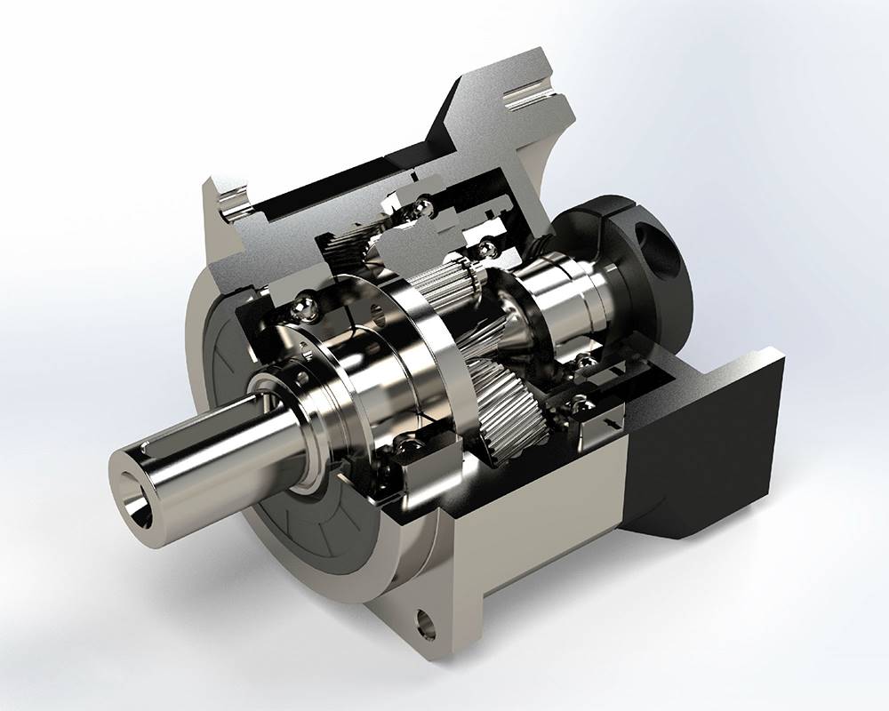
What Are the Advantages of a 3 Stage Planetary Gearbox?
Quick Answer
Contents
- What Is a 3-Stage Planetary Gearbox?
- How Stage Count Sets Ratio, Torque & Efficiency
- The Key Advantages of a 3-Stage Design
- The Trade-offs: Efficiency, Backlash & Length
- Engineering Data: Ratios, Efficiency, Backlash, Torque
- Stage Count Comparison: 1 vs 2 vs 3
- Best Applications for 3-Stage Planetary Gearboxes
- How to Select a 3-Stage Gearbox (Worked Example)
- Common Engineering Mistakes
- Troubleshooting
- FAQ
- Why Choose Greensky Power?
What Is a 3-Stage Planetary Gearbox?
A planetary gearbox is a coaxial speed reducer built from a sun gear, several planet gears carried on a common carrier, and an outer ring gear. One complete sun/planet/ring set is a single stage. A 3-stage unit places three such sets in series inside one housing, so the output of the first stage becomes the input to the second, and so on. The stage count is the single most important structural decision, because it is what determines the achievable reduction ratio before anything else.
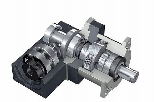
The classification is practical rather than rigid: a single-stage planetary gearbox typically covers 3:1 to 10:1, a two-stage unit extends to roughly 100:1 (sometimes 200:1), and a three-stage unit reaches 100:1 and beyond—up to 1,000:1 or more in precision series. This is the reason a third stage exists at all: single and two-stage reductions cannot reach those ratios without becoming impractically large. For the broader architecture and how each stage meshes, see how a planetary gearbox works and the speed-reducer type guide.
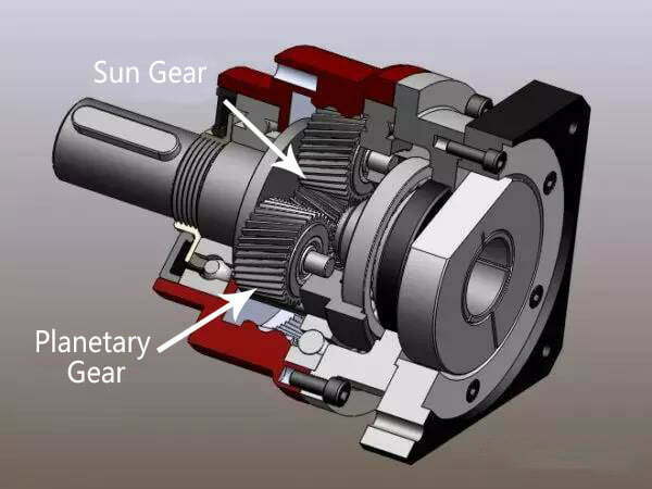
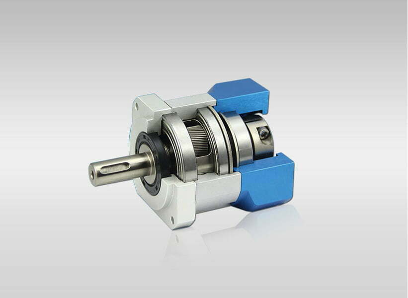
Internal structure diagram of single stage planetary gearbox
How Stage Count Sets Ratio, Torque & Efficiency
Every planetary stage multiplies the input by its own ratio, so stage ratios multiply. Two 10:1 stages give 100:1; three 10:1 stages give 1,000:1. The same multiplication applies to torque (minus friction) and—less obviously—to friction loss and backlash, which is where the trade-offs come from.
- Total ratio:
iₚ = i₁ × i₂ × i₃(product of stage ratios) - Output torque:
Tₙ = Tₔ × iₚ × ηₚ(ηₚ = overall efficiency) - Overall efficiency:
ηₚ = η₁ × η₂ × η₃(losses compound) - Reflected inertia:
Jₙ = Jₚ / iₚ²(inertia falls by the square of the total ratio)
Because efficiency compounds geometrically, a stage that is individually ~97% efficient yields only ~91% after three stages (0.97³ ≈ 0.913). The ratio and torque gains are linear-multiplicative, but the losses compound—this asymmetry is the heart of the 3-stage decision. The torque math and motor-side sizing are covered in our torque calculation guide.

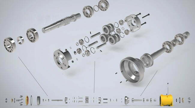
Internal structure diagram of two-stage planetary gearbox
The Key Advantages of a 3-Stage Design
- Very high reduction ratio in one unit. Three stages reach 100:1 to 1,000:1+ in a single coaxial housing—ratios a single or two-stage unit cannot deliver without an external gear pair.
- High output torque. Torque multiplies through every stage, so a compact three-stage box turns a small high-speed servo into a slow, high-torque drive.
- Compact coaxial package / high torque density. The inline sun-carrier-ring geometry keeps input and output on the same axis, so a 3-stage unit stays radially small (tens of millimetres to a few hundred) while delivering torque that would need a far larger parallel-shaft or worm reducer.
- Load sharing / power split. Each stage spreads load across multiple planet gears (often three to five), lowering per-tooth force and improving tooth life versus a single pinion carrying the full load.
- Smooth, low-noise operation. Continuous multi-tooth meshing with no axial thrust (unlike helical or bevel) yields smooth running, typically under ~65 dB in precision units.
- Very low reflected inertia. Because reflected inertia falls by the square of the ratio, a 600:1 box makes the load feel nearly weightless to the motor—ideal for start/stop servo axes.
- Wide ratio flexibility. Stage ratios are selected from a catalogue set (e.g., 3/4/5/7/10), so a 3-stage unit can be built to hit a precise total ratio with standard parts.

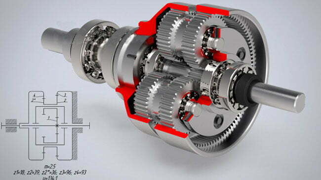
Internal structure diagram of 3 stage planetary gearbox
The Trade-offs: Efficiency, Backlash & Length
The advantages are real, but so are the costs. A 3-stage unit is not simply “better”—it is a different point on the ratio-versus-efficiency-versus-backlash curve.
Efficiency Drops Geometrically
Each stage loses ~2–3% to mesh friction and bearing drag, and those losses compound. In a 10 kW servo drive, a 3% per-stage loss is roughly 300 W of heat per stage dumped into the housing—heat that shortens lubricant life and affects long-term backlash stability under continuous duty. This is why three-stage units are usually reserved for high-ratio, lower-power or intermittent applications.
Backlash Accumulates, It Does Not Improve
This is the most common misconception—and a correction to the common claim that more stages improve “clearance accuracy.” In reality, each stage contributes its own tooth clearance, so total backlash grows with stage count: a single precision stage may hold ≤1 arcmin, a two-stage ≤3 arcmin, and a three-stage ≤14 arcmin (or 8–20 arcmin depending on grade). If positioning repeatability is the priority, a 3-stage box is the wrong tool—choose a single stage or a harmonic drive (near-zero backlash) instead.
Length and Weight Grow
Every added stage lengthens the housing and adds planet carriers and bearings. A three-stage box is noticeably longer than a two-stage unit of the same frame size, which can matter in a tight robot wrist or actuator envelope.
Engineering Data: Ratios, Efficiency, Backlash, Torque
Typical Stage-Count Specifications
| Configuration | Ratio range | Efficiency | Backlash (precision) | Best for |
|---|---|---|---|---|
| 1-stage | 3:1–10:1 | ≥97% | ≤1–8 arcmin | High-speed axes, robot joints |
| 2-stage | 10:1–100:1 | ≥94% | ≤3–12 arcmin | CNC tables, cobot joints, AGVs |
| 3-stage | 100:1–1,000:1+ | ≥91% | ≤14–20 arcmin | Heavy conveyors, slow precision actuators |
Efficiency Compounding Across Stages
| Stages | Formula (η = 0.97/stage) | Overall efficiency |
|---|---|---|
| 1 | 0.97¹ | 97% |
| 2 | 0.97² | 94.1% |
| 3 | 0.97³ | 91.3% |
| 4 | 0.97&sup4; | 88.5% |
Key Formulas for a 3-Stage Unit
| Quantity | Formula | Notes |
|---|---|---|
| Total ratio | i = i₁ × i₂ × i₃ | e.g., 10 × 10 × 6 = 600:1 |
| Output torque | Tₙ = Tₔ × i × η | η ≈ 0.91 for three stages |
| Motor torque needed | Tₔ = Tₙ / (i × η) | Size the servo to this |
| Reflected inertia | Jₙ = Jₚ / i² | 600:1 → inertia cut 360,000× |
| Output speed | nₙ = nₔ / i | 3,000 rpm → 5 rpm at 600:1 |
Stage Count Comparison: 1 vs 2 vs 3
| Feature | 1-stage | 2-stage | 3-stage |
|---|---|---|---|
| Ratio range | 3:1–10:1 | 10:1–100:1 | 100:1–1,000:1+ |
| Efficiency | ≥97% | ≥94% | ≥91% |
| Backlash | Lowest | Moderate | Highest (accumulates) |
| Axial length | Shortest | Medium | Longest |
| Reflected inertia | Highest | Low | Lowest |
| Relative torque density | High | Very high | Highest |
Best Applications for 3-Stage Planetary Gearboxes
| Application | Why a 3-stage fits | Typical ratio |
|---|---|---|
| Heavy-duty conveyors & material handling | High torque at low output speed | 100:1–300:1 |
| Slow-speed precision actuators | High ratio + coaxial packaging | 200:1–1,000:1 |
| Solar trackers & wind yaw drives | Very high ratio in one sealed unit | 300:1–1,000:1+ |
| Rotary tables & positioners | Torque density, predictable motion | 100:1–500:1 |
| Cranes & hoisting | Extreme torque in a compact radial size | 100:1+ |
For high-cycle servo axes where backlash matters more than ratio, compare the harmonic vs. planetary trade-off and the planetary gear-motor application field.
How to Select a 3-Stage Gearbox (Worked Example)
- Define the load. Output torque
Tₙ, output speednₙ, and duty cycle. - Compute the ratio.
i = nₔ / nₙfrom the motor’s rated speed. - Pick the stage count. If
i > 100:1, three stages (or two + external reduction). - Account for efficiency. Use
η ≈ 0.91and confirm the motor torque withTₔ = Tₙ / (i × η). - Check backlash budget. Confirm the 3-stage backlash (≤14 arcmin typical) meets your positioning spec; if not, reconsider the architecture.
- Verify thermal and life. Confirm the efficiency-driven heat load and the bearing life for the duty cycle.
Worked Example — Slow Rotary Actuator
Requirement: 60 N·m continuous at 5 rpm from a 3,000 rpm servo.
| Step | Calculation | Result |
|---|---|---|
| Required ratio | i = 3000 / 5 | 600:1 → needs 3 stages |
| Stage split | 10 × 10 × 6 | 600:1 total |
| Overall efficiency | 0.97³ | ≈ 91% |
| Motor torque | Tₔ = 60 / (600 × 0.91) | 0.11 N·m |
| Reflected inertia (0.2 kg·m² load) | Jₙ = 0.2 / 600² | 0.00000056 kg·m² (360,000× cut) |
| Backlash budget | 3-stage precision | ≤14 arcmin (verify vs. spec) |
A 600:1 three-stage planetary lets a tiny ~0.11 N·m servo deliver 60 N·m at 5 rpm in a coaxial package, and the reflected inertia is cut by 360,000×. The same ratio in a worm reducer would be far less efficient and bulkier; a two-stage planetary cannot reach 600:1 without an extra external gear pair.
Common Engineering Mistakes
- Choosing 3 stages for precision. Backlash accumulates with stages; use a single stage or harmonic drive for tight positioning.
- Ignoring efficiency compounding. Three ~97% stages yield ~91% overall—budget the heat, not just the torque.
- Over-ratioing. Piling on stages to maximize ratio adds length, backlash, and friction for no benefit.
- Assuming “more stages = better.” Each stage trades efficiency and length for ratio; more is not automatically better.
- Forgetting reflected inertia. The squared-ratio inertia cut is a benefit—but verify the motor-to-load inertia ratio for servo stability.
- Neglecting thermal limits. The added heat of a 3-stage unit shortens lubricant and bearing life under continuous duty.
- Missing output shaft load limits. Radial and axial loads on the output flange wear the carrier bearing regardless of stage count.
Troubleshooting
| Problem | Likely cause | Solution |
|---|---|---|
| Lower-than-expected output torque | Ignored efficiency compounding | Use η ≈ 0.91; re-check motor torque |
| Excessive backlash / lost position | 3 stages accumulated clearance | Spec single-stage or harmonic for precision |
| Overheating | Compounded losses under continuous duty | Reduce duty; add cooling; verify lubrication |
| Noise or vibration | Stage misalignment; dry lube | Re-align; re-lube; check planet carrier runout |
| Too long for the envelope | 3 stages add axial length | Reconsider 2-stage + external reduction |
| Motor stalls / won’t start | Reflected friction exceeds motor start torque | Verify ratio; add current limit; recheck inertia |
FAQ
What is the main advantage of a 3-stage planetary gearbox?
Very high reduction ratio (roughly 100:1 to 1,000:1+) and high output torque in a single compact coaxial housing—something a single or two-stage unit cannot reach without an external gear pair.
How is the total ratio of a 3-stage gearbox calculated?
The stage ratios multiply: i = i₁ × i₂ × i₃. Three 10:1 stages give 1,000:1; a 10 × 10 × 6 split gives 600:1.
Does a 3-stage gearbox have better backlash than a single stage?
No—the opposite. Backlash accumulates across stages, so a precision single stage may hold ≤1 arcmin while a three-stage unit is typically ≤14 arcmin. Choose a single stage or harmonic drive when positioning repeatability is the priority.
How efficient is a 3-stage planetary gearbox?
Roughly 91% overall, because stage efficiency compounds: three ~97%-efficient stages give 0.97³ ≈ 91.3%. Compare ~97% for a single stage and ~94% for two stages.
When should I choose 3 stages instead of 2?
When your required ratio exceeds roughly 100:1 and you want it in one coaxial package. Below ~100:1, a two-stage unit is shorter, more efficient, and has less backlash.
Why is reflected inertia so low in a 3-stage gearbox?
Reflected inertia falls by the square of the total ratio (J = J_load / i²). At 600:1 the load inertia is cut 360,000×, making the motor feel nearly unloaded and improving start/stop response.
Why Choose Greensky Power?
Greensky Power is a China-based manufacturer of gear reducers, custom motors, and integrated drives serving global OEMs since 2010. We build precision planetary gearboxes in single, two, and three-stage configurations, and we specify the ratio, efficiency, backlash, and duty cycle from your load data rather than shipping a catalogue default. Our engineering team sizes the stage count against your ratio requirement and positioning budget, and every unit is tested for torque, efficiency, noise, and temperature against IEC 60034 and NEMA MG 1 before shipment, with OEM/ODM customization of ratio, flange, and shaft. Start with the speed-reducer motor selection guide or browse the DC motors category.
Related Resources
- Gearbox overview (pillar page)
- How a planetary gearbox works
- Precision planetary gearbox deep dive
- Harmonic drive vs. planetary gear
- Precision planetary gearbox applications
- Different types of speed reducers
- Cycloidal reducer explained
- Worm gearbox selection guide
- Direct-drive vs. gear-motor
- 8 causes of helical gearbox wear
- How to reduce gear noise in a gear reducer
- Speed-reducer motor selection guide
- How to calculate motor torque
- Motor efficiency classes (IE)
- OEM / ODM customization
- DC motors category
References
- IEC 60034-1:2022 — Rotating electrical machines, general requirements (insulation & temperature classes). webstore.iec.ch/en/publication/65446
- IEC 60034-30-1 — Efficiency classes of line-operated AC motors (IE1–IE5). webstore.iec.ch/publication/91195
- ANSI/NEMA MG 1-2021 — Motors and Generators standard. webstore.ansi.org/standards/nema/ansinemamg2021
- NEMA — Motor and Generator product resources. nema.org/products/pages/motor-and-generator.aspx
- U.S. DOE — Motor load and efficiency reference. energy.gov/sites/prod/files/2014/04/f15/10097517.pdf
- IEA — Electric motors and energy efficiency. iea.org/energy-system/industry/electric-motors
- SKF — Bearing failures and their causes. skf.com/group/support/bearing-failures-and-their-causes
- Siemens — SIMOTICS electric motors. siemens.com/global/en/products/drives/electric-motors.html
- IEEE Xplore — Peer-reviewed electric machine design paper. ieeexplore.ieee.org/document/6342334
- maxon — EC motor and gearhead technology. maxongroup.com/maxon/view/content/ec-technology
- FAULHABER — Brushless DC motor know-how. faulhaber.com/en/know-how
- Yaskawa — Motion and motor technical downloads. yaskawa.com/downloads/search-index
- Tsubaki — Gear motor selection technical data (service factors). en.tt-net.tsubakimoto.co.jp/tecs/engd/gen/engd_gen_ggm_sry.asp
- AGMA — Gear rating and accuracy standards. agma.org
Technical content reviewed by Greensky Power applications engineering. Figures are typical industry ranges; final specification requires verification against the selected gearset and duty cycle.
