
8 Causes of Helical Gearbox Wear: Root-Cause Analysis and Prevention
Quick Answer
- What Is Helical Gearbox Wear?
- How Helical Gear Wear Develops
- The 8 Root Causes of Helical Gearbox Wear
- Helical vs. Spur Gear Wear Behavior
- Engineering Data: Stress, Hardness, Lubricant, Temperature
- Where Wear Matters Most
- How to Prevent Helical Gearbox Wear
- Common Engineering Mistakes
- Troubleshooting Table
- FAQ
- Why Choose Greensky Power?
- Related Resources
- References
What Is Helical Gearbox Wear?
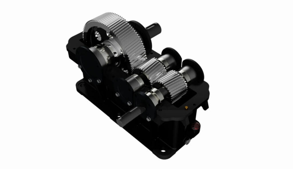
A helical gearbox is a speed reducer in which the teeth are cut at a helix angle (typically 15°–30°) so that load transfers gradually across multiple tooth pairs. That geometry gives helical units higher load capacity, lower noise, and better shock tolerance than spur-type reducers of the same size—but it also introduces sliding contact and an axial thrust component that spur gears do not have. “Wear” is the umbrella term for the material removed or damaged during operation, and it spans several distinct physical mechanisms.
Wear vs. Sudden Failure
Engineers often conflate wear with breakage. Wear is progressive and measurable (pitting, scoring, increased backlash, rising temperature); sudden failure is a single-event tooth break or shaft snap from overload. Both shorten life, but their root causes and fixes differ, so the first step in any audit is classification:
- Surface-driven wear — pitting, micro-pitting, scuffing, abrasive scoring. Root cause usually lives in the lubrication film, not the gear size.
- Volume-driven failure — tooth-root bending fatigue, shaft yield, bearing collapse. Root cause usually lives in load vs. rating (overload, misalignment, wrong service factor).
This distinction drives the whole article: most “helical gearbox wearing out” complaints are actually lubrication-film failures that a bigger gearbox would not fix. The speed-reducer selection guide covers rating fundamentals; the sections below go deeper into root cause.
How Helical Gear Wear Develops (Step by Step)
Helical tooth contact is a mix of rolling and sliding. The sliding component (absent in pure rolling) is what makes lubrication decisive. Wear progresses through four identifiable stages:
Stage 1 — Run-In and Micro-Geometry
New gears mate on the highest asperities first. A correct run-in (light load, clean EP oil) polishes these peaks and establishes a stable contact pattern. A poor run-in—full load from hour one, or dirty oil—imprints those peaks as permanent damage sites that later become pitting nuclei.
Stage 2 — Abrasive Wear (Contamination)
Hard particles (silica dust, metal fines, spent additive) embedded in the oil act like lapping compound, scratching the flank and raising surface roughness. Roughness destroys the oil film faster, accelerating every later stage. This is why enclosed drive hygiene matters as much as oil grade.
Stage 3 — Adhesive Wear and Scuffing
When the film breaks down locally (high spot pressure, wrong viscosity, overload), tooth surfaces momentarily weld and tear. The result is scuffing—smearing, transferred metal, and a matte grey streak along the tip/root. Scuffing is instantaneous and irreversible; it is the classic symptom of helical thrust or misalignment pushing local pressure past the EP additive’s capacity.
Stage 4 — Fatigue: Micro-Pitting and Macro-Pitting
Repeated contact stress below the surface initiates micro-cracks. Micro-pitting (grey, frosted appearance) roughens the flank within the first millions of cycles; left unchecked it grows into macro-pitting (visible craters) and finally spalling where a chunk of material ejects. The tooth root is the most critical initiation site because bending stress and shock load concentrate there. Condition monitoring via wear-debris analysis catches this early.
The 8 Root Causes of Helical Gearbox Wear
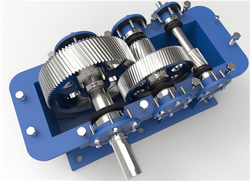
The original equipment note on this topic listed eleven loosely related bullet points (heat treatment, material, center distance, lubrication, and more). Field data from reliability studies clusters those into eight engineering root causes. The table summarizes them; each is detailed below.
| # | Root Cause | Primary Wear Mode | Key Indicator | First Fix |
|---|---|---|---|---|
| 1 | Inadequate or wrong lubrication | Scuffing, pitting | High tooth temperature, grey frosted flank | Use correct ISO VG + EP additive; verify oil level |
| 2 | Lubricant contamination | Abrasive scoring | 3-body wear lines, metal in sump | Seal breather, magnetic plug, oil analysis |
| 3 | Shaft misalignment / wrong center distance | Edge loading, bending loss | Wear at one flank edge, hot bearing | Re-align to ≤0.05 mm; check center distance |
| 4 | Overload and shock loading | Tooth-root bending, breakage | Broken teeth, high dB at load | Apply AGMA service factor 1.25–2.0 |
| 5 | Insufficient hardness / poor heat treatment | Plastic flow, rapid pitting | Soft flank, case <1 mm deep | Case-harden to spec; verify HRC |
| 6 | Material and metallurgical defects | Premature pitting, cracking | Porosity, inclusions, coarse grain | Specify certified material; metallography |
| 7 | Bearing failure / ignored axial thrust | Misalignment cascade, edge wear | Axial play, thrust-bearing spalling | Size thrust bearing for Fa = Ft tanβ |
| 8 | Thermal overload | Oil breakdown, softening | Housing >85°C, dark oxidized oil | De-rate, vent, or cool; raise oil grade |
1. Inadequate or Wrong Lubrication
Helical teeth slide, so the oil film is the only thing preventing metal-to-metal contact. The three classic failures are: (a) low oil level—especially on vertical installations, where oil drains away from the upper bearings when the unit stops, so the next start runs dry; (b) wrong viscosity, where a too-light oil cannot sustain the film under load; and (c) degraded oil past its service life. EP (extreme-pressure) additive chemistry is what prevents scuffing under the high local pressure of helical contact, so an R&O-only oil is a common, silent mistake. See the lubrication section of our motor troubleshooting guide for the bearing-side analog.
2. Lubricant Contamination (Abrasive and Corrosive)
When the oil carries hard particles—ingested dust through a clogged breather, metal chips from a failing bearing, or water from a failed seal—it becomes a grinding paste. Abrasive wear lines appear across the flank, and water promotes corrosion-fatigue pitting. A magnetic drain plug and periodic ferrography turn this invisible killer into a scheduled, cheap inspection.
3. Shaft Misalignment and Incorrect Center Distance
Helical gears are sensitive to center-distance error, particularly positive error (gears spaced too far apart). Positive center distance reduces the contact (keeping) path, lowers bending strength, and increases sliding at the tips; negative error overloads the tips. Parallel and angular misalignment shifts load to one flank edge (“edge loading”), which concentrates stress and produces a characteristic hot, worn edge plus a prematurely failing bearing. Alignment should be re-verified at operating temperature, because thermal growth moves shafts.
4. Overload and Shock Loading
Rating a gearbox at its nominal torque and then hitting it with starting surges, jam events, or vane/auger blockages drives contact and bending stress past the allowable. The AGMA overload factor Ko for a VFD-driven motor can reach 1.25–1.50 because inverter start torque spikes 2–3× rated—defaulting Ko = 1.0 is a frequent specification error. Apply a service factor of 1.25–2.0 on torque for shock and belt/chain tension, as summarized in the manufacturer service-factor references.
5. Insufficient Surface Hardness and Poor Heat Treatment
Gear teeth specified at 40Cr with a recommended surface of HRC 48–55 wear rapidly if the quench is soft or the case depth is shallow. The hardening must extend at least ~1 mm below the root—if the case stops above the root, the highest-stress zone stays soft and pits first. Through-hardened steel gives an allowable contact stress of roughly Sc ≈ 2.22·HB + 200 (MPa); case-hardened (carburized) surfaces reach ~1550 MPa. The gap is why heat treatment, not just material grade, decides wear life.
6. Material and Metallurgical Defects
Even correctly heat-treated gears fail early if the base material is wrong: abnormal (coarse) microstructure instead of fine needle-like martensite, non-metallic inclusions, porosity, or looseness from bad casting/forging. These act as pre-existing crack nuclei. For high-duty helical sets, request mill certification and a metallographic check (fine martensite + small pearlite/ferrite) rather than accepting “bearing steel” as a blanket claim. Material choice also interacts with the efficiency-class expectations of the driven motor.
7. Bearing Failure and Ignored Axial Thrust (Helical-Specific)
This is the cause spur-gear engineers miss. The helix angle β generates an axial force Fa = Ft × tan(β): at β = 20° that is about 0.36× the tangential load. If the thrust bearing is undersized or omitted, the shaft walks axially, the mesh loses its designed contact pattern, and edge wear plus bearing spalling follow. A failed bearing then misaligns the gear pair, so one root cause triggers the next. Proper support uses angular-contact or duplex thrust bearings sized for Fa. The servo and motion-control background explains how axial stiffness propagates through a drivetrain.
8. Thermal Overload and Heat Accumulation
Heat is the multiplier. Continuous overload, poor ventilation, or a multi-stage box without cooling raises the sump temperature; the oil’s viscosity collapses, the film thins, and surface hardness effectively drops, so wear accelerates even if every other parameter was correct. Practical ceiling: keep the housing below ~70–85°C and the oil below its rated temperature, or step up one ISO VG grade and add ventilation. Motor-side heating is covered in our DC motor torque-loss guide.
Helical vs. Spur Gear Wear Behavior
Because the failure modes differ by geometry, the comparison table is the fastest way to see why a helical box wears (and fails) differently from a spur box. Data below reflects published comparison studies of contact ratio, axial load, and service life.
| Attribute | Spur Gear | Helical Gear | Wear Implication |
|---|---|---|---|
| Tooth engagement | Sudden, full-width | Gradual, diagonal | Helical has lower impact wear, quieter |
| Contact ratio | ~1.2–1.8 | ~1.5–2.5+ | Helical shares load → lower per-tooth wear |
| Axial thrust | None | Fa = Ft tanβ | Helical needs thrust bearings or it misaligns |
| Sliding at mesh | Low | Moderate (angled teeth) | Helical more lubricant-dependent |
| Load capacity (same size) | 50–70% | 80–100% | Helical resists bending wear better |
| Efficiency | 95–98% | 90–96% | Helical loses more to sliding friction heat |
| Typical service life | 8–15 yr | 12–20 yr | Helical outlasts under continuous duty |
| Noise / vibration | High | Low–moderate | Helical less prone to resonant wear |
The takeaway: a helical box is more wear-resistant in normal service but more sensitive to lubrication film and thrust. Neglect either and it can wear faster than a comparable spur set. For right-angle alternatives, compare the worm gearbox guide and the harmonic vs. planetary comparison.
Engineering Data: Contact Stress, Hardness, Lubricant, Temperature
AGMA Contact-Stress (Pitting) Equation
Surface pitting is governed by Hertzian contact stress at the pitch line. The AGMA 2001 / ISO 6336 rating for a helical pair is:
σH = ZE × √( (Wt / (b · d1)) × (Ko Kv Ks Km) / (ZR ZI) )
- ZE — elastic coefficient (steel/steel ≈ 190 √MPa)
- Wt — transmitted tangential load (N)
- b — face width (mm); d1 — pinion pitch diameter (mm)
- Ko Kv Ks Km — overload, dynamic, size, load-distribution factors
- ZR ZI — surface-condition and pitting-geometry factors
The allowable contact stress Sc is set by material and hardness; the safety factor against pitting is SH = Sc / σH and must exceed 1.0 (typically target 1.2–1.5 for continuous duty). Because σH scales with the square root of load, a 2× overload raises stress only ~41%—but repeated overload cycles compound fatigue, which is why service factor still matters.
Allowable Contact Stress vs. Surface Hardness
| Heat Treatment | Surface Hardness | Allowable Sc (≈) |
|---|---|---|
| Through-hardened steel | ~180–350 HB | Sc ≈ 2.22·HB + 200 (MPa) |
| Flame / induction hardened | ~54–55 HRC | ~1170–1340 MPa |
| Carburized / case-hardened | ~58–62 HRC | up to ~1550 MPa |
| Nitrided | ~60–65 HR15N | ~1030–1410 MPa |
Note the huge spread: a carburized flank resists pitting roughly 2× better than a through-hardened one at the same module. This is why causes #5 and #6 (hardness, material) are decisive for wear life. Gear accuracy classes reference AGMA 2001-D04 and ISO 6336; motor insulation and duty class follow IEC 60034-1.
Lubricant Viscosity Selection (ISO VG)
| Condition | Typical ISO VG | Note |
|---|---|---|
| Enclosed helical, normal duty | 150–320 | Per AGMA 9005; higher speed → lower VG |
| High ambient / hot sump (>60°C) | step up one grade | Viscosity falls with temperature |
| Heavy / shock load | upper of range + EP | EP additive prevents scuffing |
| Vertical / high-speed | as specified + level check | Oil-starvation risk on stop |
Over-filling is also harmful—it causes foaming and churning heat. Maintain oil at the sight-glass center, change mineral oil on condition (viscosity drift > ±15%, rising particle count), and never mix polyglycol worm oils with mineral oil. The worm-gear reference details the synthetic-oil incompatibility trap.
Temperature and Thermal Limits
| Parameter | Acceptable | Action if exceeded |
|---|---|---|
| Housing surface temp | < ~70–85°C | Check oil grade/level, reduce load, vent |
| Oil sump temp | Below oil rated temp | Step up ISO VG, add cooler |
| After full-load cycle | Warm, not hot to touch | Investigate binding or overload |
Temperature is the canary: a box that runs hot is either under-lubricated, overloaded, or misaligned—all eight root causes eventually express as heat.
Helical Axial Thrust
For a helix angle β, the axial force is Fa = Ft × tan(β). At β = 15°, 20°, 30° the factor is 0.27, 0.36, and 0.58 respectively. Bearing selection must absorb Fa without inducing shaft play; ignoring it is cause #7 and the most common helical-specific oversight.
Where Wear Matters Most: Best Applications
Helical gearboxes dominate applications where quiet running, high torque density, and continuous duty matter—and those are exactly the places where wear is costly:
- Conveyors & material handling — continuous load, dust ingress risk (causes #2, #8). See the planetary gear-motor application field.
- Packaging & food processing — low noise mandated; washdown drives water/contamination (cause #2).
- Pumps & compressors — steady torque, but misalignment from piping stress triggers cause #3.
- Robotics & automation — high cycle counts make micro-pitting a life limiter (cause #5/#6). The precision planetary applications guide covers the high-cycle analog.
- Automotive & off-highway — shock loads and thermal extremes (causes #4, #8).
Where a right-angle or zero-backlash solution fits better, weigh the full speed-reducer type comparison before committing.
How to Prevent Helical Gearbox Wear (Selection & Maintenance)
Prevention Checklist
- Size the load, not the catalog number. Compute transmitted tangential load Wt from power and pitch-line speed; apply AGMA service factor 1.25–2.0 for shock and VFD start.
- Verify contact stress. Keep SH = Sc/σH ≥ 1.2 for continuous duty; confirm hardness (carburized ≈1550 MPa) matches the rating.
- Pick the oil by regime, not habit. ISO VG 150–320 with EP; step up one grade above 60°C; never mix oil families.
- Control axial thrust. Size angular-contact / thrust bearings for Fa = Ft tanβ; check for shaft play.
- Align at temperature. Re-verify alignment and center distance at operating temp; target misalignment ≤0.05 mm.
- Seal the environment. Good breather, magnetic plug, sealed bearings; sample oil on condition.
- Set measurable limits. “Quiet / precise” is not a spec—use dB and backlash (arc-min) targets and L10 life data.
Worked Example — Why a Bigger Gearbox Does Not Stop Pitting
Requirement: a conveyor helical reducer, 22 kW at 1500 rpm input, 58 rpm output (ratio ≈ 26:1). Pinion z1 = 19, module m = 5 mm → d1 = 95 mm, face width b = 70 mm. Steel, case-hardened 60 HRC.
| Step | Calculation | Result |
|---|---|---|
| Pitch-line speed | v = π · 95 · 1500 / 60000 | 7.46 m/s |
| Tangential load | Wt = 22000 / 7.46 | 2949 N |
| Load term | Wt / (b · d1) = 2949 / 6650 | 0.444 |
| With factors (Ko1.25·Kv1.15·Km1.4) | 0.444 × 2.0125 / (ZR1 · ZI0.095) | 9.39 |
| Contact stress σH | 190 × √9.39 | 582 MPa |
| Safety factor SH | 1550 / 582 | 2.66 |
The static design has 2.66× pitting margin—massively over-built. Now suppose the plant runs hot (housing 85°C) and maintenance specified ISO VG 150 instead of VG 320. At that temperature the light oil’s viscosity collapses, the film parameter λ drops below 1, and micro-pitting initiates regardless of the 2.66 margin. The corrective action is not a larger gearbox (already over-rated) but raising oil to VG 320, keeping it clean, and adding ventilation.
Common Engineering Mistakes
- Buying a bigger box instead of better oil. Over-rating the gear does not restore a collapsed lubricating film (see worked example).
- Defaulting Ko = 1.0 on a VFD drive. Inverter start torque spikes 2–3×; use 1.25–1.50.
- Ignoring axial thrust. Treating a helical shaft like a spur shaft → bearing walk → misalignment cascade.
- Cold-alignment on a hot machine. Thermal growth shifts shafts; re-check at operating temperature.
- Soft or shallow case hardening. Case stopping above the root lets the highest-stress zone pit first.
- Mixing lubricant families. Polyglycol + mineral oil forms sludge; never cross-fill.
- Over-filling. Causes foaming and churning heat; fill to sight-glass center only.
- Vague specs. “Quiet / durable” with no dB, backlash, or L10 target cannot be verified or sourced.
Troubleshooting Helical Gearbox Wear
| Problem | Likely Cause | Solution |
|---|---|---|
| Frosted / grey flank (micro-pitting) | Thin oil film, wrong VG, contamination | Raise ISO VG, add EP, clean & seal breather |
| Scuffing / smeared streak | EP additive exceeded, overload, misalignment | Re-align, de-rate, verify service factor |
| Edge wear on one flank | Misalignment, wrong center distance | Re-align ≤0.05 mm; check center distance |
| Broken teeth | Overload, shock, soft material | Apply service factor; verify hardness |
| Axial play / thrust-bearing spalling | Undersized thrust bearing (helical) | Size bearing for Fa = Ft tanβ |
| Rising housing temperature | Wrong oil, overload, low level, contamination | Verify grade/level; step up VG; vent/cool |
| Metal in magnetic plug | Bearing or gear debris, abrasion | Oil analysis, replace breather/seal, inspect |
FAQ
What are the most common causes of helical gearbox wear?The eight root causes are: inadequate or wrong lubrication, lubricant contamination, shaft misalignment or wrong center distance, overload and shock loading, insufficient surface hardness or poor heat treatment, material and metallurgical defects, bearing failure with ignored axial thrust, and thermal overload. Roughly 80% of failures trace to lubrication, alignment, or sizing rather than the gear itself.
Why do helical gears generate axial thrust, and how does it cause wear?The helix angle β produces an axial force Fa = Ft × tan(β) — about 0.36× the tangential load at 20°. If the thrust bearing is undersized, the shaft walks axially, the mesh loses its designed contact pattern, and edge wear plus bearing spalling follow. This is a failure mode spur gears do not have.
How does lubrication actually prevent helical gear wear?Helical teeth slide as well as roll, so only the oil film separates the flanks. A correct ISO VG grade with EP additives sustains that film under load, preventing scuffing and limiting contact-stress fatigue (pitting). Wrong viscosity, low level, or contamination collapses the film and wear accelerates even in a correctly sized box.
What hardness should helical gear teeth have to resist wear?For demanding duty, case-hardened (carburized) surfaces around 58–62 HRC give an allowable contact stress up to ~1550 MPa, roughly double a through-hardened flank. The hardening must extend at least ~1 mm below the tooth root, or the highest-stress zone stays soft and pits first.
Can misalignment really cause helical gearbox wear?Yes. Helical gears are sensitive to center-distance error—especially positive error, which reduces the contact path and raises sliding at the tips while lowering bending strength. Parallel or angular misalignment causes edge loading, a hot worn flank edge, and premature bearing failure. Re-align at operating temperature to within ~0.05 mm.
How do you prevent helical gearbox wear in continuous-duty applications?Apply an AGMA service factor of 1.25–2.0, verify the pitting safety factor SH ≥ 1.2, specify the correct ISO VG EP oil (stepping up one grade above 60°C), size the thrust bearing for axial load, align at temperature, and run condition-based oil analysis with a magnetic plug. Most continuous-duty wear is preventable with discipline on these basics.
Why Choose Greensky Power?
Greensky Power is a China-based custom electric motor and gearbox manufacturer serving industrial, robotics, automotive, and consumer OEMs worldwide. Our helical and precision planetary gearboxes integrate brushed DC, BLDC, stepper, and coreless motors with verified torque, backlash, hardness, and L10 data—not generic claims. Every unit is built to dimensional and hardness specs we can document, and our engineers size the lubrication regime and service factor, not just the ratio, because that is what actually determines wear life.
For OEM/ODM projects we support custom voltage, ratio, shaft, flange, encoder, and brake, and we supply the AGMA/IEC-aligned calculation backing each recommendation. Explore our gearbox overview or the speed-reducer motor selection guide to start.
Related Resources
- Gearbox overview (pillar page)
- Different types of speed reducers
- Gearbox vs. gear motor
- Precision planetary gearbox deep dive
- Worm gearbox selection guide
- Harmonic drive vs. planetary gear
- Cycloidal reducer explained
- How a planetary gearbox works
- Speed-reducer motor selection guide
- Everything to know about worm gears
- Planetary gear-motor application field
- Precision planetary applications
- Gear-motor manufacturers in China
- How to select a motor for industrial use
- Electric motor basics
- Brushless DC motor guide
- Brushed DC motor guide
- Servo and motion-control background
- Motor efficiency classes
- Motor flange reference
- Micro-motor gear reducer problems
- DC motor troubleshooting
- DC motors category
References
- IEC 60034-1:2022 — Rotating electrical machines, general requirements (motor insulation & temperature classes). webstore.iec.ch/en/publication/65446
- IEC 60034-30-1 — Efficiency classes of line-operated AC motors. webstore.iec.ch/publication/91195
- ANSI/NEMA MG 1-2021 — Motors and Generators standard (service factors, ratings). webstore.ansi.org/standards/nema/ansinemamg2021
- NEMA — Motor and Generator product resources. nema.org/products/pages/motor-and-generator.aspx
- U.S. DOE — Motor load and efficiency reference (10 CFR Part 431). energy.gov/sites/prod/files/2014/04/f15/10097517.pdf
- IEA — Electric motors and energy efficiency. iea.org/energy-system/industry/electric-motors
- SKF — Bearing failures and their causes. skf.com/group/support/bearing-failures-and-their-causes
- Siemens — SIMOTICS electric motors. siemens.com/global/en/products/drives/electric-motors.html
- IEEE Xplore — Peer-reviewed helical gear contact-stress / wear design paper. ieeexplore.ieee.org/document/6342334
- AGMA 2001-D04 & AGMA 9005-E02 — Fundamental rating factors and lubricant selection for enclosed gear drives. agma.org/standards
- ISO 6336-1:2019 — Calculation of load capacity of spur and helical gears. iso.org/standard/76425.html
- maxon — Gearhead and EC motor technology. maxongroup.com/maxon/view/content/ec-technology
- FAULHABER — Brushless DC motor know-how. faulhaber.com/en/know-how
- Yaskawa — Motion and motor technical downloads. yaskawa.com/downloads/search-index
- Tsubaki — Gear motor selection technical data (service factors). en.tt-net.tsubakimoto.co.jp/tecs/engd/gen/engd_gen_ggm_sry.asp
Technical content reviewed by Greensky Power applications engineering. Figures are typical industry ranges from AGMA 2001-D04, ISO 6336, and manufacturer data; final specification requires verification against the selected gearbox, motor, duty cycle, and lubricant.
