
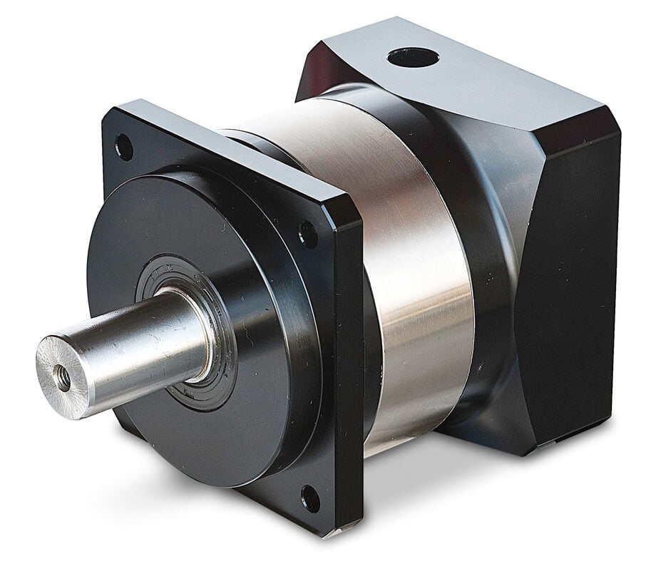
How Does a Planetary Gearbox Work?
Quick Answer
A planetary gearbox (epicyclic gearbox) transmits torque through a central sun gear that drives 2–5 planet gears rolling inside a fixed outer ring gear; the planet carrier becomes the output shaft. Because the load is shared across several simultaneous mesh points, it delivers very high torque density and coaxial input/output in a compact housing. For the common fixed-ring layout the ratio is i = 1 + (Zring / Zsun), and efficiency runs 95–99% per stage. Use one wherever you need a large reduction in a small envelope — servo axes, robots, automotive transmissions, and wind turbines.
What Is a Planetary Gearbox?
An epicyclic (planetary) gear set has four functional elements sharing one central axis:
- Sun gear — the central gear, normally the high-speed input from the motor.
- Planet gears — typically three gears that mesh with the sun on their inside and the ring on their outside, mounted on the carrier.
- Ring gear (annulus) — the internally-toothed outer ring; in a standard reducer it is fixed to the housing.
- Planet carrier — the arm holding the planet axles; in a standard reducer it is the output.
The tooth counts are geometrically linked: Zring = Zsun + 2 · Zplanet. The “planetary” name comes from the planets orbiting the sun while spinning on their own axes — exactly like the solar system.
How a Planetary Gearbox Works — Step by Step
- The motor drives the sun gear at high speed, low torque.
- The sun meshes simultaneously with all planet gears, so each planet carries only its share of the load.
- Because the ring gear is fixed, the planets cannot spin in place — they are forced to orbit the sun while rotating on their own pins.
- The planet carrier connects those pins, so it rotates in the same direction as the sun but at reduced speed.
- Torque is multiplied by roughly the gear ratio (minus efficiency loss); speed is divided by the same ratio.
- By choosing which element is fixed, input, or output, the same set yields six transmission behaviours (reduction, overdrive, differential, reverse, etc.).
The six power-flow configurations
The same physical set produces six behaviours because any one of the three elements (sun, ring, carrier) can be the fixed reaction member, and either of the remaining two can be input or output. The most common is sun input → ring fixed → carrier output (speed reduction, torque multiplication, same direction). Other arrangements give overdrive (carrier input, ring fixed, sun output), reverse (ring input, sun fixed, carrier output — direction flips), or differential action (two elements driven, third is the difference) used in automotive final drives. For a reducer you almost always want the ring grounded; the other five exist mainly for transmissions and differentials.
Planetary vs Other Gearbox Types
| Attribute | Planetary | Spur / Helical | Worm | Harmonic |
|---|---|---|---|---|
| Torque density | Very high (load shared) | Moderate (single mesh) | Low–moderate | Very high |
| Efficiency / stage | 95–99% | 96–99% | 50–90% (lead-angle dependent) | 65–90% |
| Single-stage ratio | 3:1 – 10:1 | 1:1 – 6:1 | 5:1 – 100:1 | 30:1 – 320:1 |
| Shaft alignment | Coaxial (inline) | Parallel offset | Right-angle | Coaxial |
| Backlash | 1–15 arc-min | 3–10 arc-min | 10–60 arc-min | <1 arc-min (near zero) |
| Self-locking | No | No | Yes (high ratio) | No |
| Size for same torque | Smallest | Medium | Largest | Small |
For a deeper type-vs-type breakdown, see our harmonic drive vs planetary gear and gearbox vs gear motor guides.
Engineering Data: Ratios, Efficiency, and Torque Formulas
The Willis equation (ratio)
For the fixed-ring / sun-input / carrier-output arrangement, the fundamental planetary relation (Willis equation) reduces to:
i = 1 + (Zring / Zsun)
Example: Zring = 96, Zsun = 24 → i = 1 + 4 = 5:1. Planet tooth count does not enter the ratio — it sets load sharing and balance only. Multi-stage units multiply: itotal = i1 × i2 × i3.
Torque, speed, and efficiency
Output torque and speed follow directly from the ratio and per-stage efficiency η:
Tout = Tin × i × η (per stage)
nout = nin / i
ηtotal = η1 × η2 × … (each stage ~0.95–0.99)
Efficiency, temperature, and backlash limits
| Parameter | Typical planetary value | Standard / note |
|---|---|---|
| Efficiency per stage | 95–99% | Drops ~3–5% per stage added |
| Max single-stage ratio | ~10:1 | Zsun ≥ 12 (undercut limit) caps it |
| Backlash (standard / precision) | 5–15 / <3 arc-min | ISO 1328 class drives tolerance |
| Lubricant temperature limit | −10 °C to +90 °C | AGMA / ISO service factor |
| Grease life vs temperature | Halves per ~10 °C over rated | SKF bearing-life methodology |
| Load capacity basis | AGMA 2001 / ISO 6336 | Bending & contact stress rating |
Multi-stage stacking and the AGMA service factor
Because one stage caps near 10:1, high reductions are built by stacking stages in series, each in its own carrier/ring nest. The ratio multiplies, but so does the loss: a 50:1 unit of 10:1 × 5:1 loses ~3–5% on each stage, landing near 90–94% total. Backlash also accumulates — three standard stages can sum to 30+ arc-min, which is why precision servo units use tight-grade gears in every stage rather than one.
For durability, size the box with an AGMA service factor (or ISO equivalent) that multiplies the nominal load by duty, hours/day, shock, and ambient. A continuous 24/7 conveyor at moderate shock might need SF ≈ 1.25; an intermittent hoist with hard starts needs SF ≈ 1.5–2.0. Undersizing here is the most common cause of premature tooth bending fatigue (rated by AGMA 2001 / ISO 6336 allowable stress), not the ratio math.
Best Applications for a Planetary Gearbox
| Application | Why planetary fits |
|---|---|
| Robotics & servo axes | High torque density, low backlash, coaxial |
| CNC machines | Precision positioning, rigid drive train |
| Automotive transmissions | Ratio switching without power interruption |
| Wind turbines | Compact step-up of multi-MW rotor torque |
| Medical & semiconductor | Quiet, precise, small footprint |
| AGVs & conveyors | Continuous-duty torque multiplication |
Pair a planetary reducer with a motor via our speed-reducer guide and motor flange guide.
Planetary Gearbox Types You Will Encounter
Beyond the inline coaxial layout, several variants matter for selection:
- Inline (coaxial) planetary — input and output share one axis; the default for servo and BLDC reducers.
- Right-angle planetary — a bevel or worm stage on the output bends the shaft 90°; used where space forbids a straight-line drivetrain.
- Spur-tooth vs helical-tooth planets — spur is cheaper and lower-loss but noisier at speed; helical runs quieter and carries more load but generates axial thrust the bearings must absorb.
- Shaft-output vs housing-output — in a wheel-hub or cycloidal neighbour, the ring or carrier can be the rotating member instead of the shaft, turning the gearbox into a torque hub.
Why planetary wins the torque-density contest
The torque-density advantage is not magic — it is geometry. In a parallel-shaft spur reducer, only one tooth pair carries the load at any instant, so the housing must be large enough for that single mesh to survive. In a planetary set, the sun’s torque is split across three or more planet meshes simultaneously, so each contact sees roughly 1/N of the total.
The reactive forces from the planets also cancel radially at the carrier, so the shafts see almost pure torque with little bending — that is why a planetary unit of a given output torque is typically 30–50% smaller and lighter than the equivalent spur or helical box, and why it is the default where mass and envelope are constrained (robot joints, drone gimbals, in-wheel drives).
Step-by-Step Selection (with Worked Example)
Selection checklist
- Define the motion: motor speed (rpm), required output speed, and output torque.
- Compute the ratio: i = nin / nout. If >10:1, plan two or more stages.
- Check torque with efficiency: Tout = Tin × i × ηtotal; add 20–30% margin.
- Pick backlash grade: <3 arc-min for servo positioning, standard for conveyors.
- Confirm thermal/lube envelope (AGMA service factor) for duty and ambient.
Worked example
Requirement: a servo axis with a 0.5 N·m motor at 3000 rpm must deliver 20 N·m at 60 rpm.
- Ratio: i = 3000 / 60 = 50:1. Single-stage maxes at ~10:1, so use two stages: 10:1 × 5:1.
- Efficiency: ηtotal = 0.97 × 0.97 = 0.941.
- Output torque: Tout = 0.5 × 50 × 0.941 = 23.5 N·m ≥ 20 N·m — margin ~18%.
- Output speed: 3000 / 50 = 60 rpm — exact match.
- Backlash: select <3 arc-min precision grade for repeatable positioning.
Verdict: a 2-stage planetary 50:1 precision unit fits with margin. A single stage cannot reach 50:1.
A second, contrasting case shows the limit of the architecture: if the same axis needed 200:1, two stages (10:1 × 20:1) would already cost ~10% in efficiency and stack backlash to ~20 arc-min — at that point a harmonic drive (single-stage 200:1, near-zero backlash) or a worm (self-locking) becomes the stronger pick despite lower efficiency. The planetary’s sweet spot is genuinely the 3:1–100:1 band; outside it, pick on the trade you can tolerate (efficiency vs backlash vs self-lock), not on habit.
Quick decision matrix
| If you need… | Choose |
|---|---|
| 3:1–100:1, compact, coaxial, efficient | Planetary |
| Zero backlash, >30:1 single stage | Harmonic |
| Self-locking, right-angle, cheap | Worm |
| >100:1 in one envelope with high efficiency | Planetary stacked 3+ stages (watch efficiency) |
Counter-intuitive takeaway: planetary compactness is a single-stage luxury. Past ~3 stages the stacked efficiency loss (~3–5% each) and backlash accumulation erode the very advantage you bought it for — at extreme ratios a harmonic or worm can win on ratio-per-envelope. Also, “more planets = more torque” plateaus at three: 4–5 planets demand equal load-sharing and tighter tolerances, or you get uneven wear and noise.
Common Engineering Mistakes
- Assuming one stage reaches 50:1. Single-stage planetary is capped near 10:1 by tooth-undercut limits; you must stack stages.
- Using standard backlash for a servo. A 10 arc-min unit drifts; pick <3 arc-min for positioning axes.
- Ignoring the thermal envelope. Grease life roughly halves per 10 °C over rating — a hot, high-ratio stack fails early.
- Mis-mounting the carrier. In a standard reducer the carrier must rotate freely; bolting it down kills the reduction.
- Forgetting radial load on planet pins. Size bearings to SKF L10; overload cracks the carrier.
- Expecting self-locking. Planetary does not self-lock — add a brake or use a worm where hold-still matters.
Troubleshooting: Problem → Cause → Solution
Most planetary failures trace to three root causes: wrong ratio architecture (asking one stage to do what only stacked stages can), undersized bearings/gears relative to the AGMA service factor, and backlash grade mismatched to the control loop. The table below maps the symptoms engineers actually see in the field to the physical cause and the fix — use it during commissioning rather than after a line goes down.
| Problem | Cause | Solution |
|---|---|---|
| Excessive backlash / position drift | Wrong backlash grade or worn gears | Reselect <3 arc-min precision grade; replace worn set |
| Noise or vibration | Misalignment, damaged planet, resonance | Realign shafts; inspect planet teeth; damp resonance |
| Overheating | Overload, poor lube, multi-stage eff. loss | Derate, improve cooling, verify AGMA service factor |
| Oil / grease leakage | Seal failure or overfill | Replace seal, correct fill volume |
| Premature bearing failure | Radial overload, wrong fit | Check SKF L10, resize bearing, correct fit |
| Output slips under load | Carrier not the rotating member / wrong config | Verify fixed-ring config; confirm output member |
Frequently Asked Questions
What is the formula for planetary gear ratio?
For a fixed ring gear, sun input, carrier output: i = 1 + (Zring / Zsun). The planet tooth count sets load sharing but not the ratio. Multi-stage ratios multiply.
Why is a planetary gearbox more efficient than a worm gearbox?
Planetary meshes are rolling-contact spur/helical teeth with low sliding; a worm relies on a high-lead-angle screw sliding against the wheel, shedding 10–50% as heat. Well-built planetary runs 95–99% per stage versus 50–90% for worm.
Can a planetary gearbox self-lock?
No. A planetary set back-drives freely because it has no screw wedge. If you need to hold position without power or braking, use a worm (high ratio) or add a brake — see our worm gear reducer guide.
How many planets should a planetary gearbox have?
Three is the standard sweet spot — symmetric load sharing and balance. Four or five planets raise torque capacity only if manufacturing holds equal spacing and tooth accuracy; otherwise wear becomes uneven.
What backlash do I need for a servo axis?
Precision servo positioning wants <3 arc-min (often <1). Conveyors and simple speed reduction tolerate 5–15 arc-min. Specifying tighter than needed only adds cost.
Planetary or harmonic — which for robotics?
Use planetary for 3:1–100:1 coaxial torque with good efficiency and moderate backlash; use harmonic when you need near-zero backlash and a very high single-stage ratio in a flat package (e.g., robot wrist joints).
Why Choose Greensky for Planetary Gearboxes?
Greensky Power builds planetary gear motors (inline and right-angle), DC planetary gear motors, and harmonic drive assemblies, so we recommend the architecture that fits your duty rather than pushing one technology. All units meet IEC 60034-1 motor performance and are available in IE3/IE4 classes; ratios, backlash grades, and mounting flanges are built to standard interfaces at low MOQ. Our R&D team delivers custom ratios and motor integrations in 4–6 weeks — request a custom quote → or contact our engineering team.
Related Resources
- Harmonic drive vs planetary gear — type-level selection
- Gearbox vs gear motor — what to specify
- Worm gear reducer explained — self-locking alternative
- Everything about worm gears — efficiency & load capacity
- Why robot arms need speed reducers
- Motor features hub — all four motor topologies
- Stepper motors — pairing with planetary reducers
- Our gear-motor manufacturing capabilities
References
- IEC 60034-1:2022 — Rotating electrical machines, Part 1: Rating and performance. webstore.iec.ch/publication/64888
- IEC 60034-30-1 — Efficiency classes for rotating electrical machines (IE1–IE5). webstore.iec.ch/publication/67563
- NEMA MG 1-2024 — Motors and Generators. nema.org/standards/view/Motors-and-Generators
- AGMA 2001 / AGMA 6034 — Gear rating and enclosed gear unit practice. agma.org/standards
- ISO 6336 — Calculation of load capacity of spur and helical gears. iso.org/standard/76425.html
- ISO 1328 — Cylindrical gear — ISO tooth tolerance system. iso.org/standard/76414.html
- IEEE 112 — Test Procedure for Polyphase Induction & DC Motors. standards.ieee.org/ieee/112/4703
- U.S. DOE — Motor & Drive Systems Efficiency. energy.gov/eere/motors
- SKF — Bearing life calculation (L10) for gear applications. skf.com/group/technical-insights/bearings
- Siemens — SIMOGEAR geared motors technical catalog. assets.new.siemens.com/…/simogear
- maxon — Gear Technology (download). maxongroup.com/…/gear-download
- FAULHABER — Drive technology know-how. faulhaber.com/en/know-how
