
Brushless dc motors applications solution: From Load Profile to Matched Solution
Quick Answer
A brushless DC (BLDC) motor application solution is the matched set of motor, controller, feedback and gearbox that meets one specific load requirement. What decides the design is rarely which BLDC motor is best; it is the torque-speed profile the application presents. Most industrial loads fall into one of five profiles: constant torque, constant power, quadratic (fan or pump), positioning, and high breakaway. Size on continuous torque to stay inside the winding’s thermal limit, on peak torque to prove the acceleration, and pick feedback from the slowest speed the axis has to hold. Typical industrial units span 24–48 V DC, 100 W to 3 kW, at 85–95% efficiency at the design point.
- What Is a Brushless DC Motor?
- How a BLDC Motor Produces Motion
- What a BLDC Motor Application Solution Actually Means
- The Five Load Profiles That Decide Your Solution
- Application Solution Matrix: Industry by Industry
- Sizing a BLDC Motor: A Reproducible Worked Example
- Choosing the Control Architecture
- Common Engineering Mistakes
- Troubleshooting BLDC Application Problems
- Why Choose Greensky Power
- Related Resources
- References
- FAQ
What Is a Brushless DC Motor?
A brushless DC motor is a permanent-magnet synchronous machine driven by an electronic controller rather than mechanical brushes and a commutator. The magnets sit on the rotor, the windings on the stator, and a power-electronic stage switches current through those windings in sequence as the rotor turns. Nothing in the assembly rubs against anything else, so there is no brush dust to shed and no commutator to re-cut. The brush replacement interval that dominates a brushed motor’s maintenance cost does not exist here.
Set against a brushed DC motor, a BLDC design eliminates both of the wear mechanisms that normally set life: brush erosion and commutator erosion. Service life therefore stretches from a few thousand hours to 10,000–50,000 hours, the exact figure depending on bearings and duty, while efficiency at the design point rises from roughly 75–85% to 85–95%. Readers new to the category will find the construction described in the BLDC basics overview, and the two families compared side by side in brush vs brushless DC motors. The rating framework behind those efficiency figures is set out in electric motor basics, and the efficiency classification itself in motor efficiency classes.
The Four Parts of Every BLDC Solution
An “application solution” is never just a motor. It is a matched set, and the matching has to happen across four elements.
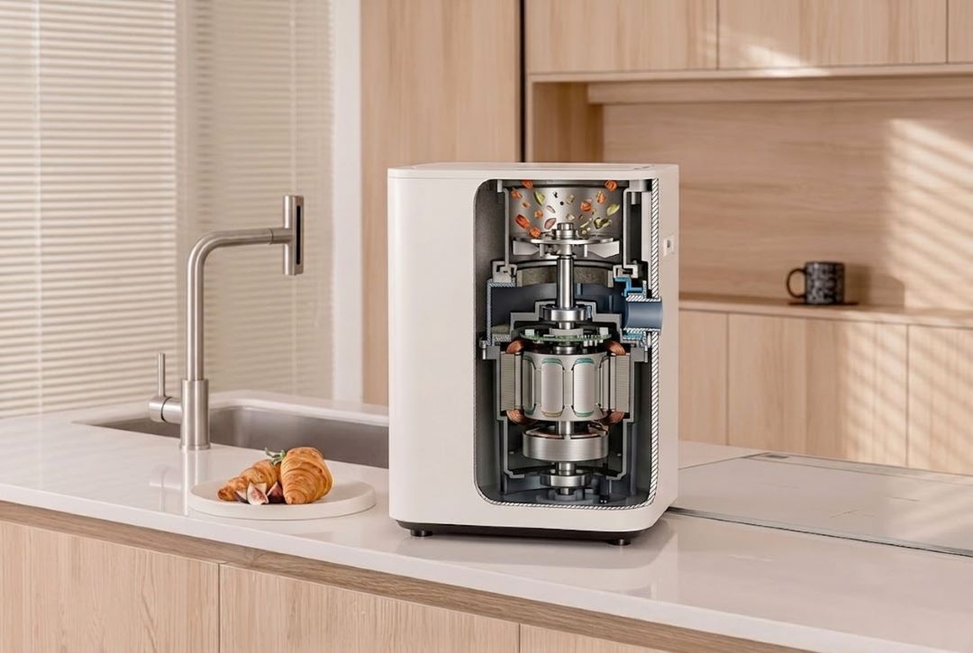
The motor itself may be inner-rotor or outer-rotor, and it is sized by continuous and peak torque at the shaft speed the machine needs. Behind it sits the controller, the electronic drive that carries out commutation, limits current and regulates speed. The feedback element supplies rotor position, whether from Hall sensors, an encoder or sensorless back-EMF estimation, and it is chosen from the slowest speed the axis has to control. The transmission is either direct drive or a brushless DC gear motor when the load needs more torque at lower speed than the motor can produce on its own.
How a BLDC Motor Produces Motion
The operating principle is electromagnetic. The controller energises stator phases in a fixed sequence, which produces a rotating magnetic field, and the permanent-magnet rotor follows that field. Industrial practice splits into two commutation strategies, and the one you pick shows up directly in torque quality.
Six-Step (Trapezoidal) Commutation
In six-step commutation the drive energises two of the three phases at a time and switches every 60 electrical degrees. The scheme is simple to implement and hard to get wrong, which is why it suits motors with a trapezoidal back-EMF waveform. Its cost is torque ripple at every commutation event. In the ideal case that ripple reaches roughly 14%, and it appears at the machine as low-frequency vibration and audible noise.
Field-Oriented Control (FOC)
FOC transforms the three measured phase currents into a rotating d-q reference frame aligned with the rotor flux, regulates the direct-axis current to zero, and uses the quadrature-axis current to set torque. Torque ripple falls below 1%, and efficiency gains a little because current is delivered in phase with the back-EMF. The price is a faster microcontroller, current sensing on at least two phases, and a trustworthy rotor position signal from Hall sensors, an encoder or an observer algorithm. The drive hardware that carries this out is examined in the motor controller guide.
| Commutation | Torque ripple | Typical efficiency | Hardware cost | Where it fits |
|---|---|---|---|---|
| Six-step (trapezoidal) | ~14% | Good | Low | Pumps, fans, basic conveyors, cost-sensitive drives |
| FOC / sinusoidal | <1% | Excellent | Medium-higher | Robotics, e-mobility, quiet appliances, precision actuators |
| Direct torque control (DTC) | <2% | Excellent | Higher | Heavy traction and demanding industrial drives |
A BLDC motor and a PMSM are, physically, nearly the same machine; both are three-phase permanent-magnet motors. What separates the labels is the back-EMF shape, trapezoidal for six-step and sinusoidal for FOC. Drive a “BLDC” motor from an FOC controller and it behaves as a PMSM, so the thing worth specifying is the set of electrical constants (Ke, Kt, R, L), not the label.
What a BLDC Motor Application Solution Actually Means
The phrase “BLDC motor applications solution” gets used loosely in marketing copy. Engineering usage is narrower: it means the mapping from a requirement to a hardware set, and that mapping is only as good as its inputs. Four of them do most of the work, and they are worth pinning down before anyone opens a catalogue:
- Torque demand at the shaft: friction, gravity on an incline, and the acceleration of every reflected inertia.
- Speed range: the minimum speed at which the axis must be controlled, and the maximum speed at the load.
- Duty cycle: the proportion of time at rated load, and the ambient temperature inside the enclosure.
- Environment and interface: ingress protection, washdown or sterilisation, and the control signals the machine’s PLC expects.
Voltage, frame size, rotor type and gearbox ratio all follow from those four answers. It is also why a request that arrives as a single wattage figure (“I need a 400 W BLDC motor”) tends to come back for rework. Wattage on its own says nothing about whether the motor will overheat, stall under load or overshoot its position target.
The Five Load Profiles That Decide Your Solution
Nearly every BLDC application reduces to one of five torque-speed profiles. Naming the profile first narrows the rest of the design, because each one loads a different part of the motor’s capability.
| Load profile | Torque vs. speed | Typical applications | Sizing priority |
|---|---|---|---|
| Constant torque | Flat across the whole speed range | Belt conveyors, extruders, positive-displacement pumps, screw drives | Continuous torque and thermal headroom |
| Constant power | Falls roughly as 1/ω above base speed | Winding and unwinding, machine-tool spindles, traction above base speed | Base speed plus field-weakening range |
| Quadratic (fan/pump) | Rises with the square of speed | Centrifugal fans, blowers, centrifugal pumps | Affinity laws: avoid oversizing |
| Positioning / indexing | High acceleration torque, then dwell | CNC axes, packaging, pick-and-place, robotics | Peak torque and inertia matching |
| High breakaway | High static torque, then low running torque | Gate operators, valve actuators, mixers, screw feeders | Starting torque margin |
Two of these profiles are easy to get wrong. Take a quadratic load first: torque at half speed is only a quarter of the torque at full speed, so a motor sized on the full-speed point ends up badly oversized at the duty point most installations actually run at. A positioning load is the other trap, and it works the opposite way, because the motor is chosen by acceleration torque rather than running torque, and acceleration torque often runs three to five times higher. The worked example below puts numbers on that. The formulas themselves are collected in how to calculate motor torque, and the wider decision process in selecting a motor for an industrial application.
Application Solution Matrix: Industry by Industry
The table below maps the most common BLDC motor applications onto the specification envelope that usually satisfies them. Read the numbers as a first-pass starting point and confirm them against the real duty cycle, ambient temperature and available cooling.
| Industry | Typical bus voltage | Typical rated power | Preferred rotor | Feedback / control | Design note |
|---|---|---|---|---|---|
| Industrial automation | 24–48 V DC | 100 W–2 kW | Inner rotor | FOC with Hall sensors | Continuous duty; heat path through the mounting flange |
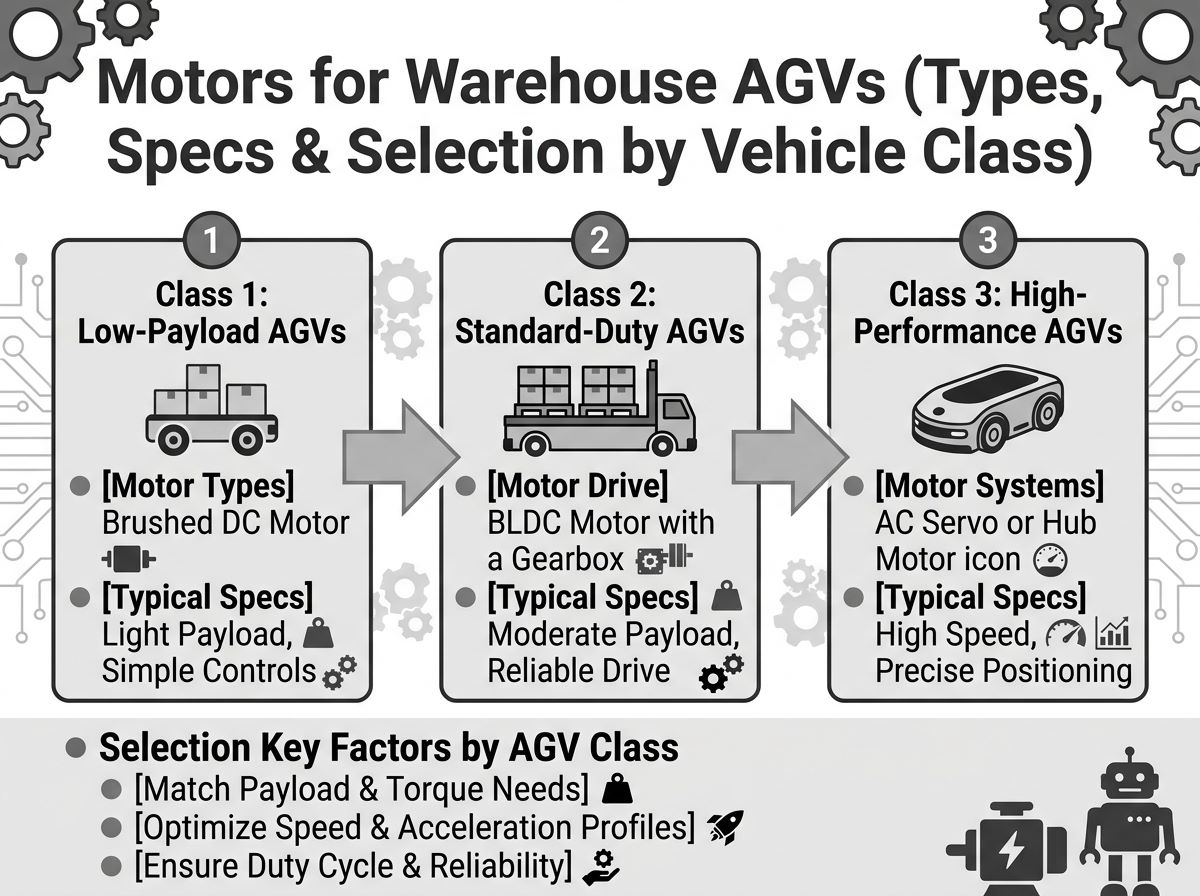
| Robotics and AGV | 24–48 V DC | 100 W–3 kW | Inner rotor + planetary gearbox | FOC with encoder | Backdrivability and torque estimation from current |
| Automotive auxiliary | 12–48 V DC | 50–500 W | Inner rotor | Six-step with Hall sensors | EPS, seat and HVAC blower actuators; wide temperature range |
| E-mobility and light EVs | 36–72 V DC | 250 W–3 kW | Outer rotor (hub) | FOC, often sensorless | Regenerative braking compatibility |
| Medical and laboratory | 12–24 V DC | 5–100 W | Slotless / coreless | Encoder or high-resolution Hall | Low noise, low vibration, autoclavable options |
| HVAC and fluid handling | 24–310 V DC | 50 W–1 kW | Outer rotor | Sensorless FOC | Variable-speed duty; verify fluid material compatibility |
| Lawn, garden and power tools | 18–60 V DC | 100 W–2 kW | Outer rotor | Sensorless six-step | High power density, intermittent duty |
One mechanical choice cuts across every row: whether the axis is direct drive or geared. A direct-drive motor vs gear motor comparison sets out the trade-off between simplicity and torque density. The other is whether the motor can be integrated with its controller, a question the BLDC motor controller guide takes further.
Sizing a BLDC Motor: A Reproducible Worked Example
This example sizes a traction motor for a small automated guided vehicle (AGV). Every figure is worked from first principles, so you can drop your own numbers in and re-run the arithmetic.
Step 1: Define the requirement
Vehicle mass including payload m = 400 kg. Wheel radius r = 0.075 m. Target cruise speed v = 1.2 m/s. Required acceleration a = 0.5 m/s². Rolling-resistance coefficient C_rr = 0.015. Single-stage planetary ratio i = 20. Drivetrain efficiency η = 0.85. Level floor, so no grade force.
Step 2: Convert the load to a force at the wheel
Rolling resistance: F_rr = C_rr × m × g = 0.015 × 400 × 9.81 = 58.9 N.
Acceleration force: F_a = m × a = 400 × 0.5 = 200 N.
Peak tractive force: F_total = 58.9 + 200 = 258.9 N.
Step 3: Convert force to wheel torque and speed
Wheel torque: T_wheel = F_total × r = 258.9 × 0.075 = 19.4 N·m.
Wheel speed: ω_wheel = v / r = 1.2 / 0.075 = 16 rad/s = 152.8 rpm.
Step 4: Reflect through the gearbox to the motor shaft
Motor speed: ω_motor = 152.8 × 20 = 3,056 rpm.
Motor torque: T_motor = T_wheel / (i × η) = 19.4 / (20 × 0.85) = 1.14 N·m.
Step 5: Separate peak from continuous duty
During acceleration the motor must deliver 1.14 N·m at 3,056 rpm, which is P = T × ω = 1.14 × 320 = 365 W.
At steady cruise the acceleration term disappears, so the tractive force is only the rolling term: T_motor(cruise) = (58.9 × 0.075) / (20 × 0.85) = 0.26 N·m, or about 83 W.
| Quantity | Value | Basis |
|---|---|---|
| Peak tractive force | 258.9 N | Rolling 58.9 N + acceleration 200 N |
| Wheel torque at peak | 19.4 N·m | 258.9 N × 0.075 m |
| Wheel speed at cruise | 152.8 rpm | 1.2 m/s ÷ 0.075 m |
| Motor speed | 3,056 rpm | 152.8 rpm × 20 |
| Motor torque, acceleration phase | 1.14 N·m | 19.4 ÷ (20 × 0.85) |
| Motor torque, cruise phase | 0.26 N·m | Rolling load only |
| Peak mechanical power | 365 W | 1.14 N·m × 320 rad/s |
| Continuous mechanical power | 83 W | 0.26 N·m × 320 rad/s |
Step 6: Pick the motor and check current
Choose a 48 V, 400 W inner-rotor BLDC motor rated 1.25 N·m at 3,000 rpm. Peak demand of 1.14 N·m sits below the rated torque, and the continuous demand of 0.26 N·m leaves a wide margin to the insulation limit. The margin is deliberate rather than accidental, because AGVs accelerate in short bursts and then spend most of their time at cruise.
Now convert the speed constant to a torque constant to size the controller current. For a motor with K_v = 100 rpm/V, the torque constant is K_t ≈ 9.549 / K_v = 0.095 N·m/A. Peak current is therefore 1.14 / 0.095 ≈ 12 A, so a 48 V controller rated 20 A continuous covers it comfortably.
Choosing the Control Architecture
One question settles the feedback choice: what is the lowest speed at which the axis must produce smooth, controlled torque? Back-EMF-based sensorless control degrades as speed approaches zero, because there is nothing left to observe. Any axis that has to hold a load at standstill, or start smoothly while loaded, therefore needs a physical position sensor.
| Feedback method | Signals | Low-speed behaviour | Relative cost | Best fit |
|---|---|---|---|---|
| Sensorless (back-EMF observer) | None | Poor below roughly 5% of rated speed | Lowest | Fans, centrifugal pumps, propellers, free-spinning axes |
| Hall sensors (six-step or FOC) | 3 digital | Reliable start-up and practical low-speed commutation | Low | Conveyors, actuators, cost-sensitive automation |
| Incremental encoder | A/B/Z quadrature | Very good speed regulation | Medium | Indexing, speed-controlled axes, packaging |
| Absolute encoder or resolver | Serial or analog | Excellent down to zero speed with position hold | Higher | Robotics, machine tools, precision positioning |
A gearbox becomes necessary when the torque requirement exceeds what the motor can deliver at the required speed. A planetary reduction stage multiplies torque by the ratio while giving up only 3–5% per stage; the companion guide on how a planetary gearbox works explains the geometry, and speed-reducer selection covers the service-factor correction that matters once the load is shock-loaded. Matched packages are common on mobile equipment: see 48 V AGV motors and OEM HVAC motor assemblies.
Common Engineering Mistakes
- Sizing on wattage alone. A 400 W motor at 1,000 rpm and a 400 W motor at 6,000 rpm are different machines, and wattage without a speed and torque point is not a specification.
- Confusing peak and continuous torque. Peak is limited by magnetic saturation and by the controller’s current ceiling; continuous is limited by winding temperature. Design to continuous, then verify peak.
- The enclosure is easy to forget. The same motor rated for continuous duty in open air derates sharply inside a sealed housing, so the thermal path has to be confirmed before the datasheet is trusted.
- A holding axis driven by sensorless control will not behave. Without back-EMF there is no stable low-speed operation, and the axis cogs or stalls at start-up.
- Forgetting reflected inertia. A gearbox divides load inertia by the square of the ratio, which helps, but a high-ratio unit also magnifies rotor inertia reflected back to the load and costs bandwidth.
- Testing only at no load proves very little. A motor that passes a no-load check can still stall under a loaded belt. Run the complete motor-controller pair on the real load for at least one full duty cycle.
Troubleshooting BLDC Application Problems
Most BLDC problems surface as one of a handful of symptoms, and the symptom usually points at the control loop before it points at the motor. The table pairs the common ones with the cause to check first and the correction that normally clears them.
| Symptom | Likely cause | Corrective action |
|---|---|---|
| Motor stalls at start-up under load | Sensorless control with insufficient start-up torque; current limit set too low | Move to Hall sensors or an encoder; raise the controller current limit within winding limits |
| Overheating at rated load | Continuous torque exceeded; blocked thermal path; ambient too high | Re-check continuous torque after derating; improve mounting heat transfer; reduce duty cycle |
| Audible whine or vibration at low speed | Six-step commutation torque ripple; mechanical resonance in the frame | Switch to FOC; change the mounting stiffness or add a compliant coupling |
| Speed droops as load increases | Current limit reached; bus voltage sagging under load | Verify supply can hold rated voltage; check wiring gauge and connector contact resistance |
| Cogging felt when turning by hand | Magnet-to-tooth detent torque, worst at certain slot/pole combinations | Choose a skewed-slot or well-matched slot/pole design; residual cogging is largely compensated by FOC |
| Controller trips on overcurrent at random | Acceleration ramp too aggressive; reflected inertia too high | Lengthen the acceleration profile; verify gearbox ratio against load inertia |
Why Choose Greensky Power
Greensky Power designs and manufactures brushless DC motors and matched BLDC gear motors for OEM equipment builders, concentrating on the compact, low-power, low-flow end of the market that larger motor houses tend to deprioritise. Applications are quoted from real load data (torque, speed, duty cycle and ambient), not from a catalogue wattage. The range covers 24 V and 48 V inner-rotor units, outer-rotor fans and hubs, and geared assemblies with planetary or right-angle outputs, each available with Hall sensors, encoders or a sensorless controller.
Buyers building a new platform can use the custom brushless DC motors programme for winding, shaft, flange and cable customisation, or the OEM partnership route, which adds volume pricing, PPAP-style documentation and long-term supply commitments. Ready-made units are listed under brushless DC motors.
Related Resources
- How brushless DC electric motors work covers the motor-side fundamentals.
- How to select a motor for an industrial application sets out the wider selection framework.
- How to calculate motor torque gives the formulas behind the worked example.
- Applications of BLDC motors by industry is the companion industry-by-industry drill-down.
- For the demand side, see Top 10 popular BLDC motor application markets.
- Disadvantages of brushless DC motors covers what to weigh against the benefits.
- 24 V brushless DC motors and BLDC planetary gear motors are example product families.
- Brushless DC motors for industrial use covers the continuous-duty industrial class.
- BLDC flat gear motors are compact geared options for tight envelopes.
- 24 V DC brushless gear motors cover volume supply programmes.
- Difference between brush and brushless DC motors gives the comparison in detail.
- Top BLDC motor manufacturers is a guide to shortlisting and evaluating suppliers.
- Custom electric motors is for when a catalogue part will not fit.
References
- International Electrotechnical Commission. (2022). IEC 60034-1: Rotating electrical machines – Part 1: Rating and performance. https://webstore.iec.ch/en/publication/65446
- International Electrotechnical Commission. (2014). IEC 60034-30-1: Efficiency classes of line operated AC motors (IE code). https://webstore.iec.ch/publication/91195
- American National Standards Institute / National Electrical Manufacturers Association. (2021). ANSI/NEMA MG 1: Motors and Generators. https://webstore.ansi.org/standards/nema/ansinemamg2021
- U.S. Department of Energy. (2014). Improving Motor and Drive System Performance: A Sourcebook for Industry. https://www.energy.gov/sites/prod/files/2014/04/f15/10097517.pdf
- International Energy Agency. (2025). Electric motors – Energy System. https://www.iea.org/energy-system/industry/electric-motors
- National Electrical Manufacturers Association. (2024). Motors and Generators. https://www.nema.org/products/pages/motor-and-generator.aspx
- maxon group. (2025). EC technology – brushless DC motor design. https://www.maxongroup.com/maxon/view/content/ec-technology
- FAULHABER. (2025). Drive systems know-how. https://www.faulhaber.com/en/know-how/
- IEEE. (2012). Extended field weakening and overvoltage protection for low-voltage motor drives. IEEE Xplore. https://ieeexplore.ieee.org/document/6342334
- SKF. (2024). Bearing failures and their causes. https://www.skf.com/group/support/bearing-failures-and-their-causes
- Siemens. (2025). Electric motors – SIMOTICS. https://www.siemens.com/global/en/products/drives/electric-motors.html
- International Electrotechnical Commission. (2013). IEC 60529: Degrees of protection provided by enclosures (IP Code). https://www.iec.ch/standards-and-education/standards/iec-60529
- Tsubakimoto Chain Co. (2024). Technical reference: gear motor selection and service factors. https://en.tt-net.tsubakimoto.co.jp/tecs/engd/gen/engd_gen_ggm_sry.asp
- Yaskawa Electric Corporation. (2025). Technical documentation and downloads. https://www.yaskawa.com/downloads/search-index
FAQ
What are the main applications of a BLDC motor?
BLDC motors turn up wherever a compact, efficient and electronically controlled drive is needed: industrial automation and conveyors, robotics and AGVs, automotive auxiliary systems such as electric power steering and blowers, e-mobility and light EVs, medical and laboratory devices, HVAC and fluid handling, and battery-powered lawn and garden equipment. What these have in common is a need for high efficiency and long life, with speed or position controlled precisely at moderate power.
How do I know what size BLDC motor I need?
Start from four inputs: continuous torque at the shaft, the speed range including the minimum speed you must control, the duty cycle and ambient temperature, and the available bus voltage. To get load torque at the motor shaft, divide by the gear ratio and the drivetrain efficiency. Size on continuous torque afterwards, and check peak (acceleration) torque separately. The AGV example above works through the numbers, ending with a peak torque of 1.14 N·m against a cruise torque of only 0.26 N·m.
What is the difference between sensorless and Hall-sensor BLDC control?
Sensorless control estimates rotor position from the back-EMF the motor generates, which needs no extra wiring and costs less. The catch is that back-EMF fades away near zero speed, so a sensorless motor needs an open-loop start-up ramp and cannot hold position at standstill. Hall sensors supply three digital position signals instead, enough for reliable start-up and practical low-speed commutation. Use sensorless control for fans, pumps and propellers; use Hall sensors or an encoder for any axis that has to start under load or hold a position.
Is a 48 V BLDC motor better than a 24 V one?
For the same mechanical power, a 48 V bus draws half the current of a 24 V bus, and copper loss scales with the square of current. Moving from 24 V to 48 V therefore cuts I²R loss by roughly a factor of four. In return you get a cooler motor, thinner cables, smaller connectors and more continuous torque from the same hardware, at the cost of more expensive power electronics and stricter safety handling.
Why does my BLDC motor overheat even though the wattage rating matches?
Because winding temperature is the limiting quantity, not wattage. Continuous torque is capped by how quickly the winding can shed heat through the housing to ambient. Inside a sealed enclosure, or at a high ambient temperature, the same motor that runs cool on a bench will overheat. The options are to reduce the continuous torque requirement, improve the mounting heat path, lower the duty cycle, or specify a larger frame. Whatever you do, derate the catalogue figure for the cooling you actually have.
Can I run a BLDC motor without a controller?
No. A BLDC motor cannot run from a direct DC supply, because there are no brushes or commutator to reverse the winding current mechanically. Commutation, current regulation and speed control all have to come from an electronic controller. Without the right one the motor does not turn at all, which is one of the most common reasons a replacement motor looks “dead” on arrival.
