
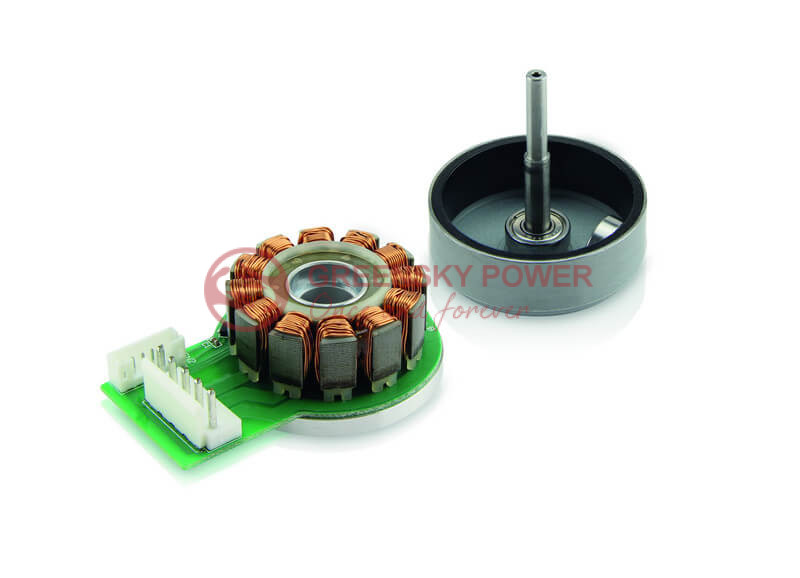
What Are the Disadvantages of Brushless DC Motors?
Quick Answer
The primary disadvantages of brushless DC (BLDC) motors include: (1) higher initial cost due to permanent magnets and electronic controllers—typically 30–60% more than brushed equivalents; (2) controller complexity, requiring electronic speed controllers (ESCs) with Hall sensors or sensorless algorithms that add design and integration effort; (3) electromagnetic interference (EMI) from high-frequency PWM switching, necessitating shielding and filtering per IEC 60034-1 and FCC Part 15; (4) thermal sensitivity, where NdFeB permanent magnets risk irreversible demagnetization above 150–180 °C (IEC 60034-1 Class H limit); and (5) repair difficulty, as integrated electronics make field servicing impractical. Despite these limitations, BLDC motors remain the preferred choice for applications demanding efficiency above 85%, long service life (>10,000 hours), and precise speed control.
What Is a Brushless DC Motor?
A brushless DC motor (BLDC) is a synchronous electric motor powered by DC electricity through an electronic controller that sequentially energizes stator windings to produce a rotating magnetic field. Unlike brushed DC motors, BLDC motors eliminate mechanical brushes and commutators, relying instead on permanent magnets on the rotor and electronic commutation via Hall-effect sensors or back-EMF detection.
According to IEC 60034-1, BLDC motors fall under the classification of permanent-magnet synchronous machines (PMSM), distinct from induction motors and brushed DC motors. The core architecture consists of three main components: a stator with polyphase windings (typically 3-phase), a rotor with permanent magnets (NdFeB, SmCo, or ferrite), and an electronic controller that determines commutation timing based on rotor position feedback.
The U.S. Department of Energy (DOE) recognizes BLDC technology as a key pathway for meeting the IE3 minimum efficiency requirements mandated under 10 CFR Part 431 for general-purpose motors rated 1–500 HP, effective July 2026. This regulatory push has accelerated BLDC adoption in industrial automation, HVAC, and electric vehicle applications.
BLDC vs. Brushed DC vs. Induction Motor Classification
| Parameter | BLDC Motor | Brushed DC Motor | AC Induction Motor |
|---|---|---|---|
| Commutation Method | Electronic (Hall sensors/EMF) | Mechanical (brushes + commutator) | Electromagnetic induction |
| Typical Efficiency | 85–97% | 60–80% | 70–94% |
| Service Life | 10,000+ hours | 1,000–3,000 hours | 15,000–30,000 hours |
| Maintenance Requirements | Low (bearings only) | High (brush replacement) | Low (bearings only) |
| Controller Required | Yes (mandatory) | No (direct DC) | Optional (VFD for speed control) |
| Initial Cost Index | 1.3–1.6× | 1.0× (baseline) | 0.8–1.2× |
| EMI Generation | Medium–High (PWM switching) | High (brush arcing) | Low |
| Speed Control Precision | ±0.1% | ±5% | ±2% (with VFD) |
How BLDC Motors Work: Step-by-Step
Understanding the disadvantages requires first understanding the operating principle. The BLDC motor’s complexity—and its drawbacks—stem directly from this electronic commutation process:
- DC Power Input: A DC voltage source (battery or rectified AC) supplies power to the electronic controller, not directly to the motor windings. The controller acts as an inverter, converting DC into sequentially pulsed three-phase current.
- Rotor Position Detection: Hall-effect sensors installed in the stator detect the rotor’s magnetic pole position at any instant. In sensorless designs, the controller infers position from back-EMF generated in the unenergized phase—but this requires minimum rotational speed (typically 500–1,000 rpm) to function reliably.
- Electronic Commutation: Based on rotor position feedback, the controller energizes the appropriate stator phase winding pair at the precise moment needed to maintain optimal torque angle (90° electrical between stator field and rotor magnet flux). This eliminates the physical brush-commutator contact.
- Torque Generation: The energized stator winding creates a magnetic field that interacts with the rotor’s permanent magnets, producing tangential force and rotational torque. The torque output is proportional to current: T = Kt × I, where Kt is the motor’s torque constant (e.g., 23.6 mNm/A for Faulhaber 2264BP4).
- Speed Regulation: The controller adjusts the PWM duty cycle and commutation frequency to regulate speed and torque. Closed-loop control using encoder feedback can achieve speed precision of ±0.1%, but requires additional sensors, wiring, and controller processing power.
Each step in this process introduces potential failure modes and cost drivers that do not exist in simpler brushed motor designs. The electronic controller, while enabling superior performance, is the single largest source of BLDC disadvantages.
Disadvantages of Brushless DC Motors: Detailed Comparison
1. High Initial Cost
BLDC systems cost 30–60% more than equivalent brushed DC motors. The cost premium comes from two sources:
- Permanent magnet materials: High-grade NdFeB (N42SH–N52SH) magnets cost $60–120/kg, and each motor requires precision-machined magnet arrays. Rare earth price volatility (Nd prices fluctuated 200–400% between 2010–2022) creates supply chain risk.
- Electronic controller: A BLDC ESC adds $15–200+ per unit depending on power rating. For example, the maxon DEC Module 24/2 controller (48W, 8–24V) adds significant cost beyond the motor itself, while industrial-grade controllers from Siemens SIMOTICS series can exceed $500 for high-power applications.
For B2B procurement managers evaluating custom BLDC motor solutions, the total system cost (motor + controller + sensors + wiring) must be compared against lifecycle savings in energy and maintenance. A DOE-commissioned study found that energy savings alone typically recover the cost premium within 2–4 years for continuously operating industrial motors.
2. Controller Complexity and Dependency
BLDC motors cannot operate without an electronic controller. Unlike brushed motors that start instantly when DC power is applied, BLDC motors require:
- Rotor position sensing (Hall sensors, encoders, or back-EMF detection)
- PWM switching logic (typically 20–100 kHz switching frequency)
- Current limiting and thermal protection algorithms
- Commutation timing optimization for different speed/load conditions
maxon’s sensorless control technology illustrates this complexity: their EMF zero-crossing method works only above 500–1,000 rpm, while observer-based methods (enabling FOC/sinusoidal commutation) require several hundred rpm minimum. The magnetic anisotropy method works at standstill but demands motor-specific parameterization—maxon explicitly states “plug and play is not an option” for these controllers.
If the controller fails, the entire motor system becomes non-functional until the controller is repaired or replaced. This contrasts with brushed motors, where a simple power connection restore is sufficient.
3. Electromagnetic Interference (EMI)
The high-frequency PWM switching in BLDC controllers generates significant conducted and radiated EMI. A study published at the IEEE UPEC 2016 conference (DOI: 10.1109/UPEC.2016.8114064) assessed electromagnetic compatibility of BLDC drives in residential air conditioning systems and found that:
- PWM switching at 20–100 kHz produces harmonics extending into the MHz range
- Conducted EMI can exceed CISPR 11/22 Class A limits without proper filtering
- Radiated EMI may interfere with nearby communication equipment and sensitive analog circuits
maxon’s technical documentation recommends several mitigation measures: suppression capacitors between terminals and ground, toroidal ferrite cores on motor leads, shielded paired cables, and grounded motor housings (Faraday cage principle). Each of these adds cost, weight, and design complexity.
4. Thermal Sensitivity and Magnet Demagnetization
BLDC motors use NdFeB permanent magnets that are vulnerable to irreversible demagnetization at elevated temperatures. The IEEE Transactions on Magnetics paper (DOI: 10.1109/TMAG.2015.2456854) by Fasil et al. demonstrated that motor performance varies significantly with magnet temperature, and that the knee point in the demagnetization curve determines the critical operating limit.
| Insulation Class (IEC 60034-1) | Max Winding Temperature | Max Ambient Temperature | Typical BLDC Motor Application |
|---|---|---|---|
| Class A (105°C) | 105°C | 40°C | Consumer electronics fans |
| Class E (120°C) | 120°C | 40°C | Small appliances |
| Class B (130°C) | 130°C | 40°C | General industrial |
| Class F (155°C) | 155°C | 40°C | Industrial automation (maxon EC-max 30) |
| Class H (180°C) | 180°C | 40°C | High-performance (Faulhaber 2668CR: 155°C winding) |
NdFeB magnets typically begin irreversible demagnetization at 150–180°C depending on grade (N-grade: 80°C, SH-grade: 150°C, UH-grade: 180°C). The IEEE ICEMS 2011 paper (DOI: 10.1109/ICEMS.2011.6073588) by Du et al. conducted multiphysics thermal analysis on a 2.2 kW high-speed BLDC motor and confirmed that temperature rise can cause permanent magnet demagnetization and winding insulation damage, necessitating thermal management design from the earliest stages.
Practical data from Faulhaber datasheets illustrates these thermal limits: the 1028S006B BLDC motor has a maximum coil temperature of 125°C and operating temperature range of -20°C to +100°C, while the 2610T012B flat BLDC motor has a more restrictive maximum coil temperature of only 80°C. These thermal constraints directly limit continuous torque output and require derating in high-ambient environments.
5. Difficulty in Repair and Maintenance
BLDC motor repair is fundamentally different from brushed motor repair. Key challenges include:
- Integrated electronics: Controller failures require specialized diagnostic equipment and often complete controller replacement rather than component-level repair.
- Magnet handling: Rotor magnets require careful handling during disassembly; improper procedures can cause magnet damage or demagnetization.
- Specialized knowledge: Technicians must understand both electrical and electronic systems, including PWM control algorithms and sensor calibration procedures.
- Firmware dependency: Controller firmware bugs or parameter mismatches can cause erratic motor behavior that is difficult to diagnose without the manufacturer’s proprietary software tools.
For industrial applications, this means higher downtime costs and longer mean time to repair (MTTR). Greensky Power offers dedicated BLDC motor repair technical support to help minimize these issues.
6. Limited Low-Speed Torque (Sensorless Designs)
Sensorless BLDC motors rely on back-EMF for rotor position detection, which is proportional to rotational speed. At standstill and very low speeds, back-EMF is insufficient for reliable commutation. The IEEE Transactions on Applied Superconductivity paper (DOI: 10.1109/TASC.2018.2792449) by Seo et al. analyzed irreversible demagnetization in BLDC motors with respect to winding connection and current ripple, finding that PWM current ripple can exacerbate demagnetization characteristics, particularly during low-speed operation where current control is less precise.
This limitation makes sensorless BLDC motors unsuitable for applications requiring:
- High starting torque (conveyors, lifting mechanisms)
- Precise positioning at low speed (robotics, CNC machines)
- Smooth torque delivery from zero rpm (medical devices, surgical tools)
7. Sensitivity to Voltage Fluctuations
BLDC controllers are sensitive to supply voltage variations beyond their rated input range. Undervoltage can cause commutation failure and motor stall, while overvoltage can damage switching transistors (MOSFETs/IGBTs). Battery-powered applications face particular challenges as battery voltage varies significantly between charged and discharged states.
8. Environmental Sensitivity
While BLDC motors lack brush wear debris, their electronic components are vulnerable to:
- Moisture and humidity: Controllers require conformal coating or IP65+ enclosures for wet environments
- Dust and contamination: Optical encoders are particularly sensitive to particulate contamination
- Vibration and shock: Solder joints and connector contacts can fatigue under continuous vibration
- Corrosive atmospheres: Salt spray, chemical vapors, and industrial pollutants can degrade electronic components faster than motor windings
Engineering Data: Efficiency, Temperature Limits, and Formulas
BLDC Motor Efficiency by Power Rating
According to IEC 60034-30-1, the efficiency classification for line-operated motors provides a benchmark for BLDC systems. While BLDC motors are not directly classified under IEC 60034-30-1 (which covers line-operated AC motors), the efficiency framework is widely referenced:
| IEC Efficiency Class | Designation | Typical BLDC Efficiency Range | NEMA Equivalent |
|---|---|---|---|
| IE1 | Standard Efficiency | 75–85% | Standard Efficiency |
| IE2 | High Efficiency | 85–90% | Energy Efficient |
| IE3 | Premium Efficiency | 90–94% | NEMA Premium |
| IE4 | Super Premium Efficiency | 94–96% | — |
| IE5 | Ultra Premium Efficiency | 96–97%+ | — |
Reference data: Siemens SIMOTICS 1PH8 series PMSM achieves 92% efficiency at 7.38 kW rated power with 23.5 Nm rated torque. Faulhaber 2668W018CR DC motor achieves 86% maximum efficiency with rare-earth magnet construction.
Key Engineering Formulas for BLDC Disadvantage Analysis
1. Motor Efficiency:
η = (Pout / Pin) × 100% = (T × ω) / (V × I) × 100%
Where: T = output torque (Nm), ω = angular velocity (rad/s), V = supply voltage (V), I = input current (A)
2. Copper Loss (I²R Loss):
Pcu = I² × Rphase × k
Where: k = number of active phases (typically 2 for 3-phase BLDC with 120° conduction). This loss is the primary heat source in the stator windings and directly contributes to thermal limitations.
3. Torque Constant:
Kt = T / I (Nm/A)
Reference: Faulhaber 1028S006B has Kt = 1.76 mNm/A; this constant determines the current required for a given torque output and directly affects controller sizing.
4. Back-EMF Constant:
Ke = Vemf / ω (V·s/rad)
The back-EMF voltage limits the maximum achievable speed at a given supply voltage, as speed increases until back-EMF approaches supply voltage.
5. Thermal Resistance Model:
ΔT = Ploss × (Rth1 + Rth2)
Where: Rth1 = winding-to-housing thermal resistance, Rth2 = housing-to-ambient thermal resistance. Reference: Faulhaber 1028S006B has Rth1 = 6.6 K/W, Rth2 = 42.4 K/W, demonstrating the significant thermal path from winding to ambient.
6. Bearing Life (L10 per SKF/ISO 281):
L10h = (10⁶ / 60n) × (C/P)p
Where: C = dynamic load rating (kN), P = equivalent dynamic load (kN), n = rotational speed (rpm), p = 3 for ball bearings, p = 10/3 for roller bearings. This formula helps evaluate whether bearing life will be a limiting factor in BLDC applications.
NEMA MG 1 Service Factor for BLDC Applications
NEMA MG 1 defines a service factor (SF) that allows motors to operate above nameplate rating under specific conditions. For BLDC motors used in variable-speed applications, NEMA MG 1 Part 30 specifies a typical SF of 1.0–1.15, meaning continuous overload capacity is limited compared to NEMA-design induction motors (SF = 1.15–1.25). This reduced overload margin is a direct consequence of the permanent magnet temperature sensitivity discussed above.
Best Applications for BLDC Motors (Despite Disadvantages)
Despite their drawbacks, BLDC motors excel in applications where their advantages—high efficiency, long life, and precise control—outweigh the cost and complexity penalties:
| Application | Why BLDC Is Preferred | Key Disadvantage Mitigated |
|---|---|---|
| Electric Vehicles & E-bikes | High efficiency (>90%) extends range; regenerative braking; compact size | Cost offset by fuel savings over vehicle lifetime |
| Drones & UAVs | High power-to-weight ratio; instant throttle response | Thermal management via airflow; short flight duration limits heat buildup |
| Industrial Automation & Robotics | Precise positioning; high-speed capability; long maintenance intervals | Industrial-grade controllers with built-in EMI filtering |
| HVAC Systems | Variable-speed operation matches load; meets DOE efficiency mandates | Continuous operation justifies controller cost through energy savings |
| Medical Equipment | Silent operation; sterilizable design; precise speed control | Hermetic sealing protects electronics; sensorless control avoids contamination risk |
Selection Guide: When to Choose (or Avoid) BLDC
Follow this step-by-step process to determine whether a BLDC motor is the right choice for your application:
- Define application requirements: Required torque, speed range, duty cycle, ambient temperature, expected service life, and budget constraints. If service life < 2,000 hours and duty cycle is intermittent, a brushed motor may suffice.
- Evaluate total cost of ownership (TCO): Calculate TCO = initial cost + energy cost + maintenance cost + downtime cost over expected service life. For continuous-duty applications (>4,000 hours/year), BLDC energy savings typically justify the premium.
- Assess controller integration capability: Does your engineering team have experience with motor controller programming, EMI compliance testing, and sensor calibration? If not, consider pre-integrated motor-controller packages.
- Verify thermal margin: Calculate worst-case winding temperature using thermal resistance model. Ensure max winding temperature is at least 20°C below the magnet’s irreversible demagnetization threshold for the selected insulation class.
- Check regulatory compliance: For U.S. markets, verify DOE 10 CFR Part 431 compliance. For industrial applications, confirm NEMA MG 1 conformance. For European markets, ensure CE marking and IEC 60034 compliance.
- Plan for end-of-life: Evaluate repair vs. replace economics. For mission-critical applications, stock spare controllers and motors. For warranty planning, ensure supplier offers adequate coverage (minimum 1 year).
Common Engineering Mistakes When Using BLDC Motors
- Undersizing the controller: Selecting a controller rated only for nominal current without accounting for peak current during acceleration. Peak currents can reach 3–5× rated current, requiring controller ratings of at least 2× the motor’s nominal current.
- Ignoring EMI compliance: Failing to include EMI filtering during initial design, then attempting to retrofit shielding after failing FCC/CISPR compliance testing. This often requires PCB respins and significantly delays product launch.
- Neglecting thermal management: Assuming that because BLDC motors are “more efficient,” they generate less heat. While true at rated load, the concentrated heat in windings and controller MOSFETs requires deliberate thermal paths—especially in enclosed or high-ambient environments.
- Mismatching sensor type to application: Using sensorless control for an application requiring low-speed torque or positioning, then discovering the motor cannot start reliably under load. Sensorless control requires minimum speed for back-EMF detection.
- Overlooking magnet temperature coefficient: Not accounting for the fact that NdFeB magnets lose approximately 0.12%/°C of remanence reversibly, meaning a motor operating at 120°C may deliver 10% less torque than at 20°C. This must be factored into torque margin calculations.
- Inadequate voltage margin: Designing the controller to operate at exactly the battery nominal voltage without accounting for full-charge voltage (which can be 25% higher for Li-ion batteries) and voltage spikes from PWM switching (which can add another 20–30% transient overshoot).
Troubleshooting Table: BLDC Motor Problems
| Problem | Likely Cause | Solution |
|---|---|---|
| Motor fails to start or stutters | Hall sensor misalignment or failure; insufficient back-EMF at low speed (sensorless) | Verify Hall sensor wiring and alignment; use sensored control for low-speed applications; add startup ramp algorithm |
| Excessive motor heating | Current limit set too high; insufficient cooling; blocked ventilation | Reduce current limit; verify thermal resistance path; add forced air cooling or heatsink; check for phase-to-phase short |
| Controller failure / MOSFET burnout | Voltage spikes from PWM switching; inadequate decoupling capacitors; overcurrent events | Add TVS diodes and bulk capacitors; verify dead-time settings; ensure proper gate drive voltage |
| EMI interference with nearby electronics | High-frequency PWM radiation; unshielded motor cables; poor grounding | Use shielded twisted-pair cables; install ferrite cores; improve grounding; reduce PWM frequency if possible |
| Reduced torque after extended operation | Magnet demagnetization from thermal overload; bearing degradation | Check operating temperature vs. magnet grade rating; verify bearing condition; reduce continuous load or improve cooling |
| Erratic speed or position control | Encoder noise; controller tuning issues; electromagnetic interference on feedback signals | Use shielded encoder cables; add signal filtering; retune PID parameters; check for ground loops |
| Motor vibration or acoustic noise | Commutation timing errors; mechanical resonance; current ripple from low PWM frequency | Verify Hall sensor timing; increase PWM frequency above 20 kHz; implement sinusoidal commutation (FOC) |
| Premature bearing failure | Inadequate bearing selection for load/speed; shaft current through bearings (common in VFD-driven motors) | Use insulated bearings or shaft grounding rings; recalculate bearing L10 life per SKF/ISO 281; verify alignment |
FAQ
Are brushless DC motors worth the extra cost?
For applications operating more than 2,000 hours per year where efficiency, reliability, and maintenance-free operation are valued, BLDC motors are worth the premium. The energy savings alone typically recover the cost difference within 2–4 years, and the elimination of brush replacement reduces maintenance labor costs. However, for intermittent-duty or cost-sensitive consumer applications, brushed motors remain more economical.
What is the main disadvantage of a brushless DC motor?
The primary disadvantage is the mandatory electronic controller, which increases initial cost, adds design complexity, creates EMI challenges, and introduces a single point of failure. Without the controller, the motor cannot function at all—unlike brushed motors that operate directly from a DC power source.
How long do brushless DC motors last?
BLDC motors typically last 10,000–20,000+ operating hours, limited primarily by bearing life rather than electrical wear. The SKF bearing L10 life formula (L10h = (10⁶/60n) × (C/P)ᵖ) provides a quantitative estimate. With proper bearing selection and lubrication, service lives exceeding 30,000 hours are achievable in industrial applications.
Can a brushless DC motor run without a controller?
No. BLDC motors require electronic commutation to sequentially energize stator windings based on rotor position. Without a controller, applying DC power directly to the windings will not produce rotation—only a locked-rotor condition and potential winding damage. This is a fundamental difference from brushed DC motors.
Do brushless DC motors produce EMI?
Yes. While BLDC motors eliminate brush arcing (a major EMI source in brushed motors), the PWM switching in the electronic controller generates high-frequency EMI. The IEEE UPEC 2016 study (DOI: 10.1109/UPEC.2016.8114064) confirmed that BLDC drives require EMI filtering to meet CISPR 11/22 and FCC Part 15 compliance limits.
What happens if a BLDC motor overheats?
Overheating can cause irreversible demagnetization of the permanent magnets (typically above 150–180°C for NdFeB magnets), winding insulation breakdown, and controller component failure. The IEEE ICEMS 2011 study confirmed that high temperature rise reduces magnetic properties and can cause permanent performance degradation. Thermal protection circuits and proper cooling design are essential.
Why Choose Greensky Power?
Understanding the disadvantages of BLDC motors is only half the equation—choosing the right manufacturer who mitigates these drawbacks is equally important. At Greensky Power, we address each limitation through engineering-driven solutions:
- Controller integration expertise: Our engineering team provides pre-configured motor-controller packages that eliminate integration complexity, with EMI-compliant designs pre-tested to CISPR 11 Class A limits.
- Thermal management design: We select magnet grades (SH/UH) and insulation classes (F/H per IEC 60034-1) matched to your application’s thermal profile, ensuring safe operation margins below demagnetization thresholds.
- Quality assurance: Every motor undergoes 100% individual testing on dynamometers and in thermal chambers, verifying performance across the full operating range before shipment.
- Standards compliance: Our high-efficiency BLDC motors meet IEC 60034, NEMA MG 1, and DOE 10 CFR Part 431 requirements, with ISO 9001, CE, and energy efficiency certifications.
- Global support network: With regional support partners in North America and Europe, we provide technical support, sample testing assistance, and warranty service—reducing the repair and downtime risks inherent in BLDC systems.
- Custom engineering: For applications where standard BLDC motors face limitations (low-speed torque, harsh environments, special voltage ranges), our R&D team—staffed by 8 PhD-level engineers—develops custom BLDC solutions tailored to your specific requirements, including IP67/IP69K sealing, military-grade connectors, and proprietary control algorithms.
Since 2011, Greensky Power has served customers in 50+ countries with manufacturing capabilities spanning BLDC gear motors, 12V BLDC motors, and complete motion control systems. Our 10,000+ monthly motor production capacity and 10% annual R&D investment ensure both scale and innovation for your BLDC projects.
References
- IEC 60034-1:2022, “Rotating electrical machines – Part 1: Rating and performance,” International Electrotechnical Commission. https://webstore.iec.ch/publication/64884
- IEC 60034-30-1:2020, “Rotating electrical machines – Part 30-1: Efficiency classes of line operated AC motors.” https://webstore.iec.ch/publication/60750
- NEMA MG 1-2021, “Motors and Generators,” National Electrical Manufacturers Association. https://www.nema.org/standards/view/motors-and-generators
- U.S. DOE, “Energy Conservation Program: Energy Conservation Standards for Electric Motors,” 10 CFR Part 431. https://www.ecfr.gov/current/title-10/chapter-II/subchapter-D/part-431
- Fasil, M., Mijatovic, N., Jensen, B.B. & Holbøll, J. (2015). “Performance Variation of Ferrite Magnet PMBLDC Motor with Temperature.” IEEE Transactions on Magnetics, 51(12). DOI: 10.1109/TMAG.2015.2456854
- Du, G., Wang, H., Liu, X. & Wang, Y. (2011). “Multiphysics thermal analysis of a high speed permanent magnet brushless DC motor.” IEEE ICEMS 2011. DOI: 10.1109/ICEMS.2011.6073588
- Seo, M.K. et al. (2018). “Irreversible Demagnetization Analysis with Respect to Winding Connection and Current Ripple in Brushless DC Motor.” IEEE Transactions on Applied Superconductivity, 28(3). DOI: 10.1109/TASC.2018.2792449
- SKF, “Bearing rating life,” SKF Group Technical Reference. https://www.skf.com/africa/en/products/bearings-units-housings/principles/bearing-selection-process/bearing-size/size-selection-based-on-rating-life/bearing-rating-life
- maxon Group, “Electromagnetic emissions with DC motors,” maxon Technical Support. https://support.maxongroup.com/hc/en-us/articles/360007828014
- Siemens AG, “SIMOTICS M-1PH8 Technical Data Sheet,” Siemens Motor Catalog. https://www.siemens.com/sr-rs/products/simotics/m-1ph8/
