
How Do Brushless DC Electric Motors Work? A Working Principle Guide
Quick Answer
A brushless DC (BLDC) motor converts DC electricity into rotation by energizing fixed stator windings in sequence around a permanent-magnet rotor—replacing the carbon brushes and commutator of a brushed motor with an electronic controller. The controller reads rotor position (via Hall sensors or back-EMF) and switches current through the three phases to create a rotating magnetic field that pulls the rotor along. Because there is no brush friction or arcing, BLDC motors typically reach 85–95% efficiency, 10,000–30,000-hour life, and precise closed-loop speed control—at the cost of a required electronic drive.
Contents
- What Is a Brushless DC Motor?
- How a BLDC Motor Works — Step by Step
- Inside the Three Core Components
- BLDC vs. Brushed DC Motor — Feature Comparison
- Engineering Data: Efficiency, Temperature, and the Kt/Ke Relationship
- Inrunner vs. Outrunner, Sensored vs. Sensorless
- Commutation Methods: Six-Step, Sinusoidal, and FOC
- Best Applications for BLDC Motors
- How to Select a BLDC Motor (with Worked Example)
- Common Engineering Mistakes
- Troubleshooting BLDC Motors
- Why Choose Greensky Power?
- FAQ
What Is a Brushless DC Motor?
A brushless DC motor (BLDC) is a permanent-magnet synchronous machine whose phase currents are switched electronically instead of by carbon brushes and a mechanical commutator. The rotor carries the permanent magnets; the stator carries the copper windings. An electronic controller creates a rotating magnetic field that drags the rotor around. In plain terms, it is a DC motor that has been turned inside-out and had its wear-prone contacts replaced by semiconductors.
This is the same family of machine covered in our BLDC basics overview and the broader electric motor basics guide. The defining trait is not the magnet material but the commutation method: electronic rather than mechanical.
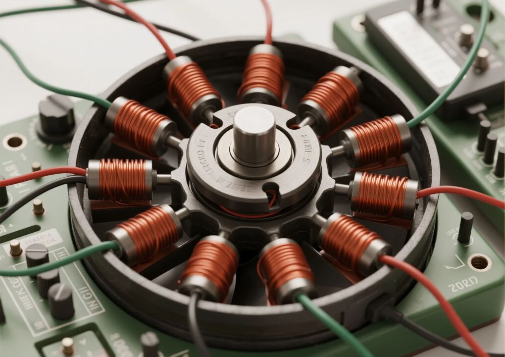
The Architectural Inversion vs. Brushed Motors
In a brushed DC motor, the windings sit on the spinning rotor and the magnets are fixed to the stator. Current reaches the rotor through carbon brushes pressing on a commutator. A BLDC inverts this: magnets on the rotor, windings on the stationary stator. That single inversion eliminates the only major wear path (the brush/commutator interface) and moves heat generation to the stator, where a housing or fan can dissipate it directly. The sparking and carbon dust of brushed commutation simply do not occur.
BLDC vs. PMSM — Same Machine, Different Winding
Engineers often ask whether a BLDC differs from a permanent-magnet synchronous motor (PMSM). Electromagnetically they are the same machine. The distinction is the back-EMF shape set by the winding and magnet design: a trapezoidal back-EMF is called BLDC (driven by six-step commutation), while a sinusoidal back-EMF is called a PMSM (driven by sinusoidal commutation or field-oriented control). In practice the terms overlap, and many “BLDC” drives now run sinusoidal/FOC firmware. For the working principle below, the difference is in the control waveform, not the physics.
How a BLDC Motor Works — Step by Step
The operating principle reduces to the Lorentz force law: a current-carrying conductor in a magnetic field experiences a force. A BLDC motor applies this force in a carefully timed sequence so the net torque always points the same way. The sequence is the job of electronic commutation.
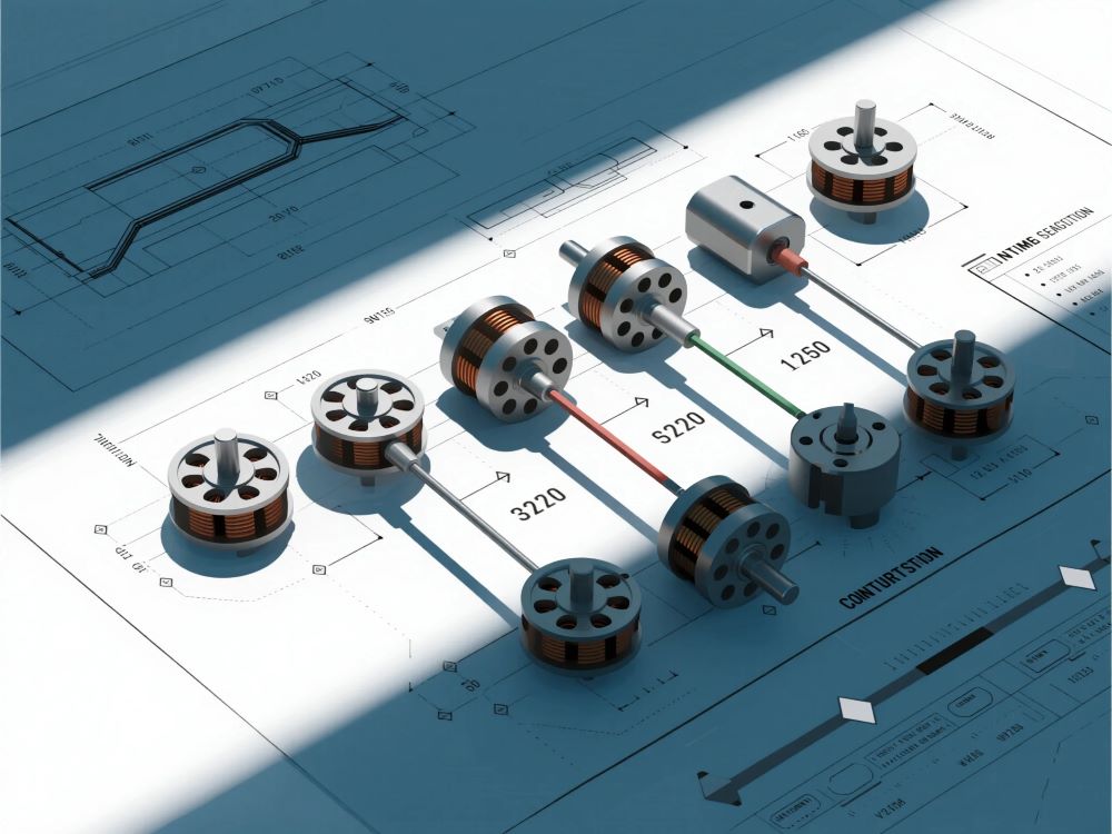
The Five-Stage Commutation Loop
- Power on. A DC supply (battery, rectified mains, or 24 V/48 V rail) feeds the controller, not the motor directly. A BLDC is never a two-wire device — see why a BLDC has three motor wires plus sensor lines.
- Position sense. The controller determines rotor angle from three Hall sensors, an encoder/resolver, or a sensorless back-EMF estimate.
- Energize. Power transistors (MOSFETs or IGBTs) in the inverter stage switch DC current through two of the three stator phases.
- Generate torque. The energized windings produce a magnetic field that attracts the opposite rotor poles and repels like poles, producing rotation.
- Advance. As the rotor turns, the sensor updates the angle; the controller commutates to the next phase pair, sustaining smooth, continuous torque.
Six-Step (Trapezoidal) Commutation Sequence
The most common drive method energizes two phases at a time and leaves one floating, stepping through six states per electrical revolution (120° conduction). The Hall sensor pattern selects the active pair:
| Step | Hall (A,B,C) | Phase A | Phase B | Phase C | Rotor sector |
|---|---|---|---|---|---|
| 1 | 1 0 1 | + | − | off | 0–60° |
| 2 | 1 0 0 | + | off | − | 60–120° |
| 3 | 1 1 0 | off | + | − | 120–180° |
| 4 | 0 1 0 | − | + | off | 180–240° |
| 5 | 0 1 1 | − | off | + | 240–300° |
| 6 | 0 0 1 | off | − | + | 300–360° |
Each 60° step snaps the stator field to the next position, pulling the rotor forward. The discrete steps cause torque ripple — the main reason high-end drives add sinusoidal or FOC commutation. Pulse-width modulation (PWM) on the active phases sets the average voltage and therefore the speed; see the motor controller guide for the drive stage.
The Rotating Magnetic Field and Lorentz Force
Commutation frequency sets the field’s rotational speed; the rotor follows because the permanent magnets are locked to the nearest field position. Speed is therefore controlled by commutation rate, not by supply voltage alone — a key difference from a brushed motor, where speed is set largely by voltage and load. The net electromagnetic torque is T = Kt × Iq, where Kt is the torque constant and Iq the torque-producing (quadrature) current. We return to Kt in the engineering-data section because it is the single most useful number on a BLDC datasheet.
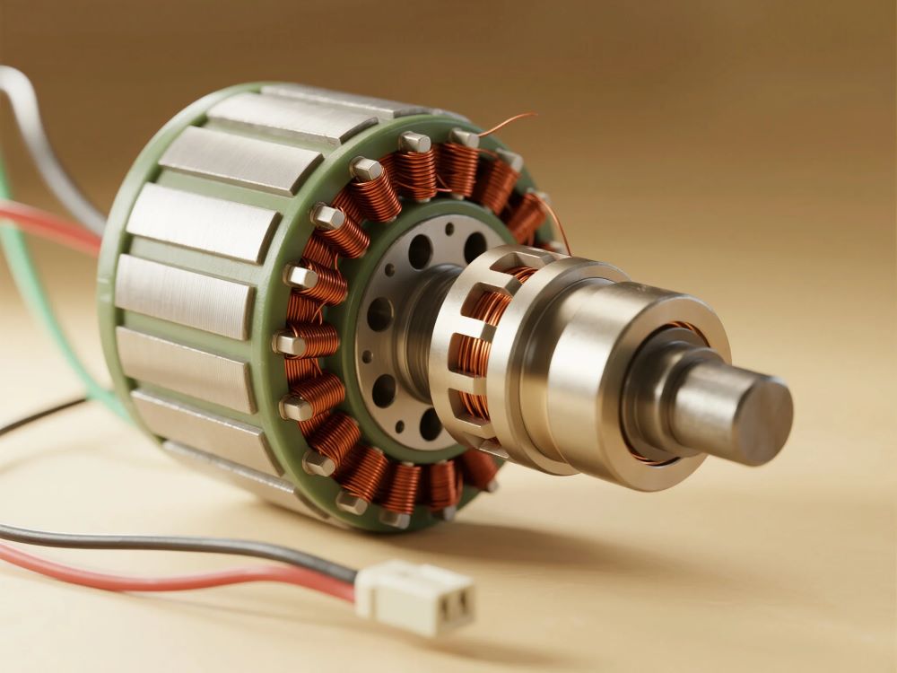
Inside the Three Core Components
A BLDC system is three parts: a stator, a magnet rotor, and an electronic controller. Each is engineered as a unit.
Stator — Laminated Steel and Three-Phase Windings
The stator is a stack of electrical-steel laminations with slots holding three-phase windings (U/V/W, 120° apart). Lamination limits eddy-current loss; the winding layout sets voltage constant, resistance, inductance, and thermal behavior. Because the windings are stationary, heat flows straight to the housing — a decisive cooling advantage over a brushed rotor. Coil count, slot fill, and turn count are what determine the motor’s Ke and Kt values.
Rotor — Permanent Magnets and Pole Count
The rotor carries sintered NdFeB (neodymium) or SmCo magnets, alternating north/south. Pole count is a design lever: more poles raise torque per amp and lower the base speed; fewer poles raise top speed. Pole count also sets the electrical frequency for a given mechanical speed, which constrains the controller (see the data section). Air gap, magnet grade, and rotor inertia set torque density, max speed, and cogging.
Electronic Controller — Inverter, Gate Drivers, Sensors
The controller is not optional. It contains a microcontroller (commutation + control law), gate drivers, and power transistors that switch the phases; current and position feedback close the loop; protection circuits handle over-current, over-voltage, and over-temperature. Higher-performance drives implement field-oriented control; simpler ones do six-step. For pre-integrated options, see our BLDC controller packages and the five types of control motors comparison.
BLDC vs. Brushed DC Motor — Feature Comparison
This is the comparison buyers actually run. The architectural inversion cascades into efficiency, life, and cost differences across the product lifecycle. (For the dedicated deep-dive, see our brushless vs. brushed difference page and the limitations of brushless motors.)
| Attribute | Brushless DC (BLDC) | Brushed DC |
|---|---|---|
| Commutation | Electronic (controller + sensors) | Mechanical (brushes + commutator) |
| Typical efficiency | 85–95% | 70–85% |
| Service life | 10,000–30,000+ h (bearings only) | 1,000–5,000 h (brush wear) |
| Maintenance | Minimal — bearing lube | Regular brush replacement |
| Heat location | Stator (easy to cool) | Rotor (hard to cool) |
| EMI / sparking | Very low | Brush arcing, significant EMI |
| Speed range | Up to 100,000+ rpm | Limited by brush contact (~8,000 rpm) |
| Low-speed torque | Strong, consistent from zero | Drops as brushes wear |
| Hazardous environments | Suitable (no arc) | Unsafe (ignition risk) |
| Controller required | Yes (ESC / driver IC) | No (direct DC) |
| Upfront cost | Higher (motor + drive) | Lower |
The efficiency gap widens under partial load: a brushed motor loses more at low speed, while a BLDC holds 85–95% across the range. Total cost of ownership therefore favors brushless once annual running hours exceed roughly 2,000–3,000, with payback commonly cited at 12–24 months through saved energy and avoided brush downtime.
Engineering Data: Efficiency, Temperature, and the Kt/Ke Relationship
Efficiency Ranges and Where the Losses Go
A well-designed BLDC reaches 85–95%. Losses split into copper (I²R in windings), iron (hysteresis + eddy current in laminations), mechanical (bearings, windage), and stray/electronic (switching). Because the copper loss is on the stator, the dominant heat source sits where a heatsink or fan can remove it — unlike a brushed motor, whose rotor copper loss is buried inside the spinning assembly. Efficiency class language follows IEC 60034-1 and is summarized in our motor efficiency class guide.
Temperature and Insulation Limits
| Limit | Typical value | Notes |
|---|---|---|
| Winding insulation class (IEC 60034-1) | Class B 130°C / F 155°C / H 180°C | NEMA MG 1 aligns; class sets max winding temp |
| Bearing / grease ceiling | 80–120°C | Grease softens above ~85°C; re-lube or sealed bearings |
| Magnet (NdFeB) max | ~80–150°C (grade-dependent) | Above Curie onset, permanent flux degrades |
| Controller semiconductor junction | ≤150°C (MOSFET/IGBT) | Thermal pad to housing; derate in enclosed builds |
Continuous S1 duty must be sized to the thermal ceiling, not just the torque rating. IEC 60034-1 defines S1 (continuous), S2 (short-time), and S3 (intermittent) duty; a motor rated S1 can run indefinitely, while an S2/S3 unit overheats if forced into continuous service. Apply a 1.5–2× service factor on torque for shock loads.
The Back-EMF and Torque Constants (Kt and Ke)
Two numbers dominate BLDC math, and most marketing pages omit or confuse them:
- Torque constant:
Kt = T / Iq(N·m per amp). - Back-EMF constant:
Ke = E / ω(volts per rad/s), whereEis the generated back-EMF andωthe mechanical speed in rad/s. - SI relationship:
Kt = Kenumerically when both use SI units (N·m/A and V·s/rad). A motor withKe = 0.04 V/(rad/s)also hasKt = 0.04 N·m/A. - Speed–voltage:
E = Ke × ω— the back-EMF rises with speed and opposes the supply, setting the top speed for a given bus voltage.
This identity is why a higher-Kt motor (more torque per amp) also has a higher Ke (more back-EMF per rpm): it reaches its voltage limit at a lower speed. You cannot have both high torque density and high top speed in the same winding without more voltage or more poles.
Pole Count and Electrical Frequency Trade-off
The stator field must switch at the electrical frequency fe = p × n / 120, where p is pole count and n mechanical rpm. More poles raise torque per amp but demand a higher electrical frequency at a given speed — raising iron and controller switching loss and capping top speed for a fixed drive bandwidth.
| Poles (p) | fe at 3,000 rpm | fe at 6,000 rpm | Torque/amp | Trade-off |
|---|---|---|---|---|
| 2 | 50 Hz | 100 Hz | Low | Highest speed, lowest torque density |
| 4 | 100 Hz | 200 Hz | Medium | Balanced; most common |
| 8 | 200 Hz | 400 Hz | High | More torque/amp, more iron + switching loss |
| 12+ | 300 Hz+ | 600 Hz+ | Very high | Low-speed direct-drive; needs wide-bandwidth drive |
Counterintuitive insight — “more poles = more torque” is half true: adding poles does raise torque per amp, but it also raises the electrical frequency for the same rpm, pushing iron and switching losses up and lowering the achievable top speed on a given controller. A spec sheet that wins on “torque” via many poles may quietly cap your maximum rpm. Pole count is a system choice, not a free upgrade.
Inrunner vs. Outrunner, Sensored vs. Sensorless
Two orthogonal axes define a BLDC’s mechanical and control personality.
| Axis | Option A | Option B | When to choose |
|---|---|---|---|
| Rotor layout | Inrunner (rotor inside stator) | Outrunner (rotor wraps stator) | Inrunner for high rpm / gear-coupled; outrunner for direct-drive low-speed torque |
| Feedback | Sensored (Hall/encoder) | Sensorless (back-EMF estimate) | Sensored for loaded starts & low speed; sensorless for fans, pumps, sealed units |
Inrunner vs. Outrunner
An inrunner concentrates magnet mass near the axis, giving low inertia and fast acceleration at 5,000–50,000 rpm — power tools, spindles, medical devices. An outrunner places magnets at maximum radius, producing high torque at low rpm without a gear stage — drone props, e-bike hubs, fans, direct-drive washers. Outrunners run smoother at low speed but shed heat mainly through the housing.
Sensored vs. Sensorless
Sensored BLDC embeds three Hall sensors 120° apart, giving reliable torque from zero rpm — essential for servo joints, robotic arms, and EV traction. Sensorless estimates position from back-EMF, which is proportional to speed and zero at standstill; below roughly 10–15% of max rpm the signal is too weak, so sensorless needs an open-loop startup ramp and is unsuitable for controlled starts under full load. The payoff is lower cost, fewer wires, and no Hall leads to corrode — ideal for HVAC blowers and pump drives.
Commutation Methods: Six-Step, Sinusoidal, and FOC
| Method | Current shape | Torque ripple | Complexity | Best for |
|---|---|---|---|---|
| Six-step (trapezoidal) | Rectangular, 120° blocks | Moderate | Low | Cost-sensitive drives, power tools, pumps |
| Sinusoidal | Sine waves | Low | Medium | Quiet fans, medical, audio-sensitive gear |
| Field-oriented control (FOC) | Decoupled Id/Iq in rotating frame | Very low | High | Servos, EVs, robotics, precise torque |
FOC (vector control) regulates the current in two perpendicular axes — Id (flux) and Iq (torque) — to maximize torque per amp across the whole speed range and deliver near-silent operation. It is the standard for high-speed robotic and automation drives and EV traction. The cost is the control algorithm and higher-resolution feedback.
Best Applications for BLDC Motors
Where Brushless Is Mandatory
- Explosive or cleanroom environments — no brush arc, no carbon particulate. Brushed motors are simply unsafe here.
- Continuous or high-duty cycles — 10,000–30,000 h life versus 1,000–5,000 h for brushes.
- Precision motion — closed-loop speed/torque/position for servo and automation systems.
- Battery-powered devices — higher efficiency extends runtime per charge.
Where Brushed Still Wins
Brushed motors remain rational for cost-constrained, intermittent-duty products (window regulators, wipers, toys), where brush wear is irrelevant over the product life, and for series-wound traction needing maximum stall torque at zero speed. See why power tools still use brushed motors for the nuance. The point is fit-for-purpose, not “brushless is always better.”
How to Select a BLDC Motor
Selection Checklist
- Define output: required torque
Tand speedn, duty (S1/S2/S3), ambient, life target. - Pick topology: inrunner vs. outrunner; sensored vs. sensorless; pole count for the speed range.
- Size the torque current:
Iq = T / Kt; confirm the controller and winding handle it. - Check the voltage budget:
Vbus ≥ Ke×ω + Iq×Reff + switch drops(worked below). - Verify thermal: continuous duty needs thermal headroom; intermittent is more forgiving.
- Confirm feedback: Hall/encoder if you start under load; sensorless only if speed stays above the back-EMF threshold.
- Specify envelope & load: shaft, flange, radial/axial limits — see motor flange reference.
- Request documented data: efficiency map, Kt/Ke, L10 life — not marketing claims.
Worked Example — Sizing a 24 V Cooling-Fan BLDC
Requirement: a forced-convection fan needs T = 0.18 N·m at n = 2,800 rpm, continuous S1 duty, on a 24 V supply. Chosen 4-pole motor: Kt = Ke = 0.038 (N·m/A and V·(rad/s)−1), phase resistance R = 1.2 Ω, line-to-line effective 2R = 2.4 Ω.
| Step | Calculation | Result |
|---|---|---|
| Mechanical speed | ω = 2π × 2800 / 60 | 293.2 rad/s |
| Required torque current | Iq = 0.18 / 0.038 | 4.74 A |
| Back-EMF at speed | E = 0.038 × 293.2 | 11.14 V |
| Resistive drop (2 phases) | Iq × 2R = 4.74 × 2.4 | 11.4 V |
| Switch + margin | est. 1.5 V | 1.5 V |
| Required bus voltage | 11.14 + 11.4 + 1.5 | 24.0 V |
The math says a 24 V rail is exactly enough — with zero headroom. That is the trap. Copper resistance rises about 0.4% per °C; at a 40°C winding rise, R becomes ~1.32 Ω (effective 2.64 Ω), the drop climbs to ~12.5 V, and the required bus hits ~25 V — above the 24 V supply. The motor then cannot hold 0.18 N·m at 2,800 rpm as it warms; speed droops or current rises. The fixes are all real engineering levers: choose a lower-Kt winding (less back-EMF), raise the bus to 36 V, or add a gear stage to cut required torque. Raising voltage is usually cheapest. This is why Kt/Ke and bus voltage must be co-sized — the detail spec sheets omit.
Common Engineering Mistakes
- Treating a BLDC like a brushed motor. Connecting it straight to DC will not spin it; it needs a controller. (See the three-wire hookup.)
- Sizing to nameplate torque at 24 V with no headroom. Thermal resistance rise pushes the required bus above the rail, as the example shows.
- Choosing sensorless for a loaded standstill start. Back-EMF is zero at rest; the motor needs an open-loop ramp and cannot hold full load from zero.
- Chasing pole count for torque. More poles raise torque/amp but also electrical frequency and losses, capping top speed.
- Ignoring the controller as part of the motor. Efficiency, EMI, and torque ripple are set as much by the drive as the windings.
- Overlooking magnet temperature. NdFeB loses flux above its grade limit; hot environments need SmCo or derating.
- No stall/over-current protection. A stalled BLDC draws many times rated current and cooks the inverter.
- Confusing continuous vs. peak torque. Peak is brief; S1 duty must use the continuous rating.
Troubleshooting BLDC Motors
| Problem | Likely Cause | Solution |
|---|---|---|
| Won’t start / stutters | Hall miswire; bad phase; sensorless ramp too short | Verify Hall sequence; check phase order; lengthen open-loop ramp |
| Low speed / weak torque | Bus voltage below Ke×ω+drop; under-sized Kt | Raise bus or pick lower-Kt winding; re-run sizing math |
| Overheating | Overload; high ambient; poor housing cooling | Derate; improve heatsink; verify duty vs. S1 rating |
| Excess audible noise / vibration | Six-step torque ripple; unbalanced rotor | Move to sinusoidal/FOC; balance rotor; check bearings |
| Erratic control / EMI | Unshielded sensor leads; no snubbers | Shield Hall wires; add filtering; comply with CISPR 11 |
| Cogging at low speed | Slot/pole interaction; open-loop sensorless | Use sensored FOC; skew magnets or slots |
| Controller fault / shut-down | Over-current or over-temp trip | Set current limit; check thermal pad; reduce load |
Why Choose Greensky Power?
Greensky Power is a China-based custom electric motor manufacturer serving medical, robotics, automotive, and industrial OEMs in 50+ countries. Our high-efficiency BLDC motors — including 12 V BLDC and 24 V BLDC gear motors — are built to IEC 60034, NEMA MG 1, and DOE 10 CFR Part 431, with ISO 9001, CE, and efficiency certifications. We supply custom BLDC solutions (IP67/IP69K sealing, special voltages, proprietary control) and OEM/ODM integration with pre-configured motor-controller packages tested to CISPR 11 Class A. Our applications engineers size from your output torque, speed, and duty requirement — including the Kt/Ke and bus-voltage math above — rather than generic claims, and provide BLDC technical support across North America and Europe.
Related Resources
- BLDC motor product overview (pillar page)
- BLDC motor basics
- Brushless vs. brushed DC motors — key differences
- Limitations of brushless DC motors
- Why a BLDC has three wires
- Motor controller and drive guide
- How to calculate motor torque
- What is a DC motor?
- AC vs. DC motors
- Why brushed motors spark
- What are motor brushes?
- Why power tools use brushed motors
- Servo vs. stepper motor
- Motor efficiency classes
- Motor flange dimensions
- High-efficiency BLDC motors
- 24 V BLDC gear motors (wholesale)
- Custom BLDC for your application
- High-speed BLDC for robotics
- Five types of control motors
- OEM/ODM customization
- DC motors category
References
- IEC 60034-1:2022 — Rotating electrical machines, general requirements (insulation & temperature classes). webstore.iec.ch/en/publication/65446
- IEC 60034-30-1 — Efficiency classes of line-operated AC motors. webstore.iec.ch/publication/91195
- ANSI/NEMA MG 1-2021 — Motors and Generators standard. webstore.ansi.org/standards/nema/ansinemamg2021
- NEMA — Motor and Generator product resources. nema.org/products/pages/motor-and-generator.aspx
- U.S. DOE — Motor load and efficiency reference (10 CFR Part 431 context). energy.gov/sites/prod/files/2014/04/f15/10097517.pdf
- IEA — Electric motors and energy efficiency. iea.org/energy-system/industry/electric-motors
- SKF — Bearing failures and their causes. skf.com/group/support/bearing-failures-and-their-causes
- Siemens — SIMOTICS electric motors. siemens.com/global/en/products/drives/electric-motors.html
- IEEE Xplore — Peer-reviewed micro-motor / BLDC design paper. ieeexplore.ieee.org/document/6342334
- maxon — EC (electronically commutated) motor technology. maxongroup.com/maxon/view/content/ec-technology
- FAULHABER — Brushless DC motor know-how. faulhaber.com/en/know-how
- Yaskawa — Motion and motor technical downloads. yaskawa.com/downloads/search-index
- AGMA — Gear and drive rating standards. agma.org
- Tsubaki — Gear motor selection technical data (service factors). en.tt-net.tsubakimoto.co.jp/tecs/engd/gen/engd_gen_ggm_sry.asp
Technical content reviewed by Greensky Power applications engineering. Figures are typical industry ranges; final specification requires verification against the selected motor, controller, and duty cycle. Standards links reflect the publisher’s current public URLs and should be re-verified before publication.
FAQ
How does a brushless DC motor actually work?
A BLDC motor spins by electronically switching current through three stationary stator windings in sequence, creating a rotating magnetic field that pulls a permanent-magnet rotor along. A controller reads rotor position (Hall sensors or back-EMF) and commutates at the right moment—replacing the brushes and commutator of a brushed motor with semiconductors.
Is a BLDC motor the same as a permanent-magnet synchronous motor?
Electromagnetically yes—they are the same machine. The label differs by back-EMF shape: trapezoidal back-EMF driven by six-step commutation is called BLDC; sinusoidal back-EMF driven by sinusoidal/FOC control is called PMSM. Many BLDC drives run sinusoidal firmware.
Why does a BLDC need a controller and not just a battery?
Without brushes there is no mechanical commutation, so an electronic controller must decide which windings to energize based on rotor position. Connecting a BLDC directly to DC will not spin it. The controller also sets speed via PWM and protects the power stage.
What is the difference between sensored and sensorless BLDC?
Sensored motors use Hall sensors or encoders for reliable torque from zero rpm—ideal for servos and loaded starts. Sensorless motors estimate position from back-EMF, which is zero at standstill, so they need an open-loop startup ramp and suit fans, pumps, and sealed units running above a minimum speed.
How efficient are brushless DC motors compared with brushed?
BLDC motors typically reach 85–95% efficiency across the speed range, versus 70–85% for brushed. Because heat is generated in the stator (easy to cool) rather than the rotor, BLDC also sustains efficiency better under partial load, with total-cost-of-ownership payback often within 12–24 months.
What do Kt and Ke mean on a BLDC datasheet?
Kt is torque per amp (N·m/A); Ke is back-EMF per rad/s (V·s/rad). In SI units they are numerically equal. A higher Kt gives more torque per amp but also a higher Ke, so the motor hits its voltage limit at a lower speed—why torque density and top speed must be co-sized with the supply voltage.
