
Planetary Gearmotors for Solar Tracker
Quick Answer: A planetary gearmotor is the drive of choice for modern single- and dual-axis solar trackers because it delivers the combination tracking demands: high torque density, low backlash (1–3 arcmin), and high efficiency (97–99% per stage), in a compact coaxial package that survives years outdoors. Solar tracking is a slow, torque-heavy, weather-exposed duty — trackers rotate a few degrees every few minutes but must hold position against wind gusts, at ±0.1° accuracy, in −40 °C to 60 °C. The result is a 15–35% gain in energy yield over fixed-tilt systems, delivered by a gearmotor specified for IP65/IP67 sealing, high holding torque and a brake (since planetary stages are not self-locking).
Contents
- What Is a Planetary Gearmotor for Solar Trackers?
- How a Solar Tracker Drive Works
- Single-Axis vs Dual-Axis Trackers
- Planetary vs Worm vs Helical
- Engineering Data: Torque, Ratio, Accuracy
- Worked Example: Sizing for Wind Torque
- Best Applications
- How to Select a Tracker Gearmotor
- Common Engineering Mistakes
- Troubleshooting
- FAQ
- Why Choose Greensky Power?
What Is a Planetary Gearmotor for Solar Trackers?
A planetary gearmotor for a solar tracker is a DC motor (or BLDC) integrated with a planetary gearbox to rotate a photovoltaic array slowly and precisely toward the sun. Unlike a general industrial gearmotor, the tracker version is engineered for the field: sealed against dust and water, greased for a wide temperature range, and sized for high holding torque at near-zero speed rather than for continuous motion.
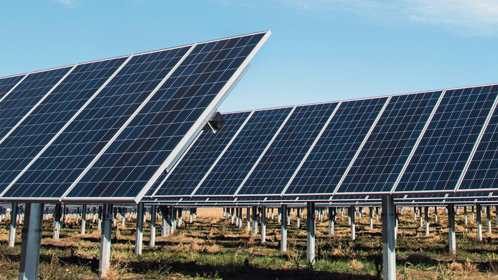
Solar tracking adds 15–35% more energy yield over fixed-tilt mounting, but that gain depends entirely on the drive rotating accurately for 20–25 years in unattended outdoor service. The gearmotor is therefore the highest-stakes single component in the system.
PMDC vs BLDC Drive Motor
Drive-motor choice follows the site and the duty. A permanent-magnet brushed DC (PMDC) motor is simple, inexpensive and easy to control, and its wide speed range helps with stow moves — but its brushes wear, so it suits intermittent single-axis duty. A brushless DC (BLDC) motor lasts far longer, runs quieter and more efficiently, and is the better fit for dual-axis or continuous-tracking systems and for large fleets where a single service call is costly.
Why Solar Duty Is Different
A tracker drive looks like any other gearmotor on paper, but its duty profile is unusual in four ways. First, it is intermittent — the array moves a few degrees every several minutes, then holds still. Second, it is torque-dominated — the load is the wind pushing on a large sail of panels, not a fast-moving inertia. Third, it is outdoor and unattended — desert heat, coastal salt and dust, with service calls measured in years. Fourth, it is accuracy-sensitive — a fraction of a degree of drift, repeated thousands of times, quietly erodes annual yield. These four facts, not the motor’s nameplate, are what a proper specification starts from.
How a Solar Tracker Drive Works
At the mechanical heart of every tracker is one actuator whose only job is to turn electrical energy into a few precise degrees of motion, on demand, for decades. Understanding that actuator — a motor whose speed is traded away for torque through a deep reduction — is the whole subject in miniature. The conversion happens in three clear steps:
- The motor spins fast. A 12 V or 24 V DC motor runs at thousands of rpm with modest torque, drawing little power from the off-grid PV-plus-battery supply.
- The planetary stage reduces speed and multiplies torque. A single stage reduces 3–10:1; stacked stages (or a slew-drive arrangement) reach 500:1 to 10,000:1, turning thousands of rpm into a few rpm at the output with very high torque.
- A brake (or worm stage) holds position. Because planetary gears are not self-locking, the drive uses an electrical brake or a worm slew stage so wind gusts cannot back-drive the array when the motor is idle.
An optional encoder closes the loop, feeding shaft position back to the astronomical tracking algorithm for sub-degree pointing and safe “return-to-stow” before storms.
Why Trackers Move So Slowly
Compared to a conveyor or a robot axis, a solar tracker is nearly stationary. A single-axis row may turn only ~180° over a full day — a fraction of a degree per minute. The drive’s job is therefore not speed but holding torque and resolution: it must creep through a large reduction (500:1 to 10,000:1) so that a fast, efficient motor produces a slow, powerful, finely-controlled output. Understanding this inversion — speed is the enemy, torque and resolution are the point — is the key to every selection decision that follows.
Put another way, the tracker drive is judged not by how fast it moves but by how reliably it does not move when it should not, and how precisely it moves when it should. That single criterion explains nearly every requirement in this guide: the deep ratio, the low backlash, the brake, the sealing and the wide-temperature grease all exist to make a small motion repeat correctly for a quarter of a century.
Single-Axis vs Dual-Axis Trackers
| Attribute | Single-axis | Dual-axis |
|---|---|---|
| Motion | East–west (horizontal or tilted) | Azimuth + elevation |
| Yield gain | ~15–25% | ~25–35% |
| Typical drive | Slew drive (worm) or planetary | Planetary / high-precision |
| Accuracy demand | Moderate | ±0.1° (CPV needs precision) |
| Cost / complexity | Lower, utility-scale | Higher, CPV & heliostats |
Single-axis trackers dominate utility-scale farms and can use worm slew drives for self-locking; dual-axis and concentrating (CPV) systems lean on precision planetary stages for the tighter pointing accuracy.
Planetary vs Worm vs Helical
| Attribute | Planetary | Worm (slew) | Helical |
|---|---|---|---|
| Efficiency | 97–99% / stage | 50–90% | 85–96% |
| Backlash / accuracy | 1–3 arcmin | Higher | Low–medium |
| Self-locking | No (needs brake) | Yes | No |
| Torque density | Very high | Medium–high | Medium |
| Best for | Dual-axis, CPV, precision | Single-axis slew, self-locking | High-efficiency general |
The choice is a real engineering trade-off, not a default. Worm slew drives self-lock but lose efficiency; planetary stages are far more efficient and precise but need a brake. See planetary vs worm gear motor for the full comparison.
Engineering Data: Torque, Ratio, Accuracy
Key Specifications at a Glance
| Parameter | Typical tracker value |
|---|---|
| Output speed | A few rpm (creep) |
| Reduction ratio | 500:1–10,000:1 (slew drive) |
| Backlash | 1–3 arcmin |
| Tracking accuracy | ±0.1° (closed-loop) |
| Efficiency | 97–99% / stage |
| Ambient temperature | −40 °C to 60 °C |
| Ingress protection | IP65–IP67 |
| Supply | 12 V / 24 V DC (off-grid) |
Torque and Ratio
Output torque follows the usual gear law: Tout = Tmotor × i × η. Solar trackers need enormous holding torque at near-zero speed, so ratios are large — a slew-drive arrangement runs 500:1 to 10,000:1. Size the torque with a 1.5–2× safety factor over the calculated peak wind-load torque, because a gust must not stall or back-drive the array.
Accuracy and Backlash
Tracking accuracy is set by backlash: precision tracker planetary stages hold 1–3 arcmin (sub-arcminute on the best units), enabling pointing within ±0.1° with a closed-loop encoder. Even a small angular error, repeated across thousands of cycles, measurably reduces annual yield.
Efficiency and Energy Budget
The tracker’s motor draws from the very system it serves, so efficiency is net power. Planetary stages run 97–99% single-stage and >90% multi-stage, versus 70–85% for cycloidal and 50–90% for worm — a difference that directly improves net PV output over a 25-year life. See motor efficiency classes for context.
Environment: IP, Temperature, Corrosion
- Sealing: IP65 minimum; IP66/IP67 preferred for coastal or high-humidity sites.
- Temperature: −40 °C to 60 °C ambient, with grease rated to ~120 °C.
- Corrosion: anodized or coated aluminum housing, stainless hardware for salt spray.
Sealing and Lubrication in Detail
Outdoor survival is mostly a sealing and lubrication problem. Tracker-specific planetary units use dual-lip oil seals, dust rings and labyrinth seals to keep sand, water and dust out while holding lubricant in, and they are factory-filled with long-life grease rated from −40 °C to 120 °C so the mesh neither hardens in winter nor breaks down in desert heat. The housing is die-cast aluminum, anodized or coated for corrosion and UV resistance. Together these details are what let a tracker run 20–25 years without a re-grease — and why a generic indoor gearmotor, no matter how strong, fails early in the field.
Self-Locking vs Braking
This is the decision that catches newcomers out. A worm gear is naturally self-locking — the worm cannot be back-driven by the wheel, so the array holds position with no power and no brake. A planetary gear is not self-locking, so it back-drives under wind unless you add an electrical brake or a separate holding mechanism. The trade-off is efficiency: worm stages lose energy to sliding friction (50–90% efficient), while planetary stages stay in the high 90s. The right answer depends on your site’s wind regime, your power budget and whether self-locking is worth the efficiency penalty.
Worked Example: Sizing for Wind Torque
A single-axis tracker row must hold and rotate against a peak wind load that produces 1,800 N·m of torque at the slew axis. The designer applies a 1.5× safety factor, so the design torque is 2,700 N·m. The candidate drive is a 24 V DC motor with 3 N·m rated torque through a 90%-efficient planetary stage.
- Derive the ratio from torque.
i = Tdesign / (Tmotor × η) = 2,700 / (3 × 0.9) = 1,000:1. - Check output speed. A 3,000 rpm motor through 1,000:1 gives 3 rpm — ideal for tracking (a few degrees per minute), confirming the ratio is practical, not just torque-driven.
- Add the holding brake. Because the planetary stage is not self-locking, an electrical brake (or a worm slew stage) holds the array against wind when the motor is off.
- Verify the environment. Specify IP65–IP67 sealing, −40 °C–60 °C grease and a corrosion-resistant housing for the site.
Counter-intuitive insight: a solar tracker is the inverse of most motion systems — it needs near-zero speed and enormous holding torque, so the gear ratio (1,000:1) is chosen to survive a wind gust, not to hit a cycle time. Engineers who size a tracker drive like a conveyor (starting from speed) routinely under-build the holding torque and pay for it in tracking drift and field failures.
Best Applications for Planetary Tracker Gearmotors
Where a planetary tracker gearmotor is the right call depends on how tightly the system must point and how much the site penalizes energy loss. Single-axis utility farms value holding torque and low maintenance; dual-axis and concentrating systems value backlash and accuracy; off-grid installations value efficiency above all. The applications below map each priority to the drive that serves it best.
- Dual-axis trackers — azimuth + elevation, where precision planetary backlash keeps pointing tight.
- Concentrating PV (CPV) and heliostats — the strictest ±0.1° pointing, served by low-backlash stages.
- Single-axis utility farms — planetary drives (with brake) or worm slew drives, depending on the self-locking vs efficiency trade-off.
- Off-grid / battery installations — high planetary efficiency maximizes net output where every watt-hour counts.
Drive Choice by Tracker Type
| Tracker type | Preferred drive | Reason |
|---|---|---|
| Single-axis (utility) | Worm slew drive or planetary + brake | Self-locking vs efficiency trade-off |
| Dual-axis | Precision planetary | Low backlash, two-axis accuracy |
| CPV / heliostat | High-precision planetary + encoder | Strict ±0.1° pointing |
| Off-grid / battery | High-efficiency planetary | Minimize self-consumption |
How to Select a Tracker Gearmotor
Selection is a sequence of six decisions that cascade from the site and the array, not from a catalog. Start from the wind load and required accuracy, derive the ratio and torque, then resolve the self-locking-versus-efficiency question and the environmental sealing. Done in this order, each step narrows the shortlist until only a handful of correctly-rated drives remain — which is the point, because a tracker drive bought wrong is multiplied across an entire farm.
- Compute peak wind torque at the slew axis and apply a 1.5–2× safety factor.
- Derive the ratio from torque and confirm the resulting output speed (a few rpm) is right for tracking.
- Choose the gearbox type — planetary for efficiency and precision, worm slew for self-locking.
- Decide on holding — electrical brake for planetary, or rely on a worm stage’s self-locking.
- Specify the environment — IP rating, temperature grease and corrosion-resistant housing.
- Confirm voltage and control — 12 V / 24 V DC, and encoder if closed-loop tracking is required.
Encoder or Open-Loop?
Basic timer-based trackers can run open-loop, but open-loop timing drifts over years of thermal cycles and mechanical wear. For utility farms and dual-axis or CPV systems, an encoder-equipped planetary gearmotor is the standard: it reports shaft position, speed and direction to the controller, enabling accurate return-to-stow ahead of storms, correction for mechanical drift, and predictive-maintenance diagnostics across a fleet of hundreds of trackers. The marginal cost of the encoder is repaid many times over in recovered yield and avoided field service.
Common Engineering Mistakes
- Sizing from speed, not wind torque. Undersized holding torque leads to drift and back-driving in gusts.
- Forgetting the brake. A planetary drive without a brake or worm stage will be back-driven by wind.
- Under-speccing the IP rating. IP55 fails in coastal or desert sites; IP65–IP67 is the norm.
- Ignoring grease temperature range. Standard grease hardens at −40 °C and starves the mesh.
- No safety factor. Sizing to nominal wind torque leaves no margin for gusts and panel ice.
- Skipping the encoder. Open-loop timing drifts over years; closed-loop feedback preserves yield.
The recurring theme is that a tracker drive is bought for a 20–25-year life in the field, not for a test bench. Every mistake above is cheap to prevent at specification time and expensive to fix as a fleet-wide field recall. Run the wind-torque math, add the safety factor, and specify the sealing and the holding mechanism as carefully as the torque — those are the differences between a tracker that pays for itself and one that becomes an operations liability.
Troubleshooting — Problem, Cause, Solution
| Problem | Likely cause | Solution |
|---|---|---|
| Tracker drifts / loses position | Backlash or open-loop timing drift | Use low-backlash planetary; add encoder feedback |
| Array back-driven in wind | Missing brake on planetary drive | Add electrical brake or worm slew stage |
| Water ingress / corrosion | IP rating too low | Spec IP66/IP67 + coated housing (SKF) |
| Stiff or stuck in cold | Grease not low-temperature rated | Use wide-temperature grease (−40 °C+) |
| Excess self-consumption | Low-efficiency gear stage | Switch to planetary for higher efficiency |
| Premature gear wear | Undersized torque / no safety factor | Recompute with 1.5–2× wind-torque margin |
Why Choose Greensky Power?
Greensky Power designs and manufactures custom DC and BLDC gearmotors and complete OEM actuator assemblies, engineered as one matched motor-and-gearbox system for outdoor solar duty. For your tracker program we supply:
- Precision planetary and planetary gear motors with low backlash, IP65–IP67 sealing and wide-temperature grease.
- Brushed and brushless drive options with optional brake and encoder for closed-loop tracking.
- Engineering support for torque calculation and motor selection.
Because we build the motor, the gearbox and the sealing as one matched outdoor-rated system, we can size the wind-holding torque, backlash, IP rating and brake exactly to your tracker geometry — instead of adapting a catalog part and hoping it survives the first storm season.
Related Resources
- Gearbox overview (pillar page)
- Electric motor basics (pillar page)
- Precision planetary gearbox deep dive
- Planetary gear motor
- Planetary vs worm gear motor
- Worm gearbox selection guide
- Brushless DC motor (BLDC) basics
- DC motors category
References
- IEC 60034-1:2022 — Rotating electrical machines, general requirements. webstore.iec.ch/en/publication/65446
- IEC 60034-30-1 — Efficiency classes of line-operated AC motors. webstore.iec.ch/publication/91195
- ANSI/NEMA MG 1-2021 — Motors and Generators. webstore.ansi.org/standards/nema/ansinemamg2021
- NEMA — Motor and generator product guidance. nema.org/products/pages/motor-and-generator.aspx
- U.S. DOE — Motor systems efficiency and load guidance. energy.gov — 10097517.pdf
- IEA — Electric motors and industrial efficiency. iea.org/energy-system/industry/electric-motors
- SKF — Bearing failures and their causes. skf.com — bearing failures
- Siemens — SIMOTICS electric motors product range. siemens.com — electric motors
- IEEE Xplore — Peer-reviewed motor / actuator design paper. ieeexplore.ieee.org/document/6342334
- IEEE Transactions on Industry Applications — Zhou & Shen, “Rotor Notching for Electromagnetic Noise Reduction of Induction Motors”, DOI 10.1109/TIA.2017.2681969. doi.org/10.1109/TIA.2017.2681969
- maxon — EC technology and gearhead selection. maxongroup.com — ec-technology
- FAULHABER — Brushless DC motors and micro-drive know-how. faulhaber.com — brushless DC motors
- Yaskawa — Motion and servo system technical downloads. yaskawa.com/downloads/search-index
- Tsubaki — Gearmotor selection technical reference (service-factor method). tsubakimoto.co.jp — selection reference
Technical content reviewed by the Greensky Power engineering team. Torque, efficiency, backlash and temperature figures are representative; confirm the exact ratings for your tracker configuration and site conditions with the supplier.
Why use a planetary gearmotor for a solar tracker?
Planetary gearmotors combine high torque density, low backlash (1–3 arcmin) and high efficiency (97–99% per stage), giving the precise, repeatable low-speed rotation a tracker needs while minimizing the tracker’s own energy consumption.
What gear ratio does a solar tracker gearmotor need?
Trackers need very low output speed and very high holding torque, so ratios are high — typically 500:1 to 10,000:1 in slew drives. The ratio is driven by wind-load torque and sub-degree positioning, not cycle time.
How accurate must a solar tracker be?
Precision planetary stages hold backlash to 1–3 arcmin, enabling sun-tracking accuracy within about 0.1° with an encoder for closed-loop control. Small angular errors, repeated over thousands of cycles, reduce annual energy yield.
Do planetary gearmotors self-lock for solar trackers?
No — planetary gears are not self-locking, so a tracker using one needs an integrated brake or holding mechanism to resist wind back-driving. Worm-based slew drives are naturally self-locking but less efficient.
What IP rating does a solar tracker gearmotor need?
IP65 (dust-tight, water-jet resistant) is the minimum; IP66/IP67 is preferred for coastal or high-humidity sites. Look for corrosion-resistant housings and wide-temperature grease for −40 °C to 60 °C operation.
What voltage are solar tracker gearmotors?
Most tracker controllers run on 12 V or 24 V DC, often powered by a small PV panel and battery since trackers are frequently off-grid. Confirm the motor voltage matches the controller and battery system.
