
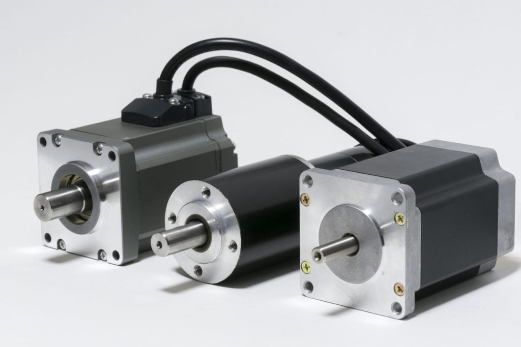
Servo Motor vs Stepper Motor: The Numbers That Actually Decide
Quick Answer
The choice is not about which motor is better; it is about which failure mode you can live with. A stepper fails by losing steps, silently, when the load exceeds the torque available at that speed. A servo fails by overheating when its RMS torque exceeds the continuous rating, usually without any position error at all. Both are sized with the same two numbers: the torque-speed point you actually need, and the inertia ratio you can tolerate. Above roughly 1,000 rpm, or wherever the load inertia exceeds about ten times the rotor, the stepper stops being an option. Below that, a closed-loop stepper often wins on cost.
- Two architectures, one question
- Why torque falls with speed, and what voltage has to do with it
- Reading a torque curve instead of a datasheet number
- The 0.005 degree problem: what stepper accuracy is
- Standstill: holding torque, current cutback and the servo
- Resonance, starting frequency and the acceleration limit
- Sizing both with one method: RMS torque
- System cost: where the three to five times comes from
- Closed-loop stepper: what it fixes, what it cannot
- Application matrix
- A six-point decision framework
- Why Greensky Power supplies both
- References
- FAQ
Two Architectures, One Question
Every positioning axis asks the same question: does the motor know where it is? A stepper answers no. It divides a revolution into fixed angular increments, typically 200 steps of 1.8 degrees, and the controller counts pulses to infer position. If the rotor falls behind the magnetic field, nothing reports it. A servo answers yes: an encoder closes the loop and the drive corrects the error every control cycle, tens of thousands of times per second.
That difference in feedback explains most of the practical differences, but not all of them. Two claims in the common comparison are wrong in opposite directions. A stepper is not simply a low-cost servo that loses steps, because its torque curve is shaped by the same inductance that limits any motor, and no amount of feedback restores the torque. And a servo is not automatically more accurate at the point of work, because encoder resolution is not the same thing as machine accuracy.
| Attribute | Stepper, open loop | Servo, closed loop |
|---|---|---|
| Position feedback | None; position is inferred from pulse count | Encoder, measured every control cycle |
| Error detection | None; a lost step is invisible | Continuous; following error is bounded by a limit |
| Rotor construction | High pole count, typically 50 rotor teeth giving 100 poles | Low pole count, commonly 4 to 8 poles |
| Motion character | Discrete increments; one settling oscillation per step | Continuous torque; smooth across the speed range |
| Drive complexity | Pulse generator plus chopper driver | Field-oriented control with current, velocity and position loops |
| Rated duty basis | Winding temperature at holding current | Continuous torque at a specified temperature rise |
| Typical failure mode | Silent step loss, then scrap or a crash | Overload or overheat fault, which is at least reported |
The terminology itself is standardised, and that matters when you compare quotations from two suppliers. NEMA ICS 16 defines the ratings, torque terms and feedback terms for both motor families, including separate definitions for servo and stepping motors and a definition of torsional resonance [9]. If a datasheet uses “holding torque” for a servo, or “rated torque” for a stepper without saying at what speed, it is not using the standard vocabulary.
Why Torque Falls With Speed
A stepper produces its highest torque at zero speed and progressively less as speed rises. The mechanism is inductance. Each phase is a coil with an electrical time constant, and current can only rise as fast as the supply voltage allows: the rate of change is the difference between supply voltage, resistive drop and back-EMF, divided by inductance. At low step rates there is ample time to reach rated current. At high step rates the next commutation arrives before the current has built up, so the effective current, and with it the torque, falls.
The supply voltage is not a detail, because it sets how fast the phase current can rise. Doubling the bus voltage roughly doubles the initial rate of current rise, and the same motor sold with a 24 V driver and with a 48 V driver therefore produces two very different torque curves. A catalogue curve drawn at one voltage tells you almost nothing about the other.
What this means for a comparison table
Most “stepper versus servo” tables compare a stepper’s holding torque with a servo’s continuous torque and conclude that the stepper is stronger. That comparison is invalid at any speed above zero, and it is the most common error in these comparisons. The correct comparison is at the speed and torque of the actual motion profile, on curves drawn at the same bus voltage.
| Speed | NEMA 23 stepper, about 1.5 N·m holding | 400 W servo, about 1.27 N·m continuous |
|---|---|---|
| 0 rpm | 1.5 N·m at rated current; less if current cutback is active | 1.27 N·m continuous, available as a holding torque |
| 300 rpm | Roughly 1.1 to 1.3 N·m on a 48 V driver, noticeably less on 24 V | 1.27 N·m continuous |
| 600 rpm | Around 0.7 to 1.0 N·m on 48 V; the curve is already bending | 1.27 N·m continuous |
| 1,500 rpm | Often 0.2 to 0.4 N·m; the region where step loss appears | 1.27 N·m continuous, plus a peak of about 3.8 N·m |
| 3,000 rpm | Usually below 0.1 N·m; not a usable operating point | 1.27 N·m continuous to rated speed |
Those stepper figures are ranges, not specifications, because they move with bus voltage, driver chopping frequency and motor inductance. A supplier who quotes a single number “at 1,500 rpm” without stating the driver voltage has given you a number you cannot use. The servo column is flat because a servo is a torque source up to its rated speed; beyond that it enters constant-power operation and torque falls as speed rises.
Reading a Torque Curve Instead of a Datasheet Number
Two curves decide the whole comparison, and both are published by every serious manufacturer. For the stepper, it is the pull-out curve: the maximum torque the motor can deliver at each speed without losing synchronisation [3]. For the servo, it is the continuous and peak torque against speed.
When you open those curves, three readings carry the decision:
- Where the stepper curve bends. The knee is set by inductance and supply voltage. Below the knee, torque is roughly flat; above it, the curve falls steeply. Your motion profile must sit below the knee with margin, not on the knee.
- How much of the servo curve is continuous. The peak region is a thermal allowance measured in seconds, not a second operating point. A drive that can deliver three times rated torque for two seconds cannot do it for twenty.
- Whether both curves were drawn at your bus voltage. A stepper curve at 48 V and a servo curve at 400 V are not comparable in the way the axis will actually run, but they are at least internally consistent. A stepper curve at 24 V compared with a servo at 400 V flatters the servo by a wide margin.
The 0.005 Degree Problem
Comparison articles routinely state that a stepper is accurate to plus or minus 0.005 degrees and a servo to plus or minus 0.02 degrees, and then explain why the servo is nevertheless better. The first number is wrong by roughly an order of magnitude, and the second is not a machine accuracy at all. Both errors matter, because they hide the real distinction.
Stepper accuracy is specified as stop position accuracy: the difference between where the rotor should stop and where it does stop, measured at no load. Oriental Motor puts this within plus or minus 3 arcminutes, which is plus or minus 0.05 degrees, under no load [2]. The same reference gives frame-dependent figures for angular transmission accuracy: 0.1 degrees at 28 and 42 mm frames, 0.09 degrees at 60 mm, and 0.07 degrees at 90 mm. A NEMA 23 sits in the 0.09 degree band.
| Metric | What it actually means | Typical value |
|---|---|---|
| Stepper stop position accuracy | Error at one stop, no load, non-cumulative | ±3 arcmin (±0.05°); 0.07 to 0.10° by frame |
| Stepper under load | Additional angular displacement from the angle-torque characteristic | Proportional to friction load; doubles over a round trip |
| Stepper after a lost step | Unbounded; nothing detects or corrects it | One lost step = 1.8° of permanent error |
| Servo encoder resolution | Smallest position the drive can distinguish | 17-bit = 131,072 counts/rev = 0.0027° |
| Servo axis accuracy | Encoder error, plus coupling, belt or gearbox lost motion | Often 0.02 to 0.1° at the load, not at the shaft |
At the shaft, a stepper is not dramatically less accurate than a servo: 0.09 degrees is a real number, and it does not accumulate step by step. The difference that matters is bounded versus unbounded error. A servo detects a disturbance and drives the error back within the following-error limit; a stepper accumulates whatever the load did to it and never reports the total.
Resolution is not accuracy
There is also a resolution illusion. A 17-bit encoder resolves 0.0027 degrees at the motor shaft, but a belt-driven axis with a 5:1 reduction and a compliant belt will not position a load to anything like that. Resolution is a property of the feedback device; accuracy is a property of the machine. Buyers who compare encoder bits and forget the mechanics are comparing the wrong two numbers.
Standstill: Holding Torque, Current Cutback and the Servo
The standstill behaviour of the two motors is where the folklore is thickest, and both common claims are wrong. The claim that a stepper always burns full current while holding ignores current cutback. The claim that a servo produces no torque at zero speed and therefore needs a brake is simply incorrect.
Most stepper drivers reduce motor current automatically when no pulses arrive, typically to about 50 percent of the setting, and to about 40 percent on some series, within roughly a tenth of a second [2]. Holding torque falls in proportion to the current actually flowing, which the manufacturer states as a simple ratio of standstill current to rated current [3]. So a 1.5 N·m motor with cutback enabled holds about 0.75 N·m and gets noticeably cooler. Turning cutback off restores the holding torque and restores the heat.
A servo holds position by producing whatever torque the load requires, with the loop keeping the error at zero. The subtlety is thermal, and it is where undersized servos fail. Holding a vertical load continuously is not the same duty as passing through that torque during a move: the current is distributed unevenly between the three phases depending on the commutation angle, and at the worst point one phase carries the full current while the others carry half.
Kollmorgen works that case through and concludes that a motor holding a load continuously needs a continuous torque rating of about 1.41 times the holding torque, which is the square root of two, because of the per-phase dissipation [4]. That single factor explains a common field failure: a servo chosen for exactly the holding torque runs hot and eventually faults.
| Situation | Stepper behaviour | Servo behaviour |
|---|---|---|
| Holding with driver cutback on | About 50 percent of setting (40 percent on some series), cooler | Not applicable |
| Holding at full current | Full holding torque, winding continuously hot | Continuous torque, current proportional to load |
| Holding a vertical load indefinitely | Works, but thermal margin is set by the winding | Needs continuous rating of about 1.41 times the holding torque |
| Power removed | Detent torque only, a few percent of holding torque | Nothing, unless a brake is fitted |
| Safety brake | Optional, for holding when de-energised | Common on vertical axes, and often a safety requirement |
That table reframes the usual advice. The stepper does not hold “for free”; it holds by spending current, and the driver’s cutback is what makes the cost acceptable. The servo holds accurately and efficiently in ordinary duty, but a continuous vertical hold is a sizing case that deserves its own calculation, and a brake is still the right answer for power-off safety on either motor type [10].
Resonance, Starting Frequency and the Acceleration Limit
A stepper at low speed does not rotate smoothly; it steps, overshoots and rings. Each step excites a damped oscillation, and at certain speeds that oscillation reinforces itself. Oriental Motor places the resonance band for 1.8 degree motors between 100 and 200 Hz, with lower levels for 0.72 degree motors [2].
That number becomes useful once it is converted into shaft speed. At 200 full steps per revolution, a 100 to 200 Hz pulse rate is 0.5 to 1.0 revolutions per second, which is 30 to 60 rpm. The classic stepper growl on a machine tool is a resonance in that narrow band, not a fault. Microstepping and anti-resonance algorithms move the excitation frequency without moving the mechanical resonance, so the noise drops while the underlying behaviour remains.
The starting frequency and why load inertia shrinks it
Every stepper has a maximum starting frequency: the highest pulse rate at which it can start and stop instantly, with no load inertia. Load inertia reduces it, and the manufacturer gives the relation as the starting frequency divided by one plus the square root of the ratio of load inertia to rotor inertia [2]. Doubling the load inertia does not halve the starting frequency; it divides it by about 2.4. That is the quantitative reason a stepper needs a ramp, and the reason a heavy driven load that starts instantly will lose steps on the first pulse train.
The servo has no equivalent cliff, because the drive monitors the following error and faults or limits when the demanded acceleration exceeds what the motor can deliver. That is a genuine safety difference in machines where the load can change without warning, such as a saw entering a knot or a gripper catching a part at an angle.
Sizing Both With One Method
Both motors are sized with the same procedure, and the procedure itself exposes which one fails. Work in RMS torque for the thermal question, peak torque for the dynamic question, and inertia ratio for the controllability question.
RMS torque over a cycle is the square root of the sum of each segment’s torque squared times its duration, divided by the cycle time. Compare it with the continuous rating. Compare the largest instantaneous torque with the peak rating. Then check the ratio of reflected load inertia to rotor inertia: 1:1 to 3:1 is comfortable for a servo, up to 10:1 is workable with tuning, and beyond that a gearbox is usually the cheaper answer.
A worked example that fails twice
A belt-driven axis with a 1.0 second cycle makes the method concrete: accelerate for 0.1 s at 3.2 N·m, run for 0.3 s at 0.8 N·m, decelerate for 0.1 s at 2.6 N·m, dwell for 0.5 s at zero torque. The RMS torque is the square root of (3.2 squared times 0.1, plus 0.8 squared times 0.3, plus 2.6 squared times 0.1, all divided by 1.0), which comes to 1.38 N·m.
| Segment | Torque | Duration | Torque squared times time |
|---|---|---|---|
| Accelerate | 3.2 N·m | 0.1 s | 1.024 |
| Constant speed | 0.8 N·m | 0.3 s | 0.192 |
| Decelerate | 2.6 N·m | 0.1 s | 0.676 |
| Dwell | 0 N·m | 0.5 s | 0 |
| Result | RMS 1.38 N·m | 1.0 s cycle | Sum 1.892 |
Two candidates show where each design fails. A 400 W servo with 1.27 N·m continuous and 3.8 N·m peak passes the peak check comfortably and fails the continuous check, because 1.38 exceeds 1.27. It will run, and it will run hot, and in a warm cabinet it will fault. The correct move is a larger frame, not a higher peak rating.
The stepper fails differently. A NEMA 23 with 1.5 N·m holding torque delivers roughly 0.7 to 1.0 N·m at the speed of this profile on a 48 V driver, and the acceleration segment asks for 3.2 N·m. It loses steps on the ramp, and the controller never finds out. No drive setting fixes a torque deficit of that size; the axis needs a bigger motor, a lower acceleration, or a gearbox.
System Cost: Where the Three to Five Times Comes From
The motor price difference is small compared with the system difference. A stepper motor is often 20 to 30 percent cheaper than a servo of similar frame size, but the axis also needs a drive, feedback, cabling and commissioning time, and those items move the total much further.
| Axis type | What is in the bill of materials | Commissioning | Relative system cost |
|---|---|---|---|
| Open-loop stepper | Motor, chopper driver, pulse source or indexer | Under an hour; current and microstep setting | 1.0 (reference) |
| Closed-loop stepper | Motor with 1,000 to 4,000 ppr encoder, closed-loop driver | One to two hours; gain presets usually sufficient | About 2.0 to 2.5 |
| AC servo | Servo motor, servo drive, encoder integrated, shielded cable | Two to four hours per axis; tuning and limits | About 3.5 to 5.0 |
Two structural facts explain the gap, and neither is about motor quality. A servo drive contains a field-oriented control loop, a position loop, safe torque off and usually a fieldbus interface, and all of that is engineering you pay for once per axis. Commissioning is labour too: a six-axis servo machine can absorb a full day of tuning, while a six-axis stepper machine is usually running the same afternoon.
Where the gap narrows
The gap narrows in two situations. At high axis counts on a shared DC bus, multi-axis servo drives distribute the power stage and the controller cost across axes. And in continuous duty, the energy and cooling difference starts to pay back, because a stepper at full holding current dissipates continuously while a servo dissipates in proportion to load. For a machine that runs one shift a day, that payback does not arrive before the machine is replaced; for a 24/7 line, it can.
Closed-Loop Stepper: What It Fixes, What It Cannot
Between the two sits the closed-loop stepper: a stepper motor with an incremental encoder and a drive that watches the following error. It is the most misunderstood product in this category, because its benefit is usually overstated in one direction and understated in the other.
What it fixes is real. Lost steps become detectable, so the drive can alarm instead of quietly accumulating error. Current can be modulated with load instead of sitting at the set value, which cuts heat at part load. In practice that converts the stepper’s worst failure mode, silent position loss, into a reported fault, which is most of what a machine builder actually wants.
What it cannot fix is the torque curve. Torque at speed is set by inductance, bus voltage and pole count, and feedback does not create torque. A closed-loop stepper asked for 3.2 N·m at 600 rpm will still not deliver it; it will simply report the shortfall instead of hiding it. Torque ripple and the resonance band also remain, because they come from discrete phase excitation rather than from the control strategy.
| Property | Open-loop stepper | Closed-loop stepper | AC servo |
|---|---|---|---|
| Step loss detection | None | Detected, alarmed | Inherent |
| Current at part load | Set value, or cutback at standstill only | Modulated with load | Proportional to torque |
| Torque at high speed | Falls with speed | Falls with speed, same physics | Flat to rated speed |
| Resonance band | Present | Present, partly damped | Not applicable |
| Relative system cost | 1.0 | About 2.0 to 2.5 | About 3.5 to 5.0 |
So the closed-loop stepper is the right answer for a specific window: below about 1,000 rpm, where the stepper’s torque is still useful, but where silent position loss is unacceptable. Above that window it is a more honest stepper, not a cheaper servo.
Application Matrix
| Application | Usual choice | Why |
|---|---|---|
| Desktop 3D printer, light laser cutter | Open-loop stepper | Low speed, low inertia, predictable load, cost dominates |
| CNC router, wood and plastics | Closed-loop stepper or small servo | Cutting force varies; position loss is expensive but speed stays moderate |
| Vertical Z axis with a heavy head | Servo with brake, or stepper with brake | Continuous holding against gravity is a thermal case for either motor |
| High-speed pick and place | Servo | Cycle time is decided by settling, and the peak torque is only available from a servo |
| Packaging line, continuous motion | Servo, often multi-axis on a shared bus | Speed above 1,000 rpm and synchronised axes |
| Damper or valve actuator, low duty | Stepper | Steps are repeatable and the load is constant; simplicity wins |
| Battery-powered instrument | Stepper, or a brushless servo if efficiency matters | Holding current is the dominant drain; cutback settings decide runtime |
The pattern behind the matrix is that the decision is made by two numbers, speed and peak torque, and one constraint, what happens when the axis is wrong. Where an undetected position error is cheap to discover and cheap to scrap, the stepper earns its place. Where it is expensive or dangerous, feedback is not optional.
A Six-Point Decision Framework
- Write the motion profile. Speed, acceleration, moving mass or inertia, and the cycle time. Without this, every comparison is a preference.
- Compute RMS and peak torque. Use the method in the sizing section. If the peak exceeds what a stepper delivers at the profile’s top speed, the question is answered.
- Check the inertia ratio. Above about 10:1, either add a gearbox or move to a servo with a larger rotor, and note that a 5:1 planetary gearbox reduces reflected inertia by 25:1.
- Decide the cost of being wrong. A silent lost step on a decorative panel is annoying; on a fixture that locates a safety-critical part it is not acceptable.
- Check the standstill duty. Continuous holding against gravity is a thermal calculation for both motor types, and a brake is a separate decision from the motor.
- Price the whole axis. Motor, drive, feedback, cable, commissioning hours, and the engineering time to tune it. The motor is rarely the deciding line.
The six steps usually leave the answer unambiguous. The cases that remain genuinely balanced are the ones where both motors pass and the choice is commercial, which is a much better place to be arguing than over a datasheet.
Why Greensky Power Supplies Both
We build stepper motors, brushless servo motors and the drives that go with them, which means we have no interest in steering a customer toward the more expensive answer. What we can do is run the sizing with you before the quotation: motion profile, RMS and peak torque, inertia ratio, and the standstill case if there is one.
- Stepper range. NEMA 17, 23 and 34 hybrid types with 1.8 and 0.9 degree step angles, in open-loop and closed-loop versions with an integrated encoder and driver.
- Servo range. Brushless servo motors with 17-bit absolute feedback and drives configured for pulse, analogue or fieldbus command.
- Hybrid options. Where the axis needs closed-loop integrity at stepper cost, the integrated closed-loop stepper is usually the shortest path.
Background on the machine side is in how stepper motors work and in the stepper motor selection guide. For the physical difference between the two families in plain terms, see the difference between servo and stepper motors. Servo construction and control are covered in all about servo motors and in AC servo vector control. Adjacent comparisons are BLDC versus servo and stepper versus BLDC.
For step-angle and microstepping detail, see microstepping and precision positioning; for holding duty, stepper motors with holding brakes; and for robotics duty, high-torque steppers for robotics. Frame and feedback options are on the stepper motor and integrated stepper motor pages, and custom windings and shafts start from custom electric motors.
References
- Oriental Motor. (2015). Stepper Motors: selection calculations, angle-torque characteristics and starting frequency, general catalogue technical section. Oriental Motor. https://www.orientalmotor.com/products/pdfs/2015-2016/H/Stepper_Motor_Selection_Calculations.pdf
- Oriental Motor. (2012). Stepping Motors: technical reference, general catalogue technical section. Oriental Motor. https://www.orientalmotor.com/products/pdfs/2012-2013/G/usa_tech_product.pdf
- Oriental Motor. alphaSTEP and stepper motor specifications: maximum holding torque, pullout torque and maximum starting frequency. Oriental Motor. https://www.orientalmotor.co.in/in/products/stepping-motors/spec-guide
- Kollmorgen. (2023). AC servo motor white paper: stall, holding and the effective RMS torque calculation. Kollmorgen, a Regal Rexnord brand. https://www.kollmorgen.cn/sites/default/files/2023-09/kol_4166_AC-Servo-Motor_WhitePaper_3%20%281%29.pdf
- IEC. (2026). IEC 60034-1:2026, Rotating electrical machines – Part 1: Rating and performance, Edition 15.0. IEC Webstore. https://webstore.iec.ch/en/publication/89961
- IEC. (2020). IEC 60034-5:2020, Rotating electrical machines – Part 5: Degrees of protection provided by the integral design of rotating electrical machines (IP code) – Classification, Edition 5.0. IEC Webstore. https://webstore.iec.ch/en/publication/64224
- IEC. (2018). IEC 60034-14:2018, Rotating electrical machines – Part 14: Mechanical vibration of certain machines with shaft heights 56 mm and higher – Measurement, evaluation and limits of vibration severity, Edition 4.0. IEC Webstore. https://webstore.iec.ch/en/publication/59889
- IEC. (2025). IEC 60034-30-1:2025, Rotating electrical machines – Part 30-1: Efficiency classes of line operated AC motors (IE code). IEC Webstore. https://webstore.iec.ch/en/publication/91195
- National Electrical Manufacturers Association. (2001). NEMA ICS 16, Motion/Position Control Motors, Controls and Feedback Devices. NEMA. https://infostore.saiglobal.com/en-us/standards/nema-ics-16-2001-781992_saig_nema_nema_1880926
- ISO. (2007). ISO 281:2007, Rolling bearings – Dynamic load ratings and rating life, Edition 2. ISO. https://www.iso.org/standard/38102.html
FAQ
Q: Is a servo motor just a stepper motor with an encoder? No, and the difference is not the feedback. A closed-loop stepper adds position detection to a high-pole-count, high-inductance motor whose torque still collapses at speed. A servo uses a low-pole-count rotor with sinusoidal commutation, so it produces usable torque up to its rated speed and two to three times rated torque as a peak. Feedback reports the difference; it does not remove the torque limit [2].
Q: At what speed should I switch from stepper to servo? The useful crossover is between about 500 and 1,000 rpm, but the decision is made by torque, not by speed alone. Compare the torque the profile needs at its highest speed with the stepper’s pull-out curve at your driver voltage. If the requirement sits above that curve, the switch is already forced, whatever the speed.
Q: How accurate is a stepper motor really? Stop position accuracy is about plus or minus 3 arcminutes, or 0.05 degrees, under no load, and the frame-dependent figures run from 0.07 to 0.10 degrees. It does not accumulate from step to step, which is why a stepper can hold position over a long move. It does accumulate after a lost step, and nothing detects that without an encoder [2].
Q: Does a stepper motor always draw full current when holding? Not with a modern driver. Current cutback reduces the standstill current to roughly 50 percent, and to about 40 percent on some series, within about a tenth of a second of the last pulse, and holding torque falls in proportion. That is why a stepper in a holding application often runs cooler than its reputation suggests, provided the cutback function is enabled [2].
Q: Can a servo hold a vertical load without a brake? Yes, by closed-loop torque, but the thermal case is worse than it looks. Because current is distributed unevenly across the phases at the worst commutation angle, a continuous hold needs a motor whose continuous rating is about 1.41 times the holding torque. A brake is still the usual answer for power-off safety on any vertical axis [4].
Q: Why do most 3D printers still use stepper motors? Because the loads are small, the speeds are low and the inertia ratio is friendly, which is exactly the window where an open-loop stepper works. The axis is also cheap, the motion is repeatable, and a lost step on a part that costs pennies is not worth a servo. The same reasoning stops applying as soon as the machine grows a heavy gantry or a high cycle rate.