
What Is the Difference Between Servo and Stepper Motor?
[ez-toc]
What Is a Stepper Motor vs a Servo Motor?
Stepper motor — what it is
A stepper motor (more precisely a hybrid stepper in most industrial use) is a brushless actuator that divides one full revolution into a fixed number of equal angular increments, or steps. Energizing the stator phases in a timed sequence rotates the rotor by exactly one step per pulse. Because position is a function of pulse count and direction, the controller can “know” where the shaft is without a sensor — this is open-loop control. Typical step angles are 1.8° (200 steps/rev) and 0.9° (400 steps/rev); microstepping subdivides each step electrically for smoother motion.
Servo motor — what it is
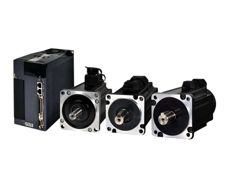
A servo motor is a motor (DC, brushless DC, or AC permanent-magnet synchronous) paired with a feedback device and a drive running a closed-loop control law. The encoder or resolver measures the actual shaft state; the drive compares it to the commanded value and adjusts current dozens of times per millisecond. A servo does not “count pulses to infer position” — it measures position. That distinction is the root of every other difference below.
How Each One Works — Step by Step
Stepper: pulse → step → position
- The controller sends a pulse train and a direction signal to the driver.
- The driver energizes the stator phases (A→B→A’→B’ for a 2-phase unit) in sequence, creating a rotating magnetic field.
- The rotor (permanent magnet + toothed iron) follows the field by one step angle per pulse.
- Total angular displacement = (number of pulses) × (step angle). Speed = (pulse frequency) × (step angle). No sensor is required.
- At standstill, with both windings held at rated current, the motor produces a fixed holding torque — it resists external load without power electronics doing work beyond holding current.
Servo: command → feedback → correction
- The controller issues a position/speed/torque command to the drive.
- The drive runs a three-loop structure: innermost current loop, middle speed loop, outer position loop (PID in each).
- The encoder reports actual position and speed back to the drive every feedback cycle (often 1–4 kHz).
- The drive computes error = target − actual and drives the motor to close it; if the load spikes, the servo draws more current to hold the setpoint.
- Because it measures rather than infers, the servo flags a fault if it cannot reach the target instead of silently drifting.
Feature Comparison Table
| Attribute | Stepper Motor | Servo Motor |
|---|---|---|
| Control architecture | Open-loop (pulse counting) | Closed-loop (encoder feedback) |
| Position certainty | Inferred; lost steps go unnoticed | Measured; error corrected in real time |
| Typical accuracy | Step angle 1.8°/0.9°; microstep to 0.01° resolution (not always accuracy) | Sub-arc-minute via 17–23-bit encoder |
| Torque at low speed | High holding & low-speed torque | Moderate; needs current to hold |
| Torque vs speed | Drops sharply above ~1000 rpm | Flat to rated speed; constant-power above |
| Overload capacity | None — loses steps if overloaded | 3×–10× rated short-term |
| Efficiency / power draw | Constant current even at idle (40–60% eff.) | Load-proportional (70–90% eff.) |
| Holding torque | Natural, no external power needed | Requires continuous current |
| Tuning required | No (set current & microstep) | Yes (PID autotune/stiffness) |
| Low-frequency resonance | Prone at 100–300 rpm; needs damping/microstep | Smooth across range |
| Relative system cost | Lower (no encoder, simple drive) | Higher (encoder + tuned drive) |
| Best fit | Repeatable PTP, low speed, budget | High speed, variable load, high dynamics |
Engineering Data: Efficiency, Temperature, and Torque Formulas
Efficiency and thermal behavior
A stepper draws full phase current whenever it is energized, whether moving or holding. At idle it produces zero mechanical output yet dissipates full copper loss — effective mechanical efficiency is 0% while holding and typically 40–60% in motion. A servo draws current proportional to load, so efficiency runs 70–90% under motion and near-zero at a static hold. The thermal consequence matters: an untended stepper can overheat at standstill, whereas a servo stays cool when unloaded.
| Metric | Stepper (typical) | Servo (typical) |
|---|---|---|
| Motion efficiency | 40–60% | 70–90% |
| Idle power draw | Full rated current | ~0 (no holding demand) |
| Insulation class (IEC 60034-1) | B (130°C) / F (155°C) | B (130°C) / F (155°C) |
| Allowable temp rise | ≤80 K (class B) / ≤100 K (F) | ≤80 K (class B) / ≤100 K (F) |
| Idle-current reduction | 20–50% after timeout (recommended) | N/A (already load-proportional) |
Torque formulas you should actually use
For a servo, the electromagnetic torque is set by the torque constant:
T = kt · Ia (N·m = N·m/A × A)
Mechanical output power is the torque–speed product:
P = T · ω = T · (2πn / 60) (W, with T in N·m, n in rpm)
For a stepper, the relevant figures are datasheet values: holding torque Th (at standstill, both phases energized) and rated torque at speed, which falls as back-EMF and winding inductance choke current at higher step rates. The step angle is fixed by construction:
θstep = 360° / (m · Nr) → a 2-phase hybrid with 50 rotor teeth gives 1.8°
Microstepping only subdivides the electrical commutation between full steps; it does not create new detent positions. Resolution per microstep = θstep / MS (e.g., 1.8° / 16 = 0.1125°), but the achievable accuracy is still bounded by the full-step detent geometry and by load.
Best Applications for Each
| Stepper — where it wins | Servo — where it wins |
|---|---|
| 3D printers, laser/plotter stages | Industrial robot arms, AGVs |
| Label applicators, indexing tables | High-speed CNC spindles |
| Medical pumps & syringe drives | Packaging & pick-and-place at high rate |
| Vending, camera sliders, telescopes | Aerospace actuators, gimbals |
| Cost-sensitive PTP automation | Variable-load or safety-critical motion |
The dividing line is the motion profile, not the industry. A stepper is the right answer for a slow, repeatable, predictable move; a servo is the right answer when speed, accel, or load variance push past what open-loop can guarantee. See our brush vs brushless guide and motor features hub for the wider motor map.
Step-by-Step Selection (with Worked Examples)
Selection checklist
- Define the motion profile: peak speed (rpm), acceleration, duty cycle, and holding requirement.
- Compute the torque demand: Ttotal = inertia torque (J·α) + friction + gravity/load torque.
- Check the speed region against each topology’s torque-speed curve.
- Quantify load variance — this decides open vs closed loop.
- Add a safety margin (30–50%); pick the frame/rating; then weigh cost.
Worked example A — stepper is correct
Requirement: a rotary index table, load inertia J = 2.0 × 10⁻³ kg·m2, angular acceleration α = 500 rad/s2, plus a 1.5 N·m gravity hold, max speed 180 rpm, low duty, budget-sensitive, repeatable.
- Inertia torque: Tacc = J·α = 2.0×10−3 × 500 = 1.0 N·m.
- Total demand at speed: 1.0 + 1.5 = 2.5 N·m.
- At 180 rpm a hybrid stepper delivers ~65% of its holding torque, so required holding torque Th ≥ 2.5 / 0.65 ≈ 3.85 N·m. Choose a NEMA 23 hybrid with Th = 4.5 N·m.
- Resolution: 1.8° × 1/16 microstep = 0.1125° per microstep (3200 microsteps/rev) — ample for indexing.
- Speed 180 rpm is well inside the stepper’s optimal band (<1000 rpm).
Verdict: a 4.5 N·m hybrid stepper fits with margin. A servo would cost 2–3× for no functional gain. Enable idle-current reduction to keep the table cool between indexes.
Worked example B — servo is mandatory
Requirement: a spindle needing 3500 rpm at a constant 3 N·m, with load that varies as the tool bites. A stepper’s torque collapses toward zero above ~1000–1500 rpm (back-EMF/inductance limit), so it physically cannot deliver 3 N·m at 3500 rpm. A servo holds ~3 N·m flat to its 5000 rpm rated speed and absorbs the bite spikes via its 3×–10× overload. Verdict: servo, no debate.
Quick decision matrix
| If your application… | Choose |
|---|---|
| Is slow, repeatable, load predictable, budget tight | Stepper (open-loop) |
| Needs fine smoothness at low speed | Stepper + microstepping |
| Must hold position without power | Stepper (natural holding torque) |
| Requires >1000–1500 rpm at torque | Servo |
| Has variable / unknown load or safety-critical moves | Servo (closed-loop) |
| Needs rapid accel / decel and high dynamics | Servo |
| Wants stepper economy but fears lost steps | Closed-loop stepper (encoder-added) |
Counter-intuitive takeaway: “precise” does not mean “servo.” A stepper is repeatable within its torque envelope; the instant load variance exceeds the margin it silently loses steps with no error flag. A servo is precise because it detects and corrects. And a servo is not automatically more efficient — at a partial-load hold, a stepper with idle-current reduction can beat a mistuned servo. Match the control law to the duty, not the topology to the brochure.
Common Engineering Mistakes
- Buying a servo for a fixed low-speed pick-and-place. You pay for encoder, tuning, and drive complexity you never use — a stepper does it cheaper.
- Sizing a stepper at exactly the load torque. Any variance causes lost steps. Apply 30–50% margin or move to closed-loop stepper / servo.
- Leaving full current on at idle. The motor bakes; insulation life halves per ~10°C over temperature (IEC 60034-1). Enable idle-current reduction.
- Assuming microstepping = higher accuracy. It interpolates between fixed detents; absolute accuracy stays bounded by the full-step geometry.
- Skipping servo tuning. Wrong PID gains cause hunting, overshoot, or instability — autotune and verify stiffness against the real load.
- Ignoring the stepper resonance band. 100–300 rpm can excite low-frequency oscillation; use microstepping or a mechanical damper.
Troubleshooting: Problem → Cause → Solution
| Problem | Cause | Solution |
|---|---|---|
| Stepper loses position / skips steps | Load > available torque, or resonance band | Add 30–50% torque margin; raise microstep; add damper; or switch to closed-loop stepper |
| Stepper overheats while holding | Full current held at standstill | Enable driver idle-current reduction (20–50%); verify class B/F limit |
| Servo oscillates / hunts | Position/speed loop gains mistuned | Run autotune against real inertia; lower gain or add damping |
| Servo overshoots setpoint | Position-loop gain too high | Reduce gain; check for backlash in the mechanical train |
| Stepper vibrates at low speed | Natural resonance 100–300 rpm | Use 1/8–1/32 microstepping; anti-resonance drive profile |
| Servo overcurrent / fault trip | Short, regen spike, or wrong inertia ratio | Check wiring; add regen resistor; keep load inertia within drive spec |
Frequently Asked Questions
Can a stepper motor replace a servo motor?
Often yes — for low-to-moderate speed, repeatable point-to-point moves with predictable load, a stepper (or closed-loop stepper) is cheaper and simpler. When speed, acceleration, or load variance exceeds the open-loop envelope, only a servo is safe.
Which is more efficient, servo or stepper?
At motion under load, servos run 70–90% because current tracks the load; steppers run 40–60% and waste full current at idle. But a stepper with idle-current reduction at a static hold can beat a mistuned servo. Efficiency depends on the duty, not the label.
Does microstepping increase positioning accuracy?
No. Microstepping increases resolution (finer electrical steps) and smoothness, but absolute accuracy is still bounded by the motor’s full-step detent positions and the mechanical load. It is not a substitute for an encoder.
Is a servo always more precise than a stepper?
A servo guarantees precision through feedback and fault detection. A stepper is precise only while load stays inside its torque margin; beyond that it drifts silently. For a known, light, repeatable move the stepper’s repeatability is often “precise enough.”
Which motor costs more and why?
Servos cost more because of the encoder/resolver, the tuned drive, and the engineering to close the loop. Steppers win on bill-of-materials: no feedback device and a simple pulse driver. The cost gap is typically 2–3× at equivalent frame size.
Can you run a servo motor open-loop?
Not meaningfully. Removing feedback defeats the servo’s purpose; you lose correction, overload protection, and fault detection, ending up with a worse, more expensive stepper. If you want open-loop, use a stepper.
Why Choose Greensky for Servo and Stepper Systems?
Greensky Power supplies hybrid stepper motors (1.8° and 0.9°, NEMA 8–34 frames), closed-loop stepper kits with integrated encoders, and BLDC/AC servo packages — all built to IEC 60034-1 insulation and NEMA MG 1 dimensions, with documented step angles, torque-speed curves, and thermal classes. Our OEM/ODM team helps integrators choose the right topology for the motion profile — a quiet 1/32 stepper for a medical pump, or a high-dynamic servo for a robot joint — and pairs either with speed reducers, standard flanges, or worm-gear stages at low MOQ. Compare topologies in our motor features hub, size steppers in our microstepping guide, or request a custom quote →.
Related Resources
Extend your selection work with these Greensky engineering guides:
- Stepper motor fundamentals — step angle, holding torque, microstepping
- How to set stepper driver subdivision — smoothness vs. usable torque
- Subdivision vs non-subdivision — when microstepping actually pays off
- Brush vs brushless DC motors — the servo-side motor map
- AC vs DC motors — choosing the servo prime mover
- Motor features hub — all four topologies compared
- Why a DC motor loses torque under load — torque-speed reality check
- Why robot arms need speed reducers — pairing motors with gearheads
- Custom electric motor & gear-motor solutions — low-MOQ OEM/ODM
References
- IEC 60034-1 — Rotating electrical machines, Part 1: Rating and performance (insulation classes, temperature rise). webstore.iec.ch/publication/56979
- IEC 60034-30-1 — Efficiency classes for rotating electrical machines (IE1–IE5). webstore.iec.ch/publication/91195
- NEMA MG 1-2016 — Motors and Generators (safety, thermal, mounting). nema.org/standards/view/mg-1-2016-motors-and-generators
- IEEE 112 — Standard Test Procedure for Polyphase Induction & DC Motors (efficiency/loss methods). standards.ieee.org/ieee/112/4703
- IEEE 43-2013 — Insulation Resistance Testing of Rotating Machinery. standards.ieee.org/ieee/43/4385
- U.S. Department of Energy — Motor & Drive Systems Efficiency. energy.gov/eere/motors
- SKF — Bearing and motor maintenance guidance. skf.com/us/products/bearings-units-housings
- Siemens — SIMOTICS electric motors & drive technology. siemens.com/global/en/products/drives/electric-motors.html
- maxon — Stepper motor application note. maxongroup.com/maxon/view/content/stepper-motors
- maxon — Brushed vs brushless / EC servo motors. maxongroup.com/…/brushed-vs-brushless-dc-motors-17012
- FAULHABER — Stepper motor technology. faulhaber.com/en/products/motors/stepper-motors
- Yaskawa — Motor & drive technical documents. yaskawa.com/downloads/search-index
