
Why Do Brushed Motors Spark? The Complete Engineering Guide
Quick Answer
Brushed motors spark because of mechanical commutation. As the carbon brushes slide from one commutator segment to the next, they repeatedly break the current in the armature windings. Because each winding is an inductor, the sudden interruption forces a rapid change in current that induces a high voltage spike — the reactance voltage or “inductive kick.” This voltage ionizes the tiny air gap opening between the brush and the departing segment, producing a small electric arc, or spark.
A weak, discontinuous spark at the trailing edge of the brush is normal; large, continuous, ring-shaped sparking is a fault caused by worn brushes, wrong brush grade, incorrect brush pressure, a dirty commutator, or overload. International standards IEC 60034-1 and NEMA MG 1 define the sparkless commutation zone (the “black band”) that motor makers design toward.
What Is Commutation, and Why Does It Cause Sparking?
A brushed DC motor turns because the direction of current in the rotating armature windings must be reversed at exactly the right moment. This job is done by two parts working together: the commutator and the brushes.
Commutator (not a slip ring)
The commutator is a copper ring on the rotor shaft that is split into insulated segments. Each pair of opposing segments connects to a specific winding. A common mistake — including in many older articles — is to call this part a “slip ring.” That is incorrect: a slip ring is a continuous, unsegmented ring used in AC machines and wound-rotor motors to pass a steady current to a rotating part. A commutator is segmented precisely so it can reverse (commutate) the winding current. Sparking is a direct consequence of that segmented switching action.
Brushes
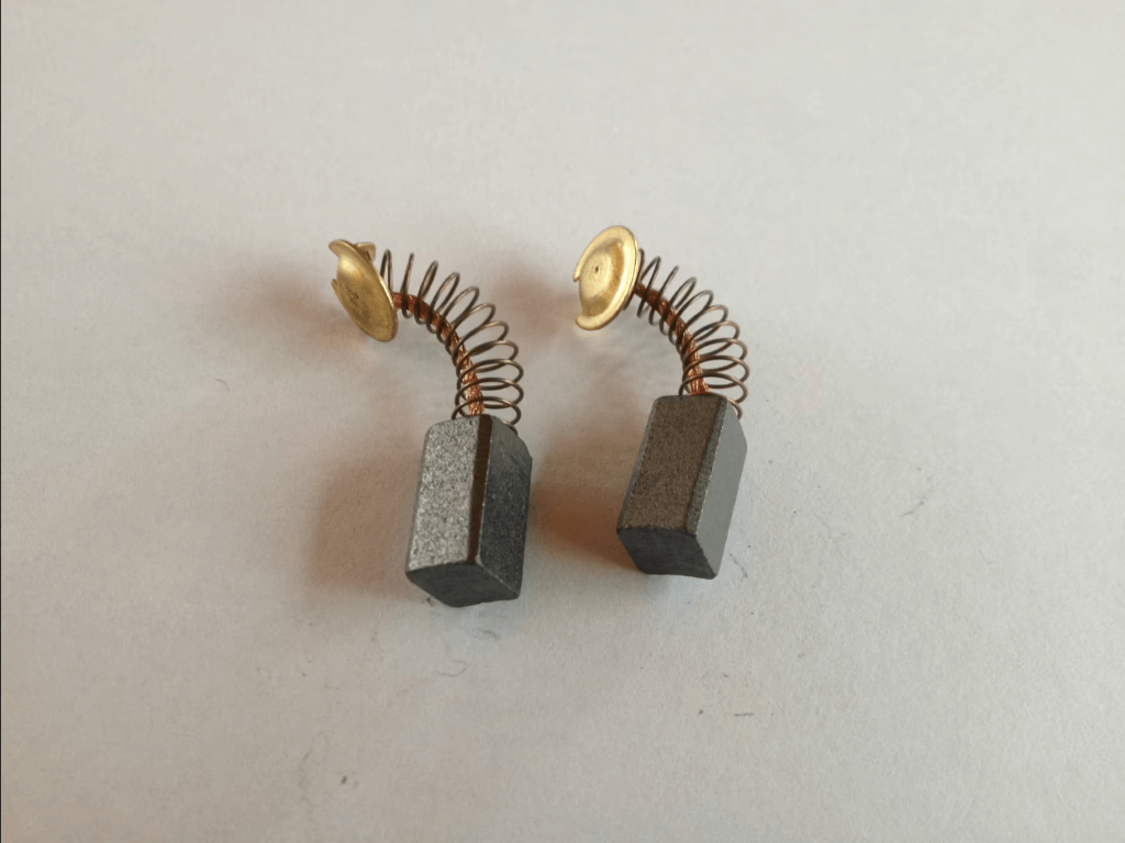
Brushes are stationary blocks of conductive material — usually a graphite–copper composite (about 50% copper in small motors, per maxon’s DC motor commutation documentation) or a plated precious-metal contact for micro-motors — spring-loaded against the spinning commutator. As the rotor turns, each brush slides across the segment gaps, momentarily short-circuiting and then re-routing current.
Reactance voltage and inductive kick
The core electrical cause of sparking is reactance voltage (also called the inductive kick). An armature winding stores energy in its magnetic field. When the brush leaves a segment, the circuit opens abruptly and the collapsing field induces a voltage spike e = −L·(di/dt). If this spike exceeds the dielectric strength of the opening air gap (roughly 3 kV/mm at the microscopic scale involved), the air ionizes and current jumps the gap as a spark. This is why sparking is worse at high speed, high load, and with high-inductance windings.
How a Spark Forms: Step-by-Step
- Current flows through the winding. A brush feeds DC current into an armature coil via one commutator segment, energizing the coil and building a magnetic field.
- The brush reaches a segment gap. As the rotor turns, the brush begins to bridge two segments — the coil is momentarily short-circuited so its current can start reversing (this interval is the “commutation period”).
- The circuit opens. The brush lifts off the departing segment. The coil current has not fully reversed, so a “residual current” remains that must be interrupted.
- Inductive kick fires. The winding inductance resists the change, inducing a high reactance voltage across the shrinking air gap. Armature reaction shifts the magnetic neutral, worsening the imbalance.
- The air ionizes → spark. The voltage breaks down the gap and an arc discharges. Research on high-speed DC motors measured a typical arc duration of about 42 µs and residual current near 0.55 A across 1,000–5,000 rpm (Sawa et al., 2017 IEEE Holm Conference).
This sequence repeats for every segment on every rotation — thousands of times per minute — which is why a brushed motor produces a near-continuous shower of tiny sparks inside its housing.
Normal Sparking vs. Abnormal Sparking
Not all sparking is a fault. The key skill is telling harmless micro-sparks from destructive arcing. NEMA MG 1 and DC machine practice grade commutation on a spark scale from ½ (pinpoint) to 3 (heavy, destructive).
| Characteristic | Normal Micro-Sparking | Abnormal / Fault Sparking |
|---|---|---|
| Location | Trailing edge of the brush only | Whole brush face; ring fire around commutator |
| Appearance | Small, blue-white, discontinuous pinpoints | Large, yellow-red, continuous arcs |
| Spark grade (NEMA scale) | ½ – 1 | 1¼ – 3 |
| Sound | None or faint hiss | Crackling, buzzing, unstable |
| Effect on life | Negligible | Rapid brush & commutator erosion |
| Typical cause | Inherent inductive commutation | Overload, wrong brush, bad contact, short |
| Action needed | None — monitor | Stop & inspect immediately |
Brushed vs. Brushless: Why One Sparks and the Other Doesn’t
The single biggest reason engineers migrate from brushed DC motors to brushless DC (BLDC) motors is the elimination of the sparking commutation contact. Learn more in our guide to the difference between AC and DC motors.
| Feature | Brushed DC Motor | Brushless DC (BLDC) |
|---|---|---|
| Commutation method | Mechanical (brush + commutator) | Electronic (controller + Hall/sensorless) |
| Sparking | Yes — inherent | None |
| EMI / RFI | High (each spark is an RF burst) | Low (PWM noise, filterable) |
| Typical peak efficiency | 65–80% | 85–92%+ |
| Maintenance | Periodic brush replacement | Essentially maintenance-free |
| Service life | 1,000–5,000 h (brush-limited) | 10,000–50,000 h (bearing-limited) |
| Explosive-atmosphere use | Restricted (ignition risk) | Preferred |
| Relative cost | Low | Higher (needs controller) |
For a deeper look at BLDC trade-offs, see the disadvantages of brushless DC motors and why brushless DC motors have 3 wires.
Engineering Data: Formulas, Temperatures & Brush Grades
Key formulas that govern sparking
| # | Quantity | Formula | Meaning |
|---|---|---|---|
| 1 | Inductive kick (reactance voltage) | e = −L·(di/dt) | Voltage spike driving the arc; higher L or faster switching = bigger spark |
| 2 | Commutation period | tc = b / vc | Contact time (brush width b ÷ commutator surface speed vc); shrinks with speed |
| 3 | Contact heat (Joule) | Q = I²·R·t | Heat at the interface; rises with the square of current density |
| 4 | Back-EMF | E = Ke·ω | Sets operating current; low back-EMF at start = high current = more spark |
| 5 | Torque | T = Kt·I | Higher load current means more commutated energy per event |
| 6 | SKF bearing life | L10h = (10⁶/60n)·(C/P)³ | Bearing rating; misalignment/vibration accelerates brush sparking too |
Brush systems compared (maxon commutation data)
| Parameter | Graphite Brush | Precious-Metal Brush |
|---|---|---|
| Composition | ~50% graphite + 50% copper | Silver-plated bronze spring |
| Contact resistance | Higher (helps limit current spikes) | Very low (~50 mΩ) |
| Best for | High current density, higher power | Low current, low voltage, signal-clean micro-motors |
| Spark sensitivity | Tolerant — patina self-heals | Sensitive — needs CLL capacitor suppression |
| Service life driver | Graphite acts as lubricant | Brush fire drastically shortens life |
maxon reduces brush fire further by using an odd number of commutator segments (e.g., 7 bars on the DC-max 16), so less energy is switched per commutation event, cutting both sparking and EMI.
Insulation class & temperature limits (IEC 60034-1)
Sparking generates localized heat, so insulation-class limits matter. Greensky’s standard round DC brush motors use Class B insulation (130 °C, ≤80 K rise).
| Insulation Class | Max Hot-Spot Temp | Typical Temp Rise (40 °C ambient) | Example |
|---|---|---|---|
| Class A | 105 °C | 60 K | Legacy small motors |
| Class B | 130 °C | 80 K | Greensky GSD55ZYT DC brush motor |
| Class F | 155 °C | 105 K | maxon DC-max (125 °C max winding) |
| Class H | 180 °C | 125 K | Industrial / high-duty DC motors |
Spark-suppression techniques
- RC snubber / CLL capacitor — absorbs the inductive-kick energy across the brush gap (used in maxon precious-metal systems).
- Interpoles (commutating poles) — in larger DC machines, auxiliary poles generate a counter-voltage that cancels reactance voltage. A Hitachi study verified near sparkless commutation on a 2,000 kW DC motor using tuned interpole flux (Koharagi et al., 1993).
- Brush-grade matching — hardness and conductivity matched to voltage/current.
- Correct brush pressure — uniform across all brushes, within ±10% of spec.
- Neutral-plane adjustment — align brushes with the magnetic neutral axis under load.
Where Brushed Motors Are Fine — and Where Sparking Is a Deal-Breaker
| Application | Sparking Acceptable? | Why |
|---|---|---|
| Automotive starters, seats, windows | Yes | Sealed, low duty cycle, cost-sensitive |
| Power tools, vacuum cleaners | Yes | High torque, short run time, low cost |
| Toys, hobby RC | Yes | Cheap, simple 2-wire drive |
| Medical / lab instruments | No | EMI corrupts sensitive electronics → use BLDC |
| Explosive / dusty atmospheres (ATEX) | No | Spark is an ignition source → use BLDC or Ex-rated |
| Continuous industrial duty (S1) | Limited | Brush wear forces frequent maintenance |
Selection Guide: Minimizing Sparking in Your Design
- Define duty and environment. Intermittent + sealed favors brushed; continuous, EMI-sensitive, or hazardous favors BLDC.
- Estimate operating current. Use T = Kt·I to size current; keep it below the brush’s rated current density to limit Q = I²Rt heating.
- Choose the brush grade. Graphite–copper for higher power; precious metal for clean low-current signals.
- Cap the speed. Brush wear rises sharply above ~3,000 rpm (Sawa 2017); add a gearbox instead of over-speeding.
- Verify thermal margin. Confirm winding stays within the insulation-class limit (Class B/F) under worst-case load.
- Add suppression. Specify RC snubber/CLL and EMI filtering where required by the application.
Common Engineering Mistakes
| Mistake | Consequence | Correct Practice |
|---|---|---|
| Calling the commutator a “slip ring” | Misdiagnosis; wrong repair path | Commutator is segmented; slip rings are continuous (AC use) |
| Ignoring all sparking as “normal” | Missed ring-fire failures | Grade the spark (NEMA scale); act above grade 1 |
| Wrong brush grade for current | Excess arc erosion or high losses | Match graphite vs precious metal to duty |
| Uneven / excessive brush pressure | Bounce, hot spots, uneven wear | Set uniform pressure per datasheet (±10%) |
| Over-speeding a brushed motor | Rapid brush/commutator wear | Gear down; respect max speed rating |
| Using brushed motors in EMI/ATEX zones | Interference or ignition hazard | Switch to BLDC or Ex-rated designs |
Troubleshooting: Problem → Cause → Solution
| Problem | Likely Cause | Solution |
|---|---|---|
| Heavy sparking on one brush | Uneven brush spacing / stuck brush | Re-space brushes; free the holder; renew brush |
| Ring fire around commutator | Overload, shorted winding, wrong polarity of poles | Reduce load; test windings; correct pole sequence |
| Sparking increases with load | Armature reaction shifting neutral plane | Adjust brush neutral position; add/tune interpoles |
| Continuous crackling & noise | Rough/dirty commutator, carbon buildup | Clean and re-surface commutator; undercut mica |
| Rapid brush wear | Excess pressure or over-speed | Set correct pressure; gear down speed |
| Brush chatter / bounce | Weak/softened spring, vibration | Replace spring; check bearings/alignment |
| Motor sparks then stalls | Open/short in armature coil | Bar-to-bar test commutator; rewind if needed |
| EMI in nearby electronics | RF bursts from arcing | Add RC snubber, capacitors, shielding — or use BLDC |
Frequently Asked Questions
Is it normal for a brushed motor to spark?
Yes. A small, blue-white, discontinuous spark at the trailing edge of the brush is a normal by-product of mechanical commutation and has little effect on motor life. Large, continuous, yellow-red arcing or ring fire is abnormal and signals a fault.
Why exactly does the spark happen?
Because the armature windings are inductors. When a brush breaks contact with a segment, the winding’s collapsing magnetic field induces a high reactance voltage (e = −L·di/dt) that ionizes the opening air gap, producing an arc.
Do brushless motors spark?
No. BLDC motors replace the mechanical brush/commutator with electronic commutation, so there is no sliding contact to arc. This is the main reason they are chosen for EMI-sensitive and explosive environments.
Does sparking reduce motor efficiency?
Yes. Every spark is energy lost as heat, light, and radio-frequency noise instead of torque. Brushed motors typically peak at 65–80% efficiency versus 85–92%+ for comparable BLDC motors.
How do I reduce sparking in a brushed motor?
Match the brush grade to the current, set uniform brush pressure, keep the commutator clean and true, respect the rated speed, align the brushes to the neutral plane, and add an RC snubber or CLL capacitor for suppression.
Can excessive sparking damage the motor?
Yes. Heavy arcing rapidly erodes both the carbon brushes and the copper commutator, creates conductive carbon dust, and can escalate to a destructive “ring fire” that burns out the motor.
Why Choose Greensky for Brushed & Brushless Motors?
Since 2011, Greensky Power has engineered micro brushed DC motors, BLDC motors, stepper motors, gearboxes and controllers for customers in over 50 countries. When sparking, EMI, or brush life is critical to your project, our engineering team helps you choose — and if needed, migrate — to the right technology.
- PhD-led R&D: 8 engineers focused on commutation, control and low-EMI design.
- Correct brush engineering: graphite–copper or precious-metal systems matched to your duty.
- 100% individual testing: every motor tested on dynamometers in silent rooms.
- Standards compliance: ISO, CE and energy-efficiency certified; designed to IEC 60034 / NEMA MG 1 practice.
- Brushed-to-BLDC migration: full OEM/ODM support when you need a spark-free upgrade.
- Local support: North America & Europe engineering and after-sales through United Motion Inc.
References
- IEC 60034-1, Rotating electrical machines — Rating and performance. https://webstore.iec.ch/publication/60034-1
- NEMA MG 1, Motors and Generators. https://www.nema.org/standards/view/motors-and-generators
- NEMA MG 1-2009 (full text, law.resource.org). https://law.resource.org/pub/us/cfr/ibr/005/nema.mg-1.2009.pdf
- Xiang, Chai & Li, “A Controlled Mechanical–Electronic Hybrid Commutation Theory,” IEEE Trans. Power Electronics, 2022. https://doi.org/10.1109/TPEL.2021.3135891
- Sawa et al., “Commutation characteristics and brush wear of DC motor at high rotation speed,” 2017 IEEE Holm Conference. https://doi.org/10.1109/holm.2017.8088082
- Sawa, Liu & Ueno, “Influence of Arc Discharge on Carbon Commutator and Brush Wear,” 2012 IEEE Holm Conference. https://doi.org/10.1109/holm.2012.6336587
- Koharagi et al., “Verification of Commutation Spark Reduction for Brushes of Large DC Motors,” IEEJ Trans. IA, 1993. https://doi.org/10.1541/ieejias.113.1094
- maxon group, DC Motor: Design, Variants, Properties, Commutation (technical documentation). https://support.maxongroup.com/hc/en-us/article_attachments/4415193502226
- maxon group, DC-max brushed DC motor datasheet. https://www.maxongroup.com/medias/sys_master/root/8846113472542/20-CN-V2-100.pdf
- U.S. Department of Energy, 10 CFR Part 431 — Energy Conservation Program for Electric Motors. https://www.energy.gov/eere/motors
