
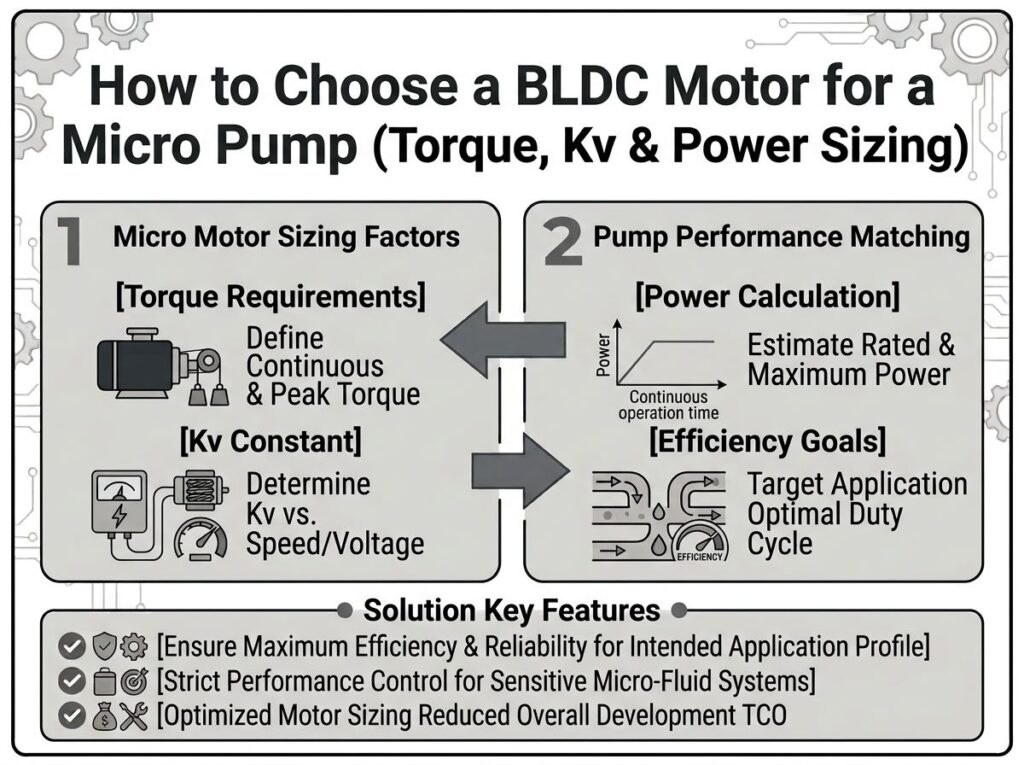
How to Choose a BLDC Motor for a Micro Pump: Torque, Kv & Power Sizing
P = T × n / 9.55 / η, then pick a motor whose continuous torque at the required speed clears that demand with a ≥15% margin.Match the winding to the available bus voltage through the Kv speed constant — remembering Kv is a gearing choice, not a performance rating — and select a slotless BLDC when you need silent, cog-free low-flow metering or a slotted BLDC when you need torque density on a budget. For most compact, low-flow, low-power OEM equipment the answer is a 12–24 V, 10–150 W brushless motor with Class F insulation and either Hall or sensorless commutation.
In this guide
- What Is a BLDC Motor for a Micro Pump?
- How the BLDC Motor + Micro Pump Power Path Works
- Motor Type Comparison: Slotless vs. Slotted vs. Stepper vs. Brushed
- Engineering Data: Torque, Kv, Power & Efficiency
- Best Applications: Miniature Fluid Systems & OEM Equipment
- How to Select a Micro-Pump BLDC Motor (8 Steps)
- Common Engineering Mistakes
- Troubleshooting: Problem → Cause → Solution
- FAQ
- Why Choose GreenSky?
- References
What Is a BLDC Motor for a Micro Pump?
A BLDC motor for a micro pump is a small, electronically commutated permanent-magnet motor that drives a compact fluid head — a magnetic-drive centrifugal or gear pump, a diaphragm pump, or a peristaltic head — in an OEM instrument or device. It is not a special motor family; it is a brushless motor optimised for the micro-pump duty: small physical size, low flow, low power, quiet operation, and long, maintenance-free life.
Three properties make BLDC the default choice over brushed DC or AC induction for this duty:
- No brushes. Electronic commutation removes brush wear, arcing, dust and audible noise — the exact things that disqualify brushed motors in clean, quiet medical and analytical instruments.
- Variable speed. Flow tracks motor speed, so a single BLDC motor + controller meters from near zero to full flow without a mechanical throttle (see how a micro magnetic pump works).
- High efficiency at small size. Permanent-magnet rotors eliminate rotor copper loss, so a 12–24 V BLDC of 10–100 W still reaches 80–90% efficiency — the margin that keeps a battery-powered device running and its thermal load low.
For the compact end of the range the motor is often integrated directly into the pump head — a magnetic coupling drives the impeller or gear set through a containment shell, so there is no shaft seal at all. The motor selection question then becomes: what torque, speed, voltage and thermal rating does the hydraulic load actually require? The rest of this guide walks through that sizing logic.
How the BLDC Motor + Micro Pump Power Path Works
Follow the power from the DC bus to the fluid. Each stage has a loss, and each loss becomes a selection criterion.
- The controller commutates the windings. A small electronic drive (often integrated) energises the three phases in sequence, using Hall sensors or back-EMF to know the rotor angle. Field-oriented control (FOC) gives smooth sinusoidal current and quiet, cog-free rotation.
- Current produces torque. Torque is proportional to phase current:
T = Kt × I, whereKtis the torque constant (N·m/A). The motor must supply the pump’s demand torque at the target speed without exceeding its continuous current rating. - Torque crosses to the fluid. In a magnetic-drive pump the torque is transmitted by a magnetic coupling across a containment shell; in a direct-shaft head it passes through the motor shaft. Either way, the hydraulic load sets the torque — this is the same power path described in our magnetic vs. conventional gear pump comparison.
- The pump moves fluid. A centrifugal head follows the affinity laws (
Q ∝ N,H ∝ N²,P ∝ N³); a gear head delivers a fixed volume per revolution (Q = D × N × ηv) and needs more torque as pressure and viscosity rise. - Losses become heat. Copper loss (
I²R), iron loss and coupling eddy-current loss (5–8% on a metallic shell) all raise the winding temperature. The insulation class — B (130 °C), F (155 °C) or H (180 °C) per IEC 60034-1 — sets the ceiling the motor must stay under.
Motor Type Comparison: Slotless vs. Slotted vs. Stepper vs. Brushed
Four drive technologies compete for the micro-pump role. The table contrasts them on the parameters that matter for compact, low-flow duty.
| Attribute | Slotless (coreless) BLDC | Slotted BLDC | Closed-loop stepper | Brushed DC |
|---|---|---|---|---|
| Cogging torque | None (ironless) | Low–moderate | Detent steps | None (but brush ripple) |
| Noise / smoothness | Quietest, smooth | Good | Audible steps at low speed | Brush noise + arc |
| Efficiency | High (no iron loss) | High | Moderate | Low (50–65%) |
| Torque density | Lower | Higher | High at low speed | Moderate |
| Low-speed metering | Excellent | Good | Excellent (open-loop capable) | Fair |
| Life / maintenance | 20,000+ h, none | 20,000+ h, none | Long, no wear | Brush replacement |
| Relative cost | Highest | Mid | Mid | Lowest |
| Best micro-pump use | Precision dosing, lab, medical | Higher-pressure transfer | Nanoliter dispensing | Budget, intermittent duty |
The usual recommendation: slotless BLDC for metering and quiet OEM instruments, slotted BLDC for higher-pressure continuous duty, and a closed-loop stepper only when the job is sub-µL precision dispensing rather than continuous flow. The slotless motors from Maxon and FAULHABER are the industry reference platforms (see our top brushless motor manufacturers rundown); for a deeper read on commutation choices, see our Hall sensor vs. sensorless BLDC comparison.
Engineering Data: Torque, Kv, Power & Efficiency
Every micro-pump motor decision reduces to a handful of equations and thermal limits. These are the ones that actually get used in sizing.
The four constants
| Quantity | Formula | What it tells you |
|---|---|---|
| Torque | T = Kt × I | Current needed for a given torque |
| Back-EMF | E = Ke × ω | Voltage generated, hence top speed |
| Kv ↔ Kt conversion | Kt [N·m/A] = 9.5493 / Kv [rpm/V] | Turns a Kv rating into engineering units |
| Motor constant | Km = Kt / √R | Torque per √watt — the fair comparison metric |
The two facts that trip people up: in SI units Kt and Ke are the same physical constant expressed from the mechanical and electrical sides, and Kv is inversely proportional to Kt — a higher Kv number means less torque per amp. A 1000 Kv motor produces 0.00955 N·m/A; a 100 Kv motor of the same frame produces 0.0955 N·m/A, ten times as much. When you rewound one frame to different Kv values, the copper loss for a fixed torque stays identical — so Kv does not change efficiency, it only changes the current and voltage the drive must handle. Compare candidates by Km, not by Kv.
Sizing power from the hydraulic load
The shaft power the motor must deliver is:
P (W) ≈ T (N·m) × n (rpm) ÷ 9.55 ÷ η
where η folds in pump volumetric/hydraulic efficiency and, for a magnetic-drive head, the coupling efficiency (typically ~80–85% on a non-metallic shell, dropping 5–8% on a metallic one). Worked example: a gear head needs 0.3 N·m at 3000 rpm with η = 0.7 → P ≈ 0.3 × 3000 ÷ 9.55 ÷ 0.7 ≈ 135 W, so a 60–150 W BLDC is the right bracket. For a gear pump you can also back-solve displacement from flow: D = Q / (n × ηv), with volumetric efficiency ηv ≈ 0.85 for low-viscosity fluids and up to 0.93 for viscous ones.
Efficiency and thermal limits by frame size
| Frame / rating | BLDC peak efficiency | Brushed equivalent | Dominant loss |
|---|---|---|---|
| 12–22 mm, <20 W | 70–80% | 55–65% | Copper |
| 22–42 mm, 20–100 W | 80–87% | 68–75% | Copper + friction |
| 42–80 mm, 100–500 W | 85–91% | 75–80% | Balanced |
Insulation classes follow IEC 60034-1: Class B = 130 °C, Class F = 155 °C, Class H = 180 °C maximum winding temperature. Most micro-pump motors are Class B or F; pick F when the pump runs hot fluid or continuous duty. Peak efficiency occurs near 70–80% of rated torque, so a motor loafing at light load can sit 10–15 points below its headline figure. Small motors are inherently less efficient than large ones — do not expect a 22 mm pump motor to match an 80 mm industrial unit’s efficiency. The same efficiency-vs-load logic for battery systems is worked through in our motor efficiency and battery runtime guide.
Best Applications: Miniature Fluid Systems & OEM Equipment
The BLDC micro-pump motor earns its place wherever small size, low flow, low power and quiet, maintenance-free life are the deciding factors:
- Medical & analytical instruments. Diagnostic analyzers, dialysis, reagent dosing and infusion where flow must be leak-free, pulseless and accurate to ±0.3–2%. Motors here follow IEC 60601-1 / ISO 13485 expectations.
- Electronics thermal management. Liquid-cooling loops for servers, lasers and power electronics — a low-power 12/24 V BLDC circulating coolant quietly for years — the same drive logic that keeps an AGV traction motor running on battery, but scaled down to a few watts.
- Fuel cells & hydrogen systems. Recirculation and metering of hydrogen or methanol where the sealless magnetic drive eliminates leaks of a flammable fluid.
- Portable & battery devices. Coffee machines, personal-care devices, ink-jet and spray systems — where low power draw and 3.7–24 V operation extend runtime.
- Chemical dosing & printing. Metering reagents, adhesives and inks at single-digit mL/min to L/min, where gear-type heads give flow proportional to speed.
The common thread is integration: the motor is supplied as a compact head with a built-in or paired speed controller, a 0–10 V / PWM setpoint, and often a tachometer or FG signal for closed-loop flow control — exactly what an OEM needs to drop the assembly into an instrument.
How to Select a Micro-Pump BLDC Motor (8 Steps)
- Define the operating point. Write down min/nominal/max flow, the system back-pressure at each, and the fluid (name, viscosity, temperature, particle content). This is the load profile everything else follows.
- Compute demand torque. From pressure and displacement (gear) or the impeller curve (centrifugal), work out the torque the pump needs at the rated speed, including the viscosity and pressure margin.
- Size the shaft power. Apply
P = T × n / 9.55 / ηwith a realistic combined efficiency, then add a 15–25% service margin. - Choose the voltage. Match the motor to the machine’s existing bus — 12 V (portable), 24 V (industrial/medical), 48 V only when power demands it. The voltage-vs-speed trade-off is the same one covered in our battery voltage selection guide.
- Pick Kv and winding. Select a Kv so that
Kv × voltagelands the no-load speed ~15–25% above the required loaded speed (accounting for speed drop under load). Low-Kv for torque-heavy duty, high-Kv for high-speed low-torque duty. - Choose the motor type. Slotless BLDC for quiet metering, slotted BLDC for higher-pressure continuous duty, closed-loop stepper for sub-µL dispensing.
- Confirm thermal and duty. Check the continuous torque at the operating point stays within the winding’s insulation class (Class F = 155 °C), and set the duty (IEC S1 continuous vs. S3 intermittent) to the real run pattern.
- Verify feedback and controller. Decide Hall vs. sensorless (sensorless needs a start-up ramp, Hall gives full torque from standstill), and confirm the drive supports the current, PWM/FOC mode and any 0–10 V or fieldbus interface the instrument needs.
For a worked example and the motor series GreenSky supplies for this exact duty, see our micro magnetic gear pump motors selection table, and the underlying sizing math in BLDC motor basics and sizing.
Common Engineering Mistakes
- Selecting by Kv or power alone. Kv is a winding choice, not a capability; two motors can have identical continuous torque with very different Kv. Compare by Km and continuous torque, not by headline RPM or watts.
- Ignoring the torque margin. Sizing the motor to exactly the nominal torque leaves nothing for viscosity spikes, cold-start fluid, or pressure transients — the motor stalls or overheats the first time conditions change.
- Forgetting volumetric efficiency. Assuming the pump delivers its geometric displacement ignores internal slip, which rises with pressure and low viscosity. Use
ηv ≈ 0.85for thin fluids, not 1.0. - Running a sensorless motor from standstill. Back-EMF is too weak near zero speed to detect rotor angle. If the pump must start loaded or at low speed, specify Hall sensors or an encoder.
- Overlooking the insulation class. A Class B motor (130 °C) on a hot-fluid or continuous-duty pump runs into thermal derating quickly; step to Class F for headroom.
- Mismatching the bus voltage. Choosing a 48 V motor for a 24 V machine forces a DC-DC converter and wastes efficiency — pick the winding to the bus that already exists.
- Neglecting dry-run and solids limits. On a magnetic-drive head the motor-side bearings are fluid-lubricated; dry running or abrasive particles destroy them. The motor selection must respect the pump’s dry-run and particle limits.
Troubleshooting: Problem → Cause → Solution
| Problem | Likely cause | Solution |
|---|---|---|
| Motor stalls at low speed / won’t start | Sensorless commutation, back-EMF too weak | Use Hall sensors or encoder; add open-loop start-up ramp |
| Winding overheats in normal duty | Torque margin too small; Class B on hot service | Re-size to higher continuous torque; step to Class F |
| Flow drops as back-pressure rises | Volumetric slip / undersized torque | Recompute ηv; raise motor torque or displacement |
| Audible noise or vibration | Slotted cogging; block commutation | Switch to slotless BLDC or FOC (sinusoidal) drive |
| Short bearing life / seizure | Dry running or abrasive particles | Add dry-run protection; filter fluid; check materials |
| High current, low efficiency | High-Kv winding on a low-voltage bus | Rewind to a lower-Kv, higher-Kt winding for the bus |
FAQ
How do I calculate the right Kv for my pump motor?
Estimate the no-load speed you need as Kv × voltage, and target a no-load speed roughly 15–25% above the required loaded speed to cover load drop. Rearranged: Kv ≈ (loaded rpm × 1.2) / bus voltage. A 24 V motor that must run ~2500 rpm under load wants a Kv near 2500 × 1.2 / 24 ≈ 125.
Slotless or slotted BLDC — which is quieter for a micro pump?
Slotless. Because the winding has no iron teeth, there is no cogging torque and no slot ripple, so rotation is smoother and quieter — which is why slotless BLDC motors from Maxon (EC series) and FAULHABER are the reference choice for medical and analytical pump heads. Slotted BLDC wins on cost and torque density when higher pressure is needed.
What duty cycle applies to a micro pump motor?
Continuous-circulation pumps (cooling loops, 24/7 analyzers) run S1 continuous duty and must be rated for it. Intermittent dosing or sampling pumps are S3 (intermittent periodic), where RMS torque — not peak — governs heating. Per IEC 60034-1, pick the duty class that matches the real run pattern or the winding runs hot.
Why does my motor draw more current than the catalogue says?
Two usual reasons. First, the catalogue current is at a stated operating point, and your load (viscosity, back-pressure, fluid temperature) is different. Second, a high-Kv motor needs more current for the same torque than a low-Kv one — I = T / Kt. Confirm you are comparing continuous torque at your actual speed, not the no-load figure.
Can I run a micro pump BLDC motor directly on battery voltage?
Only if the controller tolerates the battery’s full range. A nominal 12 V system can swing from ~9 V to 14 V+ across charge states, and a motor wound for a fixed 12 V may not reach full speed at the low end or may over-speed at the top. Specify the winding and controller for the battery’s operating window, or add a regulated bus.
Do small BLDC pump motors meet energy-efficiency rules?
Most micro-pump BLDC motors are below the power thresholds of the main motor-efficiency regulations — U.S. DOE 10 CFR 431 covers small electric motors and 1–500 hp motors, while IEC 60034-30-1 defines IE1–IE5 classes for line-operated AC motors. Even where not mandated, specifying an IE4-class or 85%+ efficient BLDC is the practical way to keep a battery device running and its thermal load down.
Why Choose GreenSky?
GreenSky Power manufactures the BLDC and PMSM drive motors and drive electronics that sit inside compact, low-flow, low-power pump heads. Our micro-pump range spans 12–42 mm frames, 3.7–48 V, ~10–400 W, with slotless and slotted BLDC, closed-loop stepper, and explosion-proof options, paired to magnetic gear-pump heads from 0.6 to 5.0 mL/rev. Every motor is built for OEM integration: IE4-class efficiency, Class F/H insulation, IP54–IP65 protection, CE/RoHS/REACH compliance for export (see our CE compliance guide), and co-design support for custom windings, shafts, connectors and integrated controllers — the same OEM manufacturing approach we apply to every drive we ship. We size the motor and the pump together against your flow, pressure and duty profile, then validate the pair on your actual fluid.
Need a BLDC motor matched to your micro pump?
Send your flow, pressure, fluid and bus voltage — we’ll return a torque-verified motor + pump recommendation with a technical data sheet.
Contact GreenSky engineering →Get Free Quote
References
- IEC 60034-1:2022 — Rotating electrical machines, Part 1: Rating and performance (duty cycles S1–S10, insulation classes, temperature rise)
- IEC 60034-30-1 — Efficiency classes of line-operated AC motors (IE1–IE5)
- NEMA MG 1-2021 — Motors and Generators (small motor frames, efficiency tables)
- U.S. DOE 10 CFR Part 431 — Energy conservation standards for electric motors and small electric motors
- M. Ooshima and C. Takeuchi, “Magnetic Suspension Performance of a Bearingless Brushless DC Motor for Small Liquid Pumps,” IEEE Transactions on Industry Applications, vol. 47, no. 1, pp. 72–78, 2011.
- M. Ooshima and C. Takeuchi, “Magnetic suspension performance of a bearingless brushless DC motor for small liquid pumps,” Proc. ICEMS 2009, Tokyo, Japan.
- IEA — Energy Efficiency: motor-driven systems policy and technology reports
- SKF — Bearing selection and life guidance for small electric motors and pumps
- Siemens — SIMOTICS low-voltage motors and drive technology documentation
- Yaskawa — GA500 microdrive and permanent-magnet motor control documentation
