
9S10P vs 12S8P: Choosing a Robotic Mower Blade Motor
Quick Answer
At equal copper and magnet mass, a 9-slot 10-pole (9S10P) stator makes about 9% more torque per ampere than a 12-slot 8-pole (12S8P) one. We chose 12S8P for a 90 W robotic mower blade drive anyway. Its lowest radial force order is 4 instead of 1, so it never shakes the housing as a rigid body. Its 30° slot pitch is exactly 120° electrical, so three Hall sensors drop into three slot openings with the lamination as the datum. The cost is 3–4× more cogging, 24 cycles per revolution instead of 90. The delivered unit — 21 V, 4,500 rpm, 0.192 N·m, 490 g — measured 41.5 dB(A) at 30 cm, no load.
- What 9S10P and 12S8P Actually Mean
- Winding Factor: Quantifying 9S10P’s Advantage
- Cogging Torque: Where 9S10P Wins
- Unbalanced Magnetic Pull: The GCD Rule
- Why Force Order Beats Frequency at Blade Speed
- Hall Sensor Placement: The Geometry That Decides
- Recovering the 9% Torque Gap in Design
- Pole Shaping and the Unequal Air Gap
- Reading a Real Nameplate: The 90 W Case
- Side by Side: When Each One Wins
- What 41.5 dB at 30 cm Really Means
- Selection Checklist for Mower Blade Motors
- References
- FAQ
What 9S10P and 12S8P Actually Mean
The naming is literal. The first number is stator slots, the second is rotor poles, so 9S10P is nine slots and ten poles and 12S8P is twelve slots and eight poles. Both are three-phase, both use one coil per tooth, and both are fractional-slot concentrated windings. Their slot and pole counts lead to different electromagnetic behaviour.
Slots per pole per phase is q = Z / (3 × 2p): 0.3 for 9S10P, 0.5 for 12S8P. Any q below 1 forces a coil pitch of one slot pitch, which shortens the end turns and cuts copper mass at the cost of a lower fundamental winding factor. That trade is identical for both candidates. The difference is how Z and 2p divide into each other.
Where the two numbers come from
Every interaction between a slotted stator and a rotating magnet array repeats a whole number of times per revolution, set by a least common multiple and a greatest common divisor:
- Cogging period is
LCM(Z, 2p)cycles per revolution. It describes how many times the magnets snap into slot alignment. - Lowest radial force order is
GCD(Z, 2p). It describes the spatial shape of the smallest-order force wave acting on the stator bore.
For 12S8P those are 24 and 4. For 9S10P they are 90 and 1. Two integer results decide the entire mechanical and acoustic behaviour of the machine, and both are available before a single lamination is cut.
| Quantity | 9S10P | 12S8P | What it controls |
|---|---|---|---|
| Slots Z | 9 | 12 | Coil count, termination count |
| Poles 2p | 10 | 8 | Electrical frequency at a given speed |
| Slots per pole per phase q | 0.3 | 0.5 | Coil pitch, end-turn length |
| Fundamental winding factor kw1 | 0.945 | 0.866 | Torque per ampere |
| LCM(Z, 2p) | 90 | 24 | Cogging cycles per revolution |
| GCD(Z, 2p) | 1 | 4 | Lowest radial force order |
| Slot pitch, mechanical | 40° | 30° | Whether Hall sensors land in slot openings |
| Electrical angle per slot pitch | 200° | 120° | Commutation geometry |
That last row is usually left out of comparison tables, and in a mower it decides the sensor architecture; it returns in full under Hall sensor placement. The load is a swinging blade disc on a robotic lawn mower, which is why cogging matters less here than on a servo axis.
Winding Factor: Quantifying 9S10P’s Advantage
Torque is proportional to winding factor times series turns times magnet flux per pole. Hold the last two fixed — same slot copper volume, same magnet grade and arc, same stack length, no saturation — and the ratio collapses to 0.945 / 0.866 = 1.091.
The winding-factor ratio is 0.945 / 0.866 = 1.091, or about 9.1% more torque per ampere under those assumptions. It describes the winding layout; it is not a measured torque difference between finished motors.
Why 0.866 is not a defect
The 12S8P figure is √3/2, which looks like a penalty until you see what causes it. A coil spanning one slot pitch in a twelve-slot eight-pole machine cancels the fifth and seventh magnetomotive-force harmonics almost completely, and those produce sixth-order torque ripple. The 9S10P layout, with a 200° electrical span, does not cancel them as cleanly. Part of the 9% is payment for content the 12S8P gets included; a blade at constant speed cares far less about sixth-order ripple than a positioning axis does.
Cogging Torque: Where 9S10P Wins
Cogging is the torque a rotor feels with no winding current, produced by air-gap permeance varying as magnets pass teeth. Its period is the LCM: 24 detents per revolution for 12S8P, 90 for 9S10P. Before skew or shaping, the fundamental amplitude scales roughly with the inverse of that LCM, so 12S8P starts with about 90 / 24 = 3.75× the cogging of 9S10P[5].
The 12S8P layout has the higher estimated cogging index. At 4,500 rpm the cogging fundamental lands at 24 × 75 = 1,800 Hz for 12S8P and 6,750 Hz for 9S10P. Both frequencies are audible; their perceived prominence depends on amplitude, mounting and the rest of the machine.
The trade in one paragraph
Choosing 12S8P means accepting a cogging source roughly four times larger, in the ear’s most sensitive octave. That is acceptable only because a blade disc is a high-inertia load in continuous rotation: cogging cannot cause position error, and its effects are torque ripple and one discrete tone. It is not acceptable if amplitude is left at the raw value, which is why shaping is mandatory in Pole shaping and the unequal air gap. A wider noise budget belongs to how to reduce electric motor noise.
| Metric | 9S10P | 12S8P | Winner |
|---|---|---|---|
| Winding factor kw1 | 0.945 | 0.866 | 9S10P, +9.1% |
| Torque per ampere, indexed | 1.09 | 1.00 | 9S10P |
| Cogging cycles per revolution | 90 | 24 | 9S10P |
| Inverse-LCM cogging index, normalized | 0.27 | 1.00 | 9S10P |
| Cogging tone at 4,500 rpm | 6,750 Hz | 1,800 Hz | 9S10P, less audible band |
| Fifth and seventh harmonic content | Higher | Largely cancelled | 12S8P |
Unbalanced Magnetic Pull: The GCD Rule
The radial force in an air gap decomposes into harmonic waves, each with a spatial order and a frequency. The lowest order present is not a design preference; it follows from the slot and pole counts. For a three-phase machine with a symmetrical double-layer winding, the lowest mode number equals the greatest common divisor of slot and pole numbers[1].
The rule stated plainly
nmin = GCD(Z, 2p). Nine slots and ten poles give GCD(9, 10) = 1. Twelve slots and eight poles give GCD(12, 8) = 4.
An order-1 wave pushes the rotor in one direction at any instant. It is a net force, not a balanced pattern: rotor and stator deflect together, the bearing carries a rotating radial load, and the orbit is no longer centred in the bore. Order-1 force is also the cheapest vibration to turn into sound, for the reason set out in the next section.
An order-4 wave deforms the stator into a four-lobe shape. Opposite lobes move in opposite directions, net force is zero, and deflection is limited by the stack’s bending stiffness at that mode rather than by the mounting feet. Odd slot counts with an even pole count are the classic unbalanced combinations, and 9S10P is the textbook example: not a bad motor, but a motor whose lowest force order is one.
| Property | 9S10P | 12S8P |
|---|---|---|
| Lowest force order | 1 | 4 |
| Net force on rotor and stator | Present, rotating | Zero |
| Structural response | Rigid-body deflection on mounts | Four-lobe bending of the stack |
| Bearing consequence | Rotating radial preload | Negligible |
| Force frequency at 4,500 rpm | 375 Hz and 750 Hz | 600 Hz |
| Acoustic character | Dipole-like, radiates efficiently | Quadrupole-like, cancels at low ka |
Why Force Order Beats Frequency at Blade Speed
A common justification for 12S8P is that it “runs at a higher electrical frequency, so the noise moves above the audible range”. At blade speeds this is false. Electrical frequency is f = p × n / 60: at 4,500 rpm with four pole pairs 12S8P runs at 300 Hz, and with five pole pairs 9S10P runs at 375 Hz. The nine-slot machine is the higher-frequency one, and its slot-passing component is 675 Hz against 900 Hz. Neither is above the audible band. Frequency is not where the advantage lives.
What order 1 does that order 4 cannot
Radiation depends on how a surface moves relative to the wavelength it is trying to produce. Define ka = 2πfa/c, with a the housing radius. For a 66 mm housing at 600 Hz, ka ≈ 0.36 — well inside the region where the housing is small against the wavelength, and there the radiation efficiency of mode order n falls roughly as (ka)2n[3].
At ka = 0.36, the order-4 estimate is (0.36)8 ≈ 3.0 × 10⁻⁴; the order-1 estimate is (0.36)2 ≈ 0.13. Their ratio is about 440, equivalent to roughly 26 dB at equal surface displacement.
The reason is cancellation. An order-4 housing pushes one lobe outward while its neighbour moves inward, and at ka < 1 the two pressure waves arrive effectively in phase and subtract. A rigid-body displacement has no neighbouring lobe moving the other way, so nothing cancels: the whole surface acts as one dipole source. Four-lobe motion also fights the stack’s bending stiffness, where rigid-body motion only fights the mounts.
Hall Sensor Placement: The Geometry That Decides
If the customer mandates Hall commutation, the stator must give the sensors somewhere to live. Three sensors sit 120° electrical apart, or two at 60°. Converting that to mechanical angle is where the candidates part company, because electrical angle per slot pitch is 2p × 180 / Z — 120° for 12S8P, 200° for 9S10P.
Why 30° lands on a slot
In 12S8P four pole pairs make one electrical cycle span 360 / 4 = 90° mechanical, so three sensors 120° apart sit 90 × 120 / 360 = 30° mechanical apart — exactly one slot pitch. They land in three consecutive slot openings, and the lamination’s own tooth pattern fixes their spacing: the datum is a stamped part, not a sensor fixture. The 60° alternative lands at 15°, the centre of a tooth tip, which is also machinable.
What 9S10P forces you to do
In 9S10P five pole pairs make one electrical cycle span 72° mechanical, so 120° electrical becomes 72 × 120 / 360 = 24° mechanical against a 40° slot pitch. At a ratio of 0.6, three positions 24° apart cannot all coincide with slot openings. The sensors need a dedicated board with its own angular datum, or the rotor needs a magnet ring with an independent pole pattern.
Both workarounds are ordinary engineering, and both add a part, a tolerance chain and a calibration step in a product already tight on axial length. With this geometry, 12S8P can accommodate Hall sensors without a separate magnet ring.
| Quantity | 9S10P | 12S8P |
|---|---|---|
| Electrical angle per slot pitch | 200° | 120° |
| Mechanical angle per electrical cycle | 72° | 90° |
| Sensor spacing, 120° electrical | 24° mechanical | 30° mechanical |
| Slot pitch | 40° | 30° |
| Spacing as a fraction of slot pitch | 0.60 | 1.00 |
| Can all sensors sit in slot openings | No | Yes |
| Practical consequence | Sensor board datum or magnet ring | No extra part, no magnet ring |
The choice between the two sensor philosophies is covered separately in Hall sensor versus sensorless BLDC motors. What matters here is narrower: even with the route fixed, only one of these two stators makes the sensors cheap.
Recovering the 9% Torque Gap in Design
Accepting 9% less torque per ampere is a decision, not an oversight, and it is only defensible once you know what the 9% costs to buy back. On the delivered motor the rated point is 0.192 N·m at 5.6 A of DC bus current, or 0.0343 N·m per bus ampere — the figure a sizing sheet needs, and the baseline the levers below act on.
Take the turns lever first, because it looks free and is not. Adding 9% more turns restores the torque at the same current, but the slot area does not grow, so the wire cross-section shrinks by 9%, line resistance rises from 0.29 Ω to 0.316 Ω, copper loss from 9.09 W to 9.90 W, and end-to-end efficiency falls from 76.9% to 76.4%. Half a point for 9% more torque is a good trade, which is why the usual answer combines this with the fourth lever — and OEM electric lawn mower motor manufacturing covers what that winding requires.
| Lever | Typical gain | Cost | When it is the right answer |
|---|---|---|---|
| More turns, same slot | +9% torque at same current | Resistance +9%, copper loss +0.81 W, efficiency −0.5 point | Axial length is fixed and current headroom exists |
| Longer stack | +9% torque per 9% length | +9% lamination and magnet mass, longer motor | Envelope has axial space, weight is not critical |
| Higher magnet grade | +4% to +5% flux per grade step | Material cost, demagnetisation margin must be rechecked | Thermal headroom is adequate at 120 °C |
| Better slot fill | Fill 0.42 to 0.48, resistance −12% | Needle or segmented-stator winding, tooling | Volume is high enough to amortise the line |
Keep the two quantities separate. “9S10P has 10% more torque” is a winding-factor ratio at equal copper and magnet mass. “0.192 N·m at 5.6 A” is a measured nameplate value. A supplier quoting the first as if it were the second is not lying, but you cannot size a drive from it.
Pole Shaping and the Unequal Air Gap
Cogging comes from the slot permeance wave meeting the magnet flux wave. Skew is the classic remedy and the classic mistake in a low-cost product: it averages cogging along the axis and simultaneously cuts the fundamental EMF, skews every lamination and complicates winding. Shaping the magnet is cheaper.
An unequal-thickness magnet — thicker at the pole centre, thinner at the edges, or with an eccentric outer face — pushes the air-gap flux density toward a sinusoid. The slot harmonics then see a field carrying less energy in the orders that generate cogging, and the LCM-order ripple falls without much cost in average torque. Published reductions for shaped or segmented poles are typically 40–70%, paid for with a custom profile, 0.5–2% of average flux and tooling.
Shaping does not change the force order, which the slot and pole counts fix, and it does not remove the 1,800 Hz tone, only its amplitude. Both mechanisms are needed: topology decides whether a rigid-body force exists, shaping decides how loud the residual is.
Reading a Real Nameplate: The 90 W Case
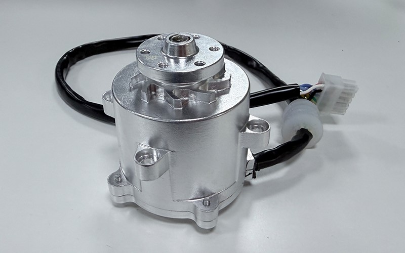
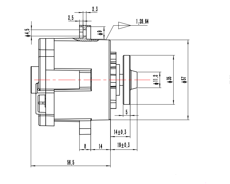
The motor that came out of this programme is the GSBLD57R90D21, a 57 mm frame, 90 W class, 21 V unit. The following values are intended for motor and drive sizing.
| Parameter | Value | Why a designer cares |
|---|---|---|
| Topology | Three-phase BLDC, inner rotor, 8 poles, 12 slots | Fixes force order at 4 and cogging at 24 per revolution |
| Rated voltage | 21 V DC | Sits mid-range in a 5-cell or 6-cell pack |
| Bus voltage range | 18–24 V DC | Sets the usable state of charge window |
| No-load speed | 5,370 rpm ±10% | Gives the back-EMF constant and the top of the speed range |
| No-load current | 1.1 A max | Bounds speed-dependent loss at the top speed |
| Rated speed | 4,500 rpm ±10% | Blade tip speed, and the frequency of every tone |
| Rated torque | 0.192 N·m | Sets the cutting load the drive can sustain |
| Rated current | 5.6 A max | Sizes the MOSFET bridge and the pack |
| Line resistance | 0.29 Ω ±10% at 25 °C | Copper loss, and the low-temperature torque limit |
| Line inductance | 0.24 mH ±5% | PWM current ripple, and therefore the switching frequency |
| Insulation | Class F, 300 V AC for 60 s, ≥10 MΩ at 250 V DC | Creepage and winding-to-frame clearance |
| Mass | 490 ± 20 g | Mounting stiffness and the mode frequencies of the deck |
| Operating range | −5 °C to +40 °C, 10–85% RH non-condensing | Outdoor duty in a European garden |
The voltage and temperature limits affect battery and enclosure design. The 18–24 V window is what makes 21 V sensible, and the trade-offs are in battery voltage selection for lawn mower motors. The −5 °C to +40 °C range is a sealing requirement as much as a thermal one, covered in waterproof motor design for lawn mowers. For a European programme the declaration route matters too: CE certified lawn mower motors for the European market.
Shaft power and end-to-end efficiency
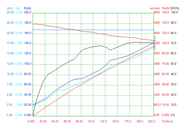
Rated torque and rated speed give shaft power directly: 0.192 × 2π × 4,500 / 60 = 90.5 W. That is where the “90” in the model number comes from, and it is a useful sanity check on any datasheet — if the two rated values do not multiply to the claimed output, one of them is wrong.
Input power at the rated point is 21 × 5.6 = 117.6 W, so end-to-end efficiency is 90.5 / 117.6 = 76.9%. That includes the controller, because the current is a DC bus current; the motor alone is higher, and the fence is drawn at the battery terminals. A motor-only figure from another supplier is a different quantity, as set out in what BLDC motor efficiency actually measures.
A loss budget from nameplate data
Total loss at the rated point is 117.6 − 90.5 = 27.1 W. Splitting it needs one assumption about commutation. In six-step 120° conduction two phases carry current at any instant, so Pcu = I² × RLL = 5.6² × 0.29 = 9.09 W, or 33.6% of the total; a sinusoidal drive conducting through all three phases would give 13.6 W. The remaining 18.0 W is iron, friction, windage, switching and stray loss, inseparable from nameplate data.
That remainder can be cross-checked, and a well-written specification survives it. A no-load current of 1.1 A at 21 V bounds all speed-dependent loss at 5,370 rpm at 23.1 W. Scaling to 4,500 rpm by (4,500 / 5,370)² = 0.702 gives at most 16.2 W against the 18.0 W residual — consistent, once you allow that 1.1 A is a maximum. Treat this as a rough cross-check: loss components do not all scale with speed squared, and the result depends on comparable current and test conditions.
| Derived quantity | Calculation | Result |
|---|---|---|
| Shaft power at rated point | 0.192 N·m × 471.2 rad/s | 90.5 W |
| DC input at rated point | 21 V × 5.6 A | 117.6 W |
| End-to-end efficiency, controller included | 90.5 / 117.6 | 76.9% |
| Total loss | 117.6 − 90.5 | 27.1 W |
| Copper loss, six-step | 5.6² × 0.29 | 9.09 W |
| Remainder, iron plus mechanical plus controller | 27.1 − 9.09 | 18.0 W |
| Electrical time constant | 0.24 mH / 0.29 Ω | 0.83 ms |
| Electrical frequency at rated speed | 4 × 4,500 / 60 | 300 Hz |
| Torque per bus ampere | 0.192 / 5.6 | 0.0343 N·m/A |
| Power density | 90.5 W / 0.490 kg | 185 W/kg |
The 0.24 mH line inductance deserves a second look. With a 21 V bus at 20 kHz, peak-to-peak ripple is roughly 21 × 0.25 / (0.24 × 10⁻³ × 20,000) = 1.09 A, about 19% of rated current. Inductance that low constrains the drive as much as the motor, which is why the controller has to be specified with the motor rather than after it.
Side by Side: When Each One Wins
Reduced to one table, the decision is less about which combination is better than about which failure mode the application can absorb. If slot and pole is one line in a longer specification, the wider process is in choosing a BLDC motor for lawn mower applications.
| Criterion | 9S10P | 12S8P | Which duty favours it |
|---|---|---|---|
| Torque per ampere | 0.945 kw1, +9% | 0.866 kw1 | 9S10P, where current is the limit |
| Cogging amplitude | Lower, 90 cycles/rev | 3.75× higher, 24 cycles/rev | 9S10P, for positioning axes |
| Lowest force order | 1, net pull | 4, self-cancelling | 12S8P, for anything noise-critical |
| Hall sensors without a ring | Not possible | Possible, 30° spacing | 12S8P, when Halls are mandatory |
| Bearing radial load | Rotating preload at 1× | Negligible | 12S8P, for life targets |
| Terminations and coils | 9 coils, fewer joints | 12 coils, more joints | 9S10P, on labour cost |
| Torque ripple at 6th order | Higher | Suppressed by coil pitch | 12S8P |
| Best overall fit | Low speed, high torque, position control | Continuous rotation, noise-critical, sensor-mandated | Depends on the load |
Two boundary cases flip the reasoning. A blade drive that must hold a fixed angular position — a tool-changer, a deck-lift actuator — is a positioning axis, and there the 9S10P’s lower cogging matters more than its force order. A drive that spins continuously at fixed speed is the opposite case, where order-4 behaviour dominates the matrix.
The known workaround for 9S10P, doubling the unit into 18 slots and 20 poles, lifts the lowest order from 1 to 2 and the cogging period to 180. It also doubles parts count and axial length, which a 57 mm blade motor cannot afford. It is a legitimate answer in a larger frame and a false economy in this one.
What 41.5 dB at 30 cm Really Means
The measured result is 41.5 dB(A) sound pressure level at 30 cm, no load, on the dedicated controller. Four words carry the meaning — sound pressure, 30 cm, no load, A-weighted — and dropping any one of them makes the number incomparable.
Sound pressure is not sound power
Sound pressure level falls with distance; sound power level does not. For a small source in free field, Lw = Lp + 20 log₁₀(r) + 11, with r in metres. Over a reflecting plane the last term becomes 8 dB. At r = 0.3 m, 20 log₁₀(0.3) = −10.5, so:
- Free field:
LwA ≈ 41.5 + 0.5 = 42.0 dB(A) - Reflecting plane:
LwA ≈ 41.5 − 2.5 = 39.0 dB(A)
The two answers differ by 3 dB, a factor of two in acoustic power, and neither is wrong: they describe different mounting conditions. Quoting one without the other is asking you to guess.
Reading it against a whole machine
Whole-machine declarations for robotic mowers are sound power levels. If a machine in this class declares 58 dB(A) LwA, a motor at 42 dB(A) LwA sits 16 dB below it — 2.5% of the acoustic power, adding about 0.1 dB. Under comparable conditions, the motor would add little to a 58 dB(A) whole-machine level. Blade, deck and airflow can dominate the complete mower’s noise.
| Metric | Depends on distance | Typical use | Comparable with 41.5 dB(A) at 30 cm |
|---|---|---|---|
| Lp at 30 cm, no load | Yes | Component-level acceptance test | This is the measurement |
| Lp at 1 m, no load | Yes | Bench comparison between motors | Approximately 10.5 dB below the 0.3 m level in free field |
| LwA, free field | No | Machine declaration, eco-design files | Yes, at approximately 42 dB(A) |
| LwA, reflecting plane | No | Machine declaration over a floor | Yes, at approximately 39 dB(A) |
| Lp at rated load | Yes | Application-realistic assessment | No, different load point |
Selection Checklist for Mower Blade Motors
Use these questions to compare candidate designs:
- Is the load a positioning axis or a continuous rotation? Positioning favours high LCM and low cogging; continuous rotation favours high GCD and low force order.
- Is Hall commutation mandatory, or is sensorless acceptable? If Halls are mandatory, check sensor spacing against slot pitch before anything else.
- What is the lowest force order of each candidate? Compute
GCD(Z, 2p). An order of 1 means a net rotating pull and a bearing preload you did not plan for. - Where does the cogging tone land at operating speed?
LCM × rpm / 60. Components between 1 and 4 kHz should be measured and assessed for amplitude; frequency alone does not predict audibility. - What is the acoustic budget of the whole machine, and how much of it is the motor? If the motor sits 10 dB or more below the machine, stop optimizing it.
- Is the noise figure a pressure level or a power level, and at what distance and load? Convert before comparing.
- Can the torque gap be recovered inside the envelope? Turns, stack length, magnet grade, slot fill — in that order of cost.
- What is the line inductance, and what switching frequency does it force? Below 0.3 mH at 20 kHz, ripple exceeds 15% of rated current.
- Does the winding have enough thermal margin at 40 °C ambient? Class F insulation is a rating, not a design temperature.
- Will the housing joints spoil the force-order advantage? End-caps and terminal boxes are acoustic radiators too, and a stiff, well-damped mounting is worth as much as a good lamination.
For a full mower programme, read custom BLDC motors for robotic lawn mowers on the specification process, performance BLDC motors for lawn mowers on what the finished article must deliver, lawn mower motor torque explained on the load side, and the RPM range that suits electric mower motors on speed. The measured programme is written up as a robotic mower blade motor case study; the wider range is at Greensky electric lawn mower motors.
References
- Yang, H., & Chen, Y. (2014). Influence of radial force harmonics with low mode number on electromagnetic vibration of PMSM. IEEE Transactions on Energy Conversion, 29(1), 38–45. https://doi.org/10.1109/TEC.2013.2290304
- Sun, T., Kim, J.-M., Lee, G.-H., Hong, J.-P., & Choi, M.-R. (2011). Effect of pole and slot combination on noise and vibration in permanent magnet synchronous motor. IEEE Transactions on Magnetics, 47(5). https://doi.org/10.1109/TMAG.2010.2093872
- Zhu, Z. Q., Xia, Z. P., Wu, L. J., & Jewell, G. W. (2010). Analytical modeling and finite-element computation of radial vibration force in fractional-slot permanent-magnet brushless machines. IEEE Transactions on Industry Applications, 46(5). https://doi.org/10.1109/TIA.2010.2058078
- Chen, Y. S., Zhu, Z. Q., & Howe, D. (2006). Vibration of PM brushless machines having a fractional number of slots per pole. IEEE Transactions on Magnetics, 42(10). https://doi.org/10.1109/TMAG.2006.879072
- Zhu, Z. Q., & Howe, D. (2000). Influence of design parameters on cogging torque in permanent magnet machines. IEEE Transactions on Energy Conversion, 15(4), 407–412. https://doi.org/10.1109/60.900501
- International Electrotechnical Commission. (2021). IEC 60034-9:2021 — Rotating electrical machines, Part 9: Noise limits. https://webstore.iec.ch/en/publication/66184
- International Electrotechnical Commission. (2014). IEC 60034-30-1:2014 — Rotating electrical machines, Part 30-1: Efficiency classes of line operated AC motors (IE code). https://webstore.iec.ch/en/publication/136
- International Electrotechnical Commission. (2014). IEC 60034-2-1:2014 — Rotating electrical machines, Part 2-1: Standard methods for determining losses and efficiency from tests. https://webstore.iec.ch/en/publication/121
- International Electrotechnical Commission. (2024). IEC 60034-2-3:2024 — Rotating electrical machines, Part 2-3: Specific test methods for determining losses and efficiency of converter-fed AC motors. https://webstore.iec.ch/en/publication/67758
- International Electrotechnical Commission. (2023). IEC 61800-9-2:2023 — Adjustable speed electrical power drive systems, Part 9-2: Ecodesign for power drive systems, motor starters, power electronics and their driven applications. https://webstore.iec.ch/en/publication/111276
- International Electrotechnical Commission. (2016). IEC TS 60034-30-2:2016 — Rotating electrical machines, Part 30-2: Efficiency classes of variable speed AC motors (IE code). https://webstore.iec.ch/en/publication/30830
- European Parliament and Council of the European Union. (2000). Directive 2000/14/EC on the approximation of the laws of the Member States relating to the noise emission in the environment by equipment for use outdoors. https://eur-lex.europa.eu/eli/dir/2000/14/oj
Frequently Asked Questions
Is a 12-slot 8-pole motor always quieter than a 9-slot 10-pole motor?
No. 12S8P removes the lowest-order net force, so it is usually quieter at the housing, but it starts with roughly 3.75 times the cogging amplitude and puts its cogging tone at 1,800 Hz, inside the ear’s most sensitive band. A 9S10P machine with shaped magnets and a damped mounting can beat a poorly executed 12S8P. Topology sets the mechanism; execution sets the number.
Can I keep a 9-slot 10-pole stator and just add a magnet ring for the Hall sensors?
Yes, and it is common. A magnet ring with its own pole pattern gives the sensors a defined field, so their 24° spacing no longer has to align with a 40° slot pitch. The costs are a second magnet component, an extra tolerance chain, axial length and a calibration step. It is reasonable when the stator is already tooled; it is rarely the answer during design.
Why does the 30° slot pitch matter so much for Hall placement?
Because 30° mechanical is exactly 120° electrical in an eight-pole machine, and 120° electrical is the spacing three Hall sensors need. The sensors therefore sit in three consecutive slot openings, and the stamped lamination defines their angular position. No sensor fixture, no magnet ring, no calibration. In a nine-slot machine the equivalent spacing is 24° against a 40° slot pitch, so the sensors cannot use the slots as a datum.
Does the higher cogging torque of 12S8P make it a bad choice for a mower blade?
It makes it a worse choice for a positioning axis, which a mower blade is not. A blade disc is a high-inertia load in continuous rotation, so cogging cannot produce a position error. What it can produce is torque ripple and a discrete tone, which is why magnets are shaped to cut cogging by 40–70% before release. Include this trade-off in the design estimate.
What does 41.5 dB at 30 cm correspond to in sound power?
About 42 dB(A) in free field and 39 dB(A) over a reflecting plane, using Lw = Lp + 20 log₁₀(r) + 11 or 8 dB at r = 0.3 m. The 3 dB spread is the mounting condition, not measurement error. Against a machine declaring 58 dB(A), a motor at 42 dB(A) contributes about 0.1 dB, which is why motor noise work stops paying.
Which combination should I choose for a 3,000 rpm blade drive?
Speed alone does not decide it. Compute GCD(Z, 2p) for the candidates, check where LCM × rpm / 60 lands, and confirm whether the sensor spacing matches the slot pitch. At 3,000 rpm the 12S8P cogging tone falls to 1,200 Hz and the 9S10P tone to 4,500 Hz, so the audibility gap widens slightly. If Hall sensors are mandatory and the envelope is tight, the arithmetic points to 12S8P regardless of speed.