
Robotic Mower Blade Motor
The cutting-disc drive had to stay under the machine’s airborne noise floor, keep Hall commutation because the controller platform already used it, and lose no shaft output. The stator went from nine slots and ten poles to twelve slots and eight. The delivered motor measures 41.5 dB(A) at 30 cm with no load.
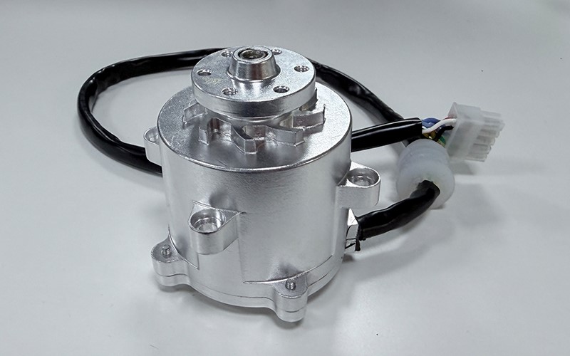
At a Glance
- Client
- European robotic mower manufacturer
- Industry
- Consumer outdoor power equipment
- Market
- Europe (EU)
- Products
- BLDC blade motor GSBLD57R90D21
- Topology
- 12-slot 8-pole FSCW, Hall-commutated
- Delivered
- 21 V · 4,500 rpm · 0.192 N·m · 490 g
- Outcome
- 41.5 dB(A) at 30 cm, no load
Customer Background
A motor buried under a mower deck, judged less by its nameplate than by what it adds to the noise and the runtime of the whole machine.
The machine is a battery-powered robotic rotary mower, and the product standard it is built against is IEC 60335-2-107, which covers robotic battery-powered electrical lawnmowers up to 75 V DC and sets the requirements for cutting-means stopping time, stability, sensors and access to hazardous parts. The blade drive is not what that standard certifies, but it is the part that fixes the machine’s noise floor, its response to load, and how much of the battery reaches the grass rather than the windings.
Two constraints shaped the programme before any electromagnetic work started. The first was acoustic: the machine is sold on how little noise it makes in a garden at seven in the morning, so the drive had to be removed as a contributor rather than merely improved. The second was architectural. The customer’s controller platform was already built around three Hall sensors, and replacing it with a sensorless design was not on the table, because that change would have cascaded into firmware, harness and qualification work across every model in the range.
The mechanical envelope was fixed as well: an existing 57 mm frame housing, a motor mass close to half a kilogram, and an 18–24 V bus shared with the rest of the platform. The project was therefore not a clean-sheet motor design. It was a stator-and-rotor redesign inside a housing that could not move, feeding a controller that could not change. Because motor and controller ship as one drive system, the ratings that apply to the combination are the drive-system conventions of IEC 61800-1, not motor-only nameplate values taken in isolation.
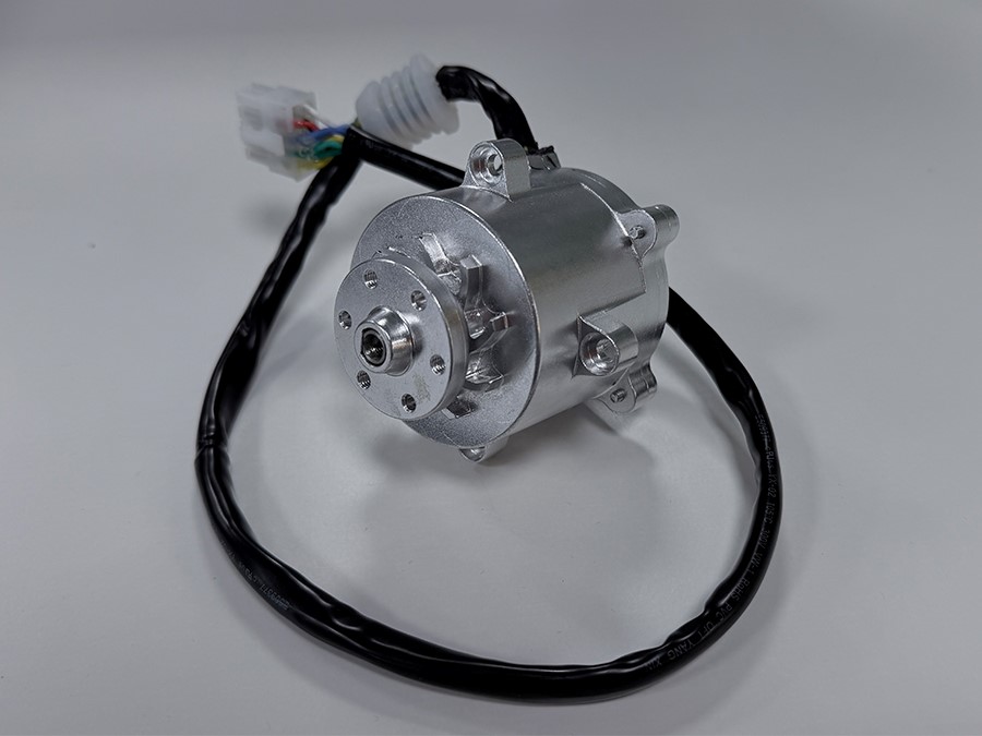
The Engineering Challenges
Four requirements, each of which translated directly into a design constraint on the slot and pole counts.
AAn acoustic target, not an acoustic wish
The brief was 43 dB(A) or lower at 30 cm with no load. The incumbent 9-slot 10-pole stator carried a lowest radial force order of one — a net rotating pull on the rotor and the housing. That is the one force shape a small housing radiates efficiently, because the whole surface moves as a single dipole and there is no neighbouring lobe to cancel against.
BHall sensors with nowhere to sit
In a nine-slot machine the sensor spacing of 120° electrical works out to 24° mechanical, while the slot pitch is 40°. Three sensors 24° apart cannot all land in slot openings, so the design would need a dedicated sensor board with its own datum, or a magnet ring. Neither fits the axial budget, and both add a calibration step to a line that runs at volume.
CNo loss of shaft output
At equal copper and magnet mass, the nine-slot ten-pole layout has a winding factor of 0.945 against 0.866 — about 9% more torque per ampere. Changing topology meant finding that 9% back inside the same housing, without spending efficiency the customer had not budgeted for.
DReproducibility at volume
Mass 490 ± 20 g. Class F insulation, 300 V AC withstand for 60 seconds, 10 MΩ minimum at 250 V DC, and an operating window of −5 °C to +40 °C at 10–85% relative humidity without condensation. A topology that only works when the sensor board is hand-aligned is not a production answer.
Products & Solution Adopted
The GSBLD57R90D21 was built around three decisions, each of which answers one of the challenges above.
12-slot 8-pole FSCW stator
Twelve slots, eight poles, one coil per tooth. The lowest radial force order becomes four instead of one, so the stator deforms in a four-lobe pattern that the lamination stack resists and that cancels acoustically at low ka.
Hall sensing without a magnet ring
Four pole pairs make one electrical cycle span 90° mechanical, so sensors 120° electrical apart sit exactly one slot pitch apart — 30°. They drop into three consecutive slot openings and the stamped lamination becomes the angular datum.
Unequal air-gap pole shaping
Twelve slots and eight poles multiply to 24 cogging cycles per revolution, roughly four times the amplitude of the incumbent. Shaped poles push the air-gap flux toward a sinusoid and cut that component before release, at a small cost in average flux.
How We Implemented It
Five stages, in the order they were run. The first stage eliminated most of the candidate combinations before any detailed design began.
Topology screen
Candidate slot and pole counts were filtered on three integers first: the greatest common divisor for force order, the least common multiple for cogging period, and the electrical angle per slot pitch for sensor feasibility. Nine slots and ten poles failed on the first and third; twelve slots and eight poles passed both.
Electromagnetic design and the 9% payback
The winding factor deficit was closed inside the fixed envelope rather than argued away. Turns, stack length, magnet grade and slot fill were each costed against the loss they add; the delivered motor settles at 0.192 N·m and 5.6 A, or 0.0343 N·m per bus ampere.
Hall geometry
Sensor positions were tied to the lamination slot openings at 30° mechanical, so the sensor spacing is defined by the same stamped part that defines the teeth. No separate fixture, no magnet ring, and no per-unit angular calibration on the line.
Pole shaping and tooling
The magnet profile was reshaped to make the air-gap flux density approach a sinusoid, targeting the 24th-order cogging component that the topology change had introduced. This is a magnet tooling change, not a lamination change.
Acoustic and thermal validation
The finished unit was measured at 41.5 dB(A) sound pressure level at 30 cm with no load, on its dedicated controller, and released against Class F insulation limits with the −5 °C to +40 °C operating window confirmed.
Requirements Met
Every figure below is either a measured value or a nameplate value on the released specification; none is a projection. The noise figure is an A-weighted sound pressure level at 30 cm, while the whole-machine declarations a buyer compares it against are sound power levels determined on an enveloping measurement surface under ISO 3744 — a different quantity, and not directly subtractable.
| Requirement | Target | Delivered | Basis | Verdict |
|---|---|---|---|---|
| Airborne noise at 30 cm, no load | ≤ 43 dB(A) | 41.5 dB(A) | Measured, dedicated controller | Met |
| Hall commutation, no magnet ring | Mandatory | 30° spacing, slot-datumed | Design geometry | Met |
| Shaft output at rated point | ≥ 90 W | 90.5 W | 0.192 N·m × 4,500 rpm | Met |
| Rated speed | 4,500 rpm ±10% | 4,500 rpm | Nameplate | Met |
| Bus voltage | 18–24 V DC | 21 V rated, 18–24 V range | Nameplate | Met |
| Pole count and topology | 8 poles, 3-phase | 12-slot 8-pole FSCW | Nameplate | Met |
| Mass | ≤ 500 g | 490 ± 20 g | Nameplate | Met |
| Insulation | Class F, 300 V AC / 60 s, ≥ 10 MΩ | Class F, 300 V AC / 60 s, ≥ 10 MΩ at 250 V DC | Nameplate, routine test | Met |
Why This Topology Suits Mower Duty
Four reasons, in order of how much they contributed to the result.
1Force order, not frequency
The usual justification — that twelve slots run at a higher frequency and push noise above the audible band — does not survive arithmetic. At 4,500 rpm the twelve-slot machine runs at 300 Hz and the nine-slot at 375 Hz. What changes is the mode order: at the housing’s ka of about 0.36, order-4 surface motion radiates roughly 26 dB less efficiently than order-1 motion at equal displacement, because adjacent lobes cancel.
2The lamination is the sensor datum
A 30° sensor spacing that lands on a 30° slot pitch is not a convenience, it is a tolerance decision. The angular relationship between the three sensors is fixed by one stamped part, so drift in the sensor board cannot open a commutation error. That is what made Hall commutation compatible with a fixed envelope and a volume line.
3The cogging cost is real, and priced
Twelve slots and eight poles give 24 cogging cycles per revolution against 90, and in first-order terms roughly 3.75 times the amplitude. That tone lands at 1,800 Hz, inside the band where hearing is most sensitive. It was acceptable only because the load is a high-inertia disc in continuous rotation, where cogging cannot cause position error — and because the magnets were shaped to cut the component before release.
4Twelve coils, not nine
The honest disadvantage. Twelve teeth mean twelve coils and more terminations, and the winding factor is lower. Both were accepted because the alternative carried a bearing preload from an order-1 force and a sensor architecture that did not fit. The trade is documented rather than hidden, which is the only way a customer can repeat the decision on their own platform.
What the Programme Delivered
Outcome, stated without attribution
- The motor was removed as a constraint on the machine’s acoustic budget: at 16 dB below a typical whole-machine declaration for this class, it contributes roughly 0.1 dB to the total. Further work on the motor would not be measurable.
- Hall commutation was retained on the existing controller platform with no magnet ring and no per-unit angular calibration, so no firmware, harness or qualification change was required on the customer’s side.
- The 9% winding-factor deficit was recovered inside the fixed 57 mm envelope, ending at 0.192 N·m and 90.5 W shaft output at 4,500 rpm and 490 g.
Customer identity is withheld at their request. No quotation is reproduced here.
Specifying a blade motor for a robotic mower?
Send the envelope, the bus voltage, the noise target and whether Hall commutation is mandatory. We will come back with the slot and pole candidates that survive all three, and the force order and cogging period for each.
Start Your Application Case
Share your envelope, noise target with its measurement conditions, bus voltage and duty cycle — our engineers respond within 24 hours with a tailored motor proposal.
Greensky Power Co., Ltd.
Email: mkt@greensky-power.com
Tel: +86 5718819 5488
Customized Service: Yes
Related: Custom BLDC motors for robotic lawn mowers · 9S10P vs 12S8P slot–pole comparison