
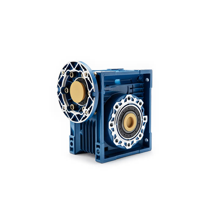
What Is a Worm Gear Reducer?
Quick Answer
What Is a Worm Gear Reducer?
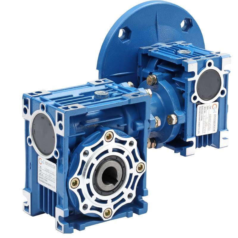
A worm gear reducer is a housed power-transmission unit that steps a motor’s speed down and its torque up through a crossed-axis worm-and-wheel mesh. Unlike spur, helical, or planetary sets whose shafts are parallel or intersect, the worm and wheel run on perpendicular, non-intersecting axes — that is what gives the characteristic 90° right-angle output in one compact package.
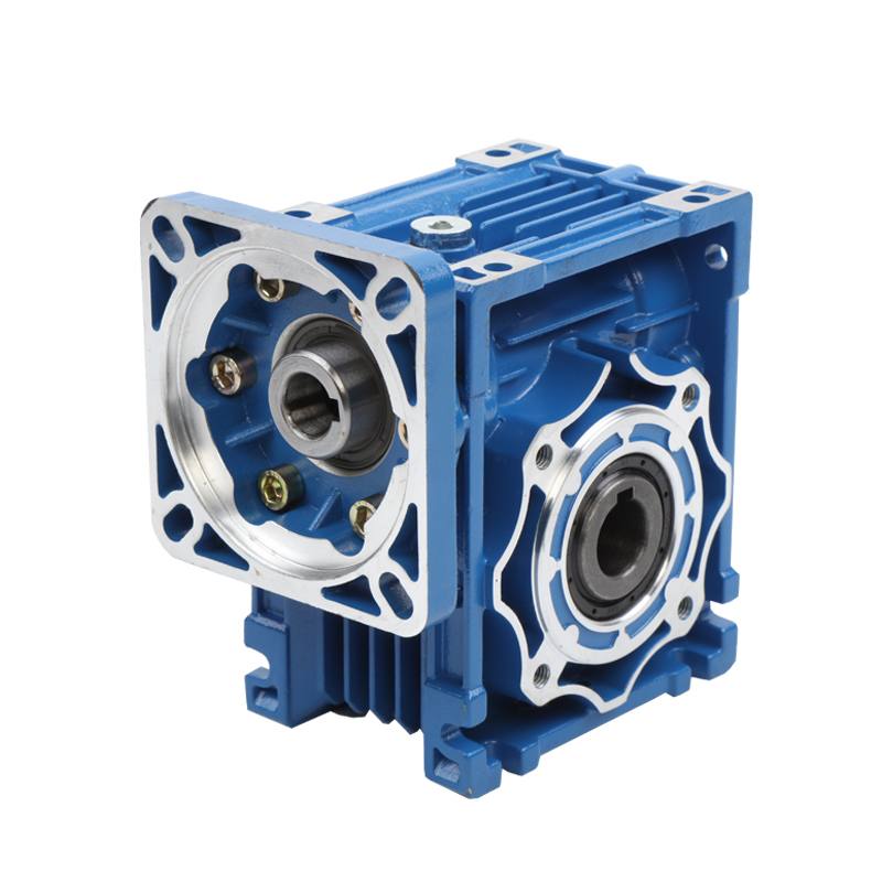
The assembly has five functional parts:
- Worm (input): a shaft cut with a helical/screw thread, usually hardened alloy steel (e.g., 20CrMnTi carburized to HRC 58–62).
- Worm wheel (output): the toothed wheel that meshes with the worm, almost always centrifugally cast tin bronze (CuSn12 / ZCuSn10Pb1) for wear resistance against the steel worm.
- Housing: aluminum alloy (NMRV-style) or cast iron, carrying the bearings and the oil bath; finned walls shed heat.
- Bearings & seals: support the shafts and retain lubricant while blocking contaminant ingress (IP55/IP65 typical).
- Lubrication bath: an oil sump that the wheel (or a dedicated splash gear) dips into.
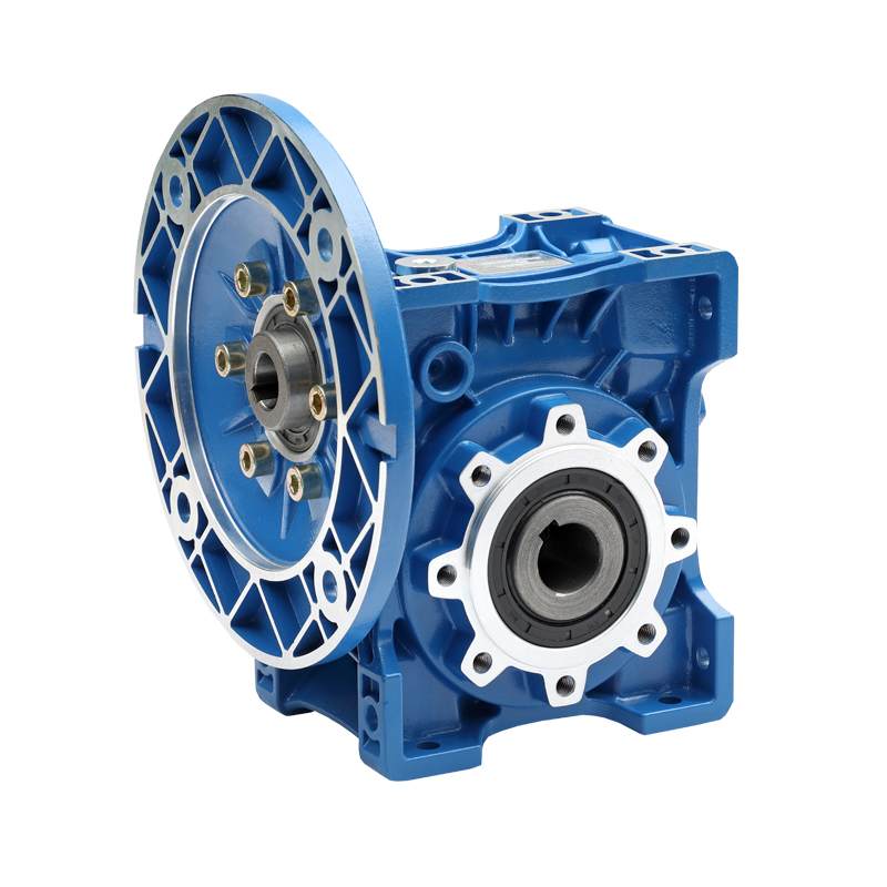
Because the wheel is small in diameter relative to the box, a worm reducer is one of the slimmest reducers available — a property the original Greensky page already flagged as its main space-saving advantage. The deeper gear-mesh theory, tooth geometry, and manufacturing detail belong in our companion complete guide to worm gears.
How a Worm Gear Reducer Works — Step by Step
- Motor drives the worm. The input shaft spins the helical worm at motor speed (e.g., 1,400 rpm for a 50 Hz 4-pole motor).
- Thread engages the wheel. Each turn of the worm advances the wheel by one (or more, for multi-start worms) tooth/thread pitch — like a screw driving a nut.
- Motion transfers at 90°. Because the axes are perpendicular and offset, the output rotation leaves the box at a right angle to the input.
- Reduction is set by tooth count. The ratio is i = Ng / Nw, where Ng is wheel teeth and Nw is worm starts. A 1-start worm on a 30-tooth wheel = 30:1.
- Contact is sliding, not rolling. The worm thread wipes across the wheel tooth, which is why running is smooth and quiet but friction — and heat — are inherent.
- Self-locking emerges at low lead angles. If the worm lead angle λ is smaller than the mesh friction angle φ = arctan(μ), the wheel cannot drive the worm backward. This is what lets a hoist hold load without a brake.
The mechanism is positive (no slip), reversible in the forward direction, and capable of very high single-stage ratios that would need two or three stages in a helical or planetary train.
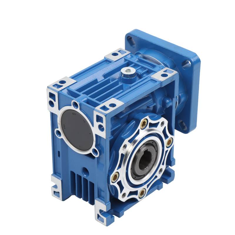
Worm Gear Reducer vs. Other Reducer Types
The table below is the fastest way to see where a worm drive wins and where it loses. Full efficiency alternatives are covered in our gearbox vs. gear-motor and harmonic vs. planetary comparisons.
| Feature | Worm gear reducer | Helical gear reducer | Planetary reducer | Bevel gear reducer |
|---|---|---|---|---|
| Single-stage ratio | 5:1 – 300:1 | 3:1 – 100:1 | 3:1 – 1000:1 (multi-stage) | 1:1 – 6:1 |
| Efficiency | 40% – 92% | 95% – 98% | 85% – 97% | 95% – 98% |
| Self-locking | Yes (high ratio) | No | No | No |
| Backlash (standard) | 15–30 arc-min | 5–20 arc-min | 3–15 arc-min | 5–15 arc-min |
| Noise | Very low | Moderate | Low | Moderate |
| Relative cost index | 1.0× | 1.2–1.5× | 1.5–2.0× | 1.2–1.4× |
| Best fit | Right-angle, high ratio, holding | High-efficiency continuous duty | High torque density, servo | Right-angle, low ratio, efficient |
Engineering Data: Efficiency, Self-Locking & Torque
Efficiency formula
The defining equation for a worm stage is:
η = tan(λ) / tan(λ + φ), where φ = arctan(μ)
λ = worm lead angle, μ = coefficient of friction at the mesh (bronze/steel with EP worm oil is typically 0.04–0.12), φ = friction angle.
Worked check from a real online calculator: a 1-start worm on a 40-tooth wheel with λ = 5° and μ = 0.12 gives φ = arctan(0.12) = 6.84°, so η = tan 5° / tan 11.84° = 0.0875 / 0.2097 ≈ 41.7%. That is why a self-locking 40:1 box throws away the majority of its input power as heat.
Self-locking condition
Self-locking occurs when φ > λ (friction angle exceeds lead angle). With μ = 0.12, φ ≈ 6.8°, so any worm with a lead angle below about 6.8° self-locks. High-ratio single-start worms qualify; low-ratio multi-start worms do not.
Efficiency vs. ratio (representative, single stage)
| Ratio (i) | Typical worm starts | Efficiency η | Self-locking? |
|---|---|---|---|
| 5:1 | 4-start | 89% – 93% | No |
| 10:1 | 2-start | ≈ 85% | No |
| 20:1 | 2-start | ≈ 78% | No |
| 30:1 | 1-start | ≈ 70% | Borderline |
| 40:1 | 1-start | ≈ 60% | Yes |
| 60:1 | 1-start | ≈ 50% | Yes |
| 100:1 | 1-start | ≈ 45% | Yes |
Torque and power
Output torque is the motor torque multiplied by ratio and efficiency:
Tout = Tin × i × η
Power lost as heat = Pin × (1 − η). At a 40:1 self-locking box running at 41.7% efficiency, nearly 60% of motor power becomes heat — the single most important constraint for continuous duty.
Temperature and thermal limits
- Standard oil-sump operating temperature: 80–90°C continuous.
- High-temperature builds (special grease/oil): up to 120°C intermittent.
- Continuous-duty thermal rating follows AGMA enclosed-drive practice — size to the thermal limit, not just peak torque.
Worked Selection Example (the part most catalogs skip)
Scenario: a horizontal conveyor needs 120 N·m continuous at the output shaft turning at 60 rpm. We pair it with a 50 Hz 3-phase motor.
| Step | Calculation | Result |
|---|---|---|
| 1. Pick motor | Standard frame, 1.1 kW at 1,400 rpm | — |
| 2. Motor torque | Tin = 9550 × P / n = 9550 × 1.1 / 1400 | 7.50 N·m |
| 3. Required ratio | i = 1400 / 60 | 23.3:1 → select 25:1 |
| 4. Gross output torque | 7.50 × 25 | 187.5 N·m |
| 5. Apply efficiency | 25:1, double-start, η ≈ 0.85 | 187.5 × 0.85 = 159 N·m |
| 6. Check margin | 159 vs. required 120 | 33% margin — OK |
| 7. Heat load | Ploss = 1.1 × (1 − 0.85) | 0.165 kW = 165 W |
Counter-intuitive insight: had we specified a single-start self-locking 25:1 worm (η ≈ 0.80), output would still clear 120 N·m (150 N·m) — but heat rises to 220 W and the box runs hotter for no benefit, because a conveyor never needs to hold position against back-drive. Choosing the double-start high-efficiency worm gives the same torque with 25% less heat. Self-locking and high efficiency are mutually exclusive in one worm stage; you pay for holding ability in wasted watts.
Notice step 5 multiplies by efficiency after the ratio. Undersizing happens when engineers size Tout = Tin × i and forget η, then wonder why the conveyor stalls.
Best Applications for a Worm Gear Reducer
| Application | Why a worm drive fits | Notes |
|---|---|---|
| Conveyors & material handling | Right-angle, compact, quiet | Use high-efficiency multi-start worm |
| Hoists, cranes, lifts | Self-locking holds load | Single-start, ratio ≥ 30:1; add a real brake for safety |
| Gate & door openers, security barriers | Self-locking + low speed | Common in the Greensky NMRV worm gearbox range |
| Mixers & agitators | High torque at low rpm | Watch thermal rise in continuous duty |
| Packaging & automation | Smooth, low-backlash options | Precision units < 10 arc-min |
| Solar trackers & valve actuators | Hold position without power | Self-locking is the key feature |
| Medical & instrument positioning | Quiet, fine incremental motion | Pair with a stepper motor for indexing |
For battery- or efficiency-critical motion where a worm’s losses are unacceptable, our BLDC motors with planetary gearboxes are the usual alternative. Troubleshooting of the gear mesh itself is detailed in our micro motor gear reducer problems guide.
Step-by-Step Worm Gear Reducer Selection
- Define the load. Required output torque (N·m), speed (rpm), duty cycle, and whether the load can back-drive.
- Choose motor power. P(kW) ≈ Tout × nout / (9550 × η); always include η and a service factor.
- Set the ratio. i = nmotor / nout; round to a standard ratio (5, 10, 15, 20, 25, 30, 40, 50, 60, 100).
- Decide self-locking. If the load must hold without power/brake → single-start high ratio. If efficiency matters → multi-start.
- Apply service factor. AGMA factors cover shock, hours/day, and ambient — a 1.5× factor is common for irregular industrial loads.
- Check the thermal limit. Confirm the housing can shed Ploss at continuous duty; upsize ratio/efficiency or add cooling if not.
- Pick mounting & seal level. Foot, flange (B5/B14), or shaft; IP55 standard, IP65/IP66 for washdown or dust.
Common Engineering Mistakes
- Sizing torque before efficiency. Tout = Tin × i × η, not Tin × i. The example above shows a 0.75 kW motor failing where 1.1 kW succeeds.
- Using the wrong oil. Standard engine or spur-gear oil lacks EP additives and scuffs the bronze wheel. Use ISO VG220/320 worm oil.
- Ignoring continuous-duty heat. A self-locking 40:1 box at 1.1 kW dumps ~220 W as heat. Sizing to peak torque alone cooks the unit.
- Treating self-locking as a safety brake. Hot oil lowers μ and defeats borderline self-locking. Always add a redundant mechanical brake on lifts.
- Assuming low backlash. Standard worm boxes run 15–30 arc-min; precision positioning needs a preloaded anti-backlash or planetary unit.
- Expecting back-drive. A self-locking reducer will not let the load spin the input — design the drive direction accordingly.
- Misalignment & over-tightening. Shaft misalignment and crushed seals are leading causes of early oil leaks and bearing failure.
- Skipping the first oil change. Run-in wear particles should be flushed at ~400 hours, not left circulating for 4,000 hours.
Troubleshooting: Problem → Cause → Solution
| Problem | Likely cause | Solution |
|---|---|---|
| Overheating (> 90°C sump) | Undersized efficiency, wrong oil, overloaded duty | Recheck Tout calc, use correct VG oil, add cooling or upsize ratio |
| Oil leakage at seals | Overfill, worn lip seal, misalignment, housing porosity | Set correct oil level, replace seals, realign shafts |
| Abnormal noise / vibration | Bearing wear, misalignment, insufficient lubrication | Inspect bearings, align, top up oil |
| Excessive backlash | Wheel tooth wear, bearing clearance | Replace wheel/bearings; use anti-backlash for precision |
| Worm wheel scoring/wear | Wrong lubricant, contamination, poor material pair | Switch to EP worm oil, clean system, verify bronze grade |
| Loss of self-locking | Hot oil lowered μ, worn mesh | Add mechanical brake; do not rely on self-locking at temperature |
| Bearing failure | Contamination, misalignment, overload | Replace bearings, reseal, verify load & alignment |
Frequently Asked Questions
What is the difference between a worm gear reducer and a worm gear?
A worm gear is the gear pair itself: the screw-shaped worm and the toothed worm wheel. A worm gear reducer (worm gearbox) is the complete, housed power-transmission unit that contains the worm and wheel plus bearings, seals, a lubrication bath, and a mounting interface for a motor. Spec sheets that say “worm gear” usually mean just the pair; “reducer” or “gearbox” means the assembled drive.
Are worm gear reducers self-locking?
They can be, but not always. Self-locking occurs when the worm lead angle is smaller than the mesh friction angle (λ < φ = arctan μ). This happens reliably at high single-stage ratios — roughly 30:1 and above with a single-start worm — where lead angles drop below about 6°. Low-ratio multi-start worms (10:1 or less) have large lead angles, run at 85–92% efficiency, and will back-drive. Also note: hot oil lowers friction and can defeat borderline self-locking, so never treat it as the sole safety brake on a lift.
What efficiency can I expect from a worm gear reducer?
Efficiency depends on ratio and worm starts. Representative single-stage values: 5:1 ≈ 89–93%, 10:1 ≈ 85%, 20:1 ≈ 78%, 30:1 ≈ 70% (borderline self-locking), 40:1 ≈ 60% (self-locking), 60:1 ≈ 50%, 100:1 ≈ 45%. The formula is η = tan(λ) / tan(λ + φ). The trade-off is direct: the more reduction you want from one stage, the more input power you lose as heat.
When should I avoid a worm gear reducer?
Avoid worm drives for high-speed, continuous-duty, or efficiency-critical motion where sliding losses become a thermal and energy penalty (use helical or planetary instead). Also avoid them where the load must back-drive the input, and where you need very low backlash for precision positioning — a standard worm box runs 15–30 arc-min of backlash versus 3–10 for a precision planetary.
What lubrication do worm gear reducers need?
Use a dedicated extreme-pressure worm-gear oil — typically ISO VG220 (PAO synthetic) as standard, VG320 for high-cycle reversing duty, and PAG for high-temperature operation. Ordinary engine oil or spur-gear oil lacks the EP additives and causes scuffing of the bronze wheel. Change the oil after the first ~400 hours of run-in, then about every 4,000 hours.
How long do worm gear reducers last?
With correct lubrication and load, the bronze worm wheel typically lasts 6–10 years of continuous service before replacement; the hardened-steel worm usually outlasts several wheels. In practice, bearing, seal, and oil-cleanliness condition dominate the service interval — overheating and contamination end most boxes long before tooth fatigue does.
Why Choose Greensky for Worm Gear Reducers & Custom Drives?
When a standard catalog worm reducer fits, the big brands are fine. When you need a motor + worm-gear reducer as one engineered assembly, a custom center distance or ratio, or flexible volumes, Greensky Power is the OEM/ODM partner. Since 2011 we have built worm-gear reducers (NMRV / WP series), BLDC, brushed DC, and stepper motors with matched gearheads for customers in 50+ countries.
- Integrated drivetrains: motor + worm reducer supplied as one concentric assembly — no adapter guesswork, correct flange every time (IEC B5/B14 or NEMA C-face).
- Custom ratios & center distances: tailored reduction, self-locking or high-efficiency (multi-start) builds to your load profile.
- Thermal-aware sizing: we size to the AGMA continuous-duty thermal limit, not just peak torque, so your unit does not cook in continuous operation.
- Flexible MOQ & lead time: from prototype to mass production.
- Standards practice: designed to IEC 60034 / NEMA MG 1 motor practice; ISO and CE certified.
- Local support: engineering help through our North America & Europe channels.
References
- AGMA 6034-B92 (ANSI/AGMA 6034), Practice for Enclosed Worm Gear Speed Reducers and Gearmotors. https://www.agma.org/standards/
- ISO 14521, Worm-gear pairs — Calculation of load capacity. https://www.iso.org/standard/54551.html
- IEC 60034-1, Rotating electrical machines — Rating and performance. https://webstore.iec.ch/publication/60034-1
- NEMA MG 1, Motors and Generators. https://www.nema.org/standards/view/motors-and-generators
- SKF, Bearing rating life (L10), mounting & lubrication guidance. https://www.skf.com/group/support/engineering-tools/bearing-calculator
- Siemens / Flender, Gear unit engineering — worm gear drive technology. https://www.siemens.com/global/en/products/automation/drive-technology/gear-units.html
- IEEE Standard 112, Test Procedure for Polyphase Induction Motors and Generators. https://standards.ieee.org/ieee/112/4703/
- U.S. Department of Energy, Motor & Drive Systems — Energy Efficiency. https://www.energy.gov/eere/motors
- Cone Drive (Regal Rexnord), Double-enveloping (Envex®) worm gear technology. https://www.conedrive.com/technology/
- maxon, Gearheads — selection and matching to DC/BLDC motors (manufacturer technical guide). https://www.maxongroup.com/
- ISO 6336, Calculation of load capacity of cylindrical gears (strength context). https://www.iso.org/standard/76425.html
- Boston Gear / Regal Rexnord, Worm gearbox engineering catalog & selection. https://www.regalrexnord.com/brands/boston-gear
