

Vacuum Cleaner Motors: Air Power at the Operating Point
Quick Answer
A vacuum cleaner motor is not rated by watts or by pascals. It is rated by one point on a fan curve, and the only figure that compares two machines is air power: airflow multiplied by pressure difference, measured at the point where the machine actually runs. Peak airflow and peak suction are the two ends of that curve, and air power is zero at both, because at either end one of the two factors disappears. Multiplying the two extremes produces a number no operating point can reach. A 5.7-inch thru-flow motor catalogued at 130 CFM and 93 inches of water yields 1,429 air watts by that multiplication and about 435 W in reality. Size at the duty point.
- Air power is a product, and both endpoints are zero
- The fan curve is the real specification
- Three motor families and where each one lives
- Where the other two thirds of the watts go
- Voltage, speed and the cubic law
- Brush life, bearing life and the 500-hour rule
- A sizing sequence with a complete example
- What the standards actually require
- Matching the motor to the machine
- Six mistakes that reach production
- Troubleshooting: symptom, cause, action
- How Greensky Power builds vacuum motors
- References
- FAQ
Air Power Is a Product, and Both Endpoints Are Zero
A vacuum cleaner does not pull. It creates a pressure difference, and the atmosphere pushes air through the machine because of it. That distinction decides how the motor has to be specified, because a pressure difference with no flow moves no dust, and flow with no pressure difference cannot lift a particle off a carpet fibre. Cleaning happens where both exist at once.
The quantity that combines them is air power. In SI units it is simply pressure in pascals multiplied by volumetric flow in cubic metres per second, which gives watts. The imperial version used across the American vacuum industry multiplies airflow in cubic feet per minute by suction in inches of water and divides by 8.5. That divisor is not a physical constant; it is a unit conversion. Converting a published point both ways shows the two methods agree to within a tenth of a percent, so anyone claiming the constant carries a safety factor is misreading it [1].
| Figure on the box | What it actually measures | What it hides |
|---|---|---|
| Sealed suction in Pa or inches of water | Pressure difference with the inlet blocked | Flow, which is zero at that condition |
| Maximum airflow in CFM or litres per second | Volume moved with the inlet fully open | Pressure, which is zero at that condition |
| Input watts | Electrical power drawn at the plug | Everything between the plug and the air |
| Air watts | Pressure times flow at a stated point | Nothing, provided the point is stated |
Water lift is a floor, not a rating
Sealed suction has one legitimate use: it is the highest pressure the machine can build, so it sets the depth from which the machine can theoretically lift material in a vertical tube. It is a floor value. The same is true at the other end, where maximum airflow tells you how much air the machine can move through a wide open nozzle and therefore how well it will collect light debris from a hard floor. Neither number describes a working machine.
This is why a marketing figure in the tens of thousands of pascals, quoted alone, carries almost no information. Two machines can both claim 20 kPa, and one can move three times the air of the other at that pressure. The pressure figure does not distinguish them, and the flow figure is not shown. Measuring the performance of a dry vacuum cleaner properly requires both, under controlled conditions, which is exactly what IEC 62885-2 sets out [2].
The Fan Curve Is the Real Specification
A fan running at a fixed speed traces a curve when pressure is plotted against flow. It starts at the sealed point on the pressure axis, where flow is zero, and falls to the open point on the flow axis, where pressure is zero. The motor’s own capability crosses this curve, and the machine’s ducting adds a second curve that rises with flow because pressure loss grows roughly with the square of velocity. The intersection of the fan curve and the system curve is the operating point. That point, and nothing else, determines what the user experiences.
The multiplication that nobody can reach
One published datasheet for a 5.7-inch single-stage thru-flow motor gives 130.5 CFM of maximum airflow and 93.1 inches of water of sealed suction, at 34,250 rpm and 10.4 A on 120 V. The datasheet also states the maximum air watts as about 435 W.
The multiplication gives 130.5 times 93.1 divided by 8.5, which is 1,429 air watts. The catalogue says 435 W. The multiplication overstates the motor by a factor of 3.29, and the reason is structural rather than a rounding error: at maximum airflow the pressure is zero, and at maximum pressure the flow is zero, so the product is zero at both ends and peaks somewhere in between.
| Motor | Max airflow | Sealed suction | Extremes multiplied | Rated max air watts | Overstatement |
|---|---|---|---|---|---|
| 5.7 in single-stage thru-flow, 120 V, 10.4 A | 130.5 CFM (0.0616 m3/s) | 93.1 in H2O (23.2 kPa) | 1,429 W | 435 W | 3.29x |
| Bypass motor, 1,800 W, 34,000 rpm | 3.2 m3/min (0.0533 m3/s) | 34 kPa | 1,813 W | 540 W | 3.36x |
Two datasheets from different motor designs, one thru-flow and one bypass, one imperial and one metric, land on the same overstatement factor within two percent. The agreement reflects the shape a single-stage centrifugal fan has to take, which makes the trap systematic: any brochure quoting a flow and a pressure side by side invites the reader to perform a multiplication that is wrong by a factor of three.
Where peak air power actually sits
If the fan curve were a straight line between the two endpoints, air power would peak exactly halfway along it, at half the open flow and half the sealed pressure. Working that out for the same motor gives 0.0308 cubic metres per second times 11.6 kPa, which is 357 W. The datasheet says 435 W. The real curve therefore bows outward: the fan holds more pressure than a straight line at mid flow, which is what a well-matched impeller and diffuser are for. A designer who wants air watts at a working point should ask for the curve, not the two ends, and should expect the peak near half of open flow, nowhere near either extreme.
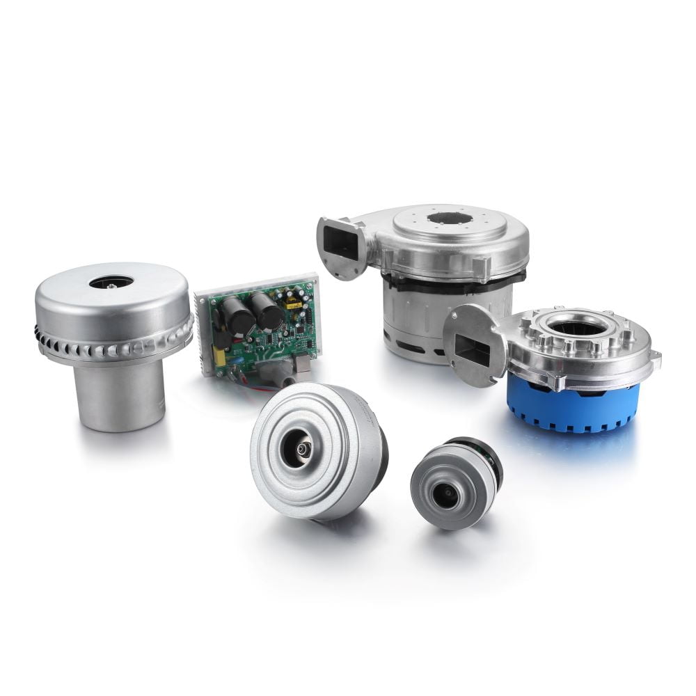
Three Motor Families and Where Each One Lives
Vacuum motors are often grouped by supply, as AC, DC or brushless, and that grouping says more about the electronics than about the duty. A more useful split is by how each family gets its air power and what that costs.
The universal motor is a series motor
Nearly every corded vacuum cleaner uses a universal motor: a wound rotor and a wound stator connected in series, fed through a commutator and carbon brushes. Because the field and the armature are in series, the machine produces high torque at low speed and runs fast at light load, which suits a centrifugal fan almost perfectly. It also runs on AC or DC without modification, hence the name. Standard designs now turn at 30,000 to 40,000 rpm, and some exceed 50,000 rpm, which is what allows a small impeller to generate serious pressure [10][11].
The cost is the commutator. Brushes wear, sparking limits electromagnetic compatibility, and the maximum life is set by brush grade and by how well the manufacturer keeps dust out of the brush boxes. Nothing about the family has changed in decades; what has changed is the speed and the detail quality.
| Property | Universal (brushed) | Brushless DC with inverter | Induction with bypass fan |
|---|---|---|---|
| Typical speed | 30,000 to 50,000 rpm | 60,000 to 120,000 rpm | 2,000 to 3,600 rpm |
| Supply | AC or DC, mains fed | Battery or DC bus | AC mains or three-phase |
| Air power efficiency | About 30 to 35 percent | Roughly 40 percent and up | Lower, but not speed limited |
| Life limit set by | Brush and commutator wear | Bearings and electronics | Bearings and insulation |
| Control | Triac phase angle, crude | Field oriented, precise | Fixed speed, or a VFD |
| Where it is used | Canister, upright, wet and dry | Stick, handheld, cordless | Central, industrial, wet and dry |
A common claim, and a wrong one: that a low-speed motor produces more torque and is therefore better for heavy-duty cleaning. Torque is not the output a vacuum cleaner sells. Air power is, and it is available from either a small impeller at high speed or a large impeller at low speed. Reaching the same air power at 3,000 rpm instead of 34,000 rpm needs an impeller roughly eleven times the diameter, and industrial units are large for exactly that reason.
The choice between the families is therefore about life, cost and cooling path, not about which one has more torque. For the brushless comparison in more depth, see BLDC versus induction motor and the disadvantages of brushless DC motors.
Where the Other Two Thirds of the Watts Go
Air power divided by input power gives the number that matters more than any other here. For the 5.7-inch motor above, 435 W of air power against 120 V times 10.4 A, which is 1,248 W, gives 34.9 percent. For the 1,800 W bypass motor, 540 W of air power gives 30.0 percent, and its own datasheet states a maximum suction efficiency of 33 percent. The two machines and the two measurement systems land on the same answer: roughly a third of the electricity becomes air movement.
Two efficiencies get confused at this point, and the confusion produces specifications that cannot both be true. The 65 to 75 percent figure that appears on many supplier pages is the electrical efficiency of the motor and its controller, measured at the shaft. The 30 to 35 percent figure here is air power over input power, measured in the airstream. Both can be correct at once, because the fan stage sits between them and a centrifugal fan at this pressure ratio converts a little under half of shaft power into air power. A datasheet that quotes the higher number while claiming it describes suction performance is describing the wrong end of the machine.
The 65 percent that cools the winding
The remaining two thirds do not vanish. They become heat, and in a thru-flow motor that heat enters the airstream that has just left the fan. The temperature rise can be calculated directly: divide the loss by the product of air density, specific heat and volumetric flow. At 813 W of loss and 0.0616 cubic metres per second, using 1.2 kilograms per cubic metre and 1,005 joules per kilogram-kelvin, the rise is 10.9 K.
That number explains the thru-flow architecture. The motor is not wasting two thirds of its input; it is using the exhaust as a coolant. It also explains why the same architecture fails so specifically, because the cooling is proportional to flow and flow is the first thing a blockage removes.
Sealed suction is not a duty point
Applied down the flow range, the same arithmetic turns the failure mode into a curve.
| Airflow through the motor | Air temperature rise | What it means in service |
|---|---|---|
| 0.0616 m3/s (open, clean filter) | 10.9 K | Normal running, winding well inside its class |
| 0.045 m3/s (hose and wand fitted) | 15.0 K | Typical working condition |
| 0.020 m3/s (half-blocked filter) | 33.7 K | Winding rise plus this, margin shrinking |
| 0.010 m3/s (blocked filter) | 67.4 K | Insulation life collapsing |
| 0.005 m3/s (near sealed) | 134.8 K | Failure in minutes, not hours |
Never run a thru-flow machine at sealed suction as a life test. The sealed condition is a measurement point used for a few seconds to read maximum pressure, not an operating condition. At sealed suction the cooling flow is zero while the motor is still drawing close to full current, so the winding has no way to shed its losses. Any test rig that holds the inlet closed to check a motor will destroy a good motor and attribute the failure to the wrong cause.
A bypass motor breaks this coupling. A second fan, driven from the same shaft, draws clean ambient air across the armature and field and discharges it separately, so the working air never touches the winding. Wet and dry and central units use the arrangement for that reason, and it is also why they are bigger and noisier: there are now two airstreams to route and two fan systems to balance.
Voltage, Speed and the Cubic Law
Because a universal motor is not synchronous with the supply, line frequency has almost no effect on its speed. A 50 Hz machine and a 60 Hz machine at the same voltage turn at nearly the same rpm. This matters because a great deal of imported equipment arrives with assumptions borrowed from induction motors, where a 20 percent frequency increase really does mean a 20 percent speed increase. Applying that logic to a vacuum motor produces a redesign that was never needed.
Voltage is the variable that matters, and it enters three times. Fan laws state that flow scales with speed, pressure with the square of speed, and air power with the cube. Since the speed of a series motor at fixed load is roughly proportional to applied voltage, air power follows the cube of voltage.
| Supply voltage | Relative speed and flow | Relative pressure | Relative air power | Loss against 230 V |
|---|---|---|---|---|
| 230 V | 1.000 | 1.000 | 1.000 | 0 percent |
| 220 V | 0.957 | 0.915 | 0.875 | 12.5 percent |
| 208 V | 0.904 | 0.818 | 0.740 | 26.0 percent |
A 208 V site supply is common in North America and in some export installations, and it costs a nominal 230 V machine a quarter of its air power before anything is even connected to the hose. The same arithmetic applies to a long extension lead: ten percent of voltage drop costs about 27 percent of suction. A machine that performs well on a bench can therefore disappoint at the far end of a workshop. The measurement that settles the question is a running voltage reading at the motor terminals, not a nameplate check.
A brushless machine with closed-loop speed control behaves differently: it holds speed and takes more current instead, so the loss appears as heat and as a shorter battery runtime rather than as weaker suction. That is a genuine advantage, and it is also why cordless runtime tables cannot be read as suction comparisons. The speed and efficiency fundamentals are set out in brushless DC motor technology.
Brush Life, Bearing Life and the 500-Hour Rule
Nothing on a vacuum motor works slowly. At 34,250 rpm the shaft turns 571 times a second, so a twelve-segment commutator presents a fresh segment to each brush about 6,850 times a second, or once every 146 microseconds. Brush grade, spring pressure and commutator film all have to be right at that rate. A vacuum motor is not simply a small universal motor with a fan bolted on.
A brush at 571 revolutions per second
Brush life in this class is normally quoted between 500 and 1,500 hours, and the difference between the two ends is metallurgy and dust exclusion rather than size. The EU ecodesign regulation requires an operational motor lifetime of at least 500 hours for corded household machines, and IEC 62885-2 defines the test that establishes it, alongside the method for rated input power [2][8].
Five hundred hours sounds generous until it is divided by a duty cycle. At one hour a week in a house it is about nine and a half years. At five hours a day in a contract cleaning round it is a hundred working days. The same motor, the same test certificate, two completely different outcomes, and the certificate tells the buyer nothing about which one they are getting.
| Failure mode | What sets the limit | Practical countermeasure |
|---|---|---|
| Brush and commutator wear | Current density, spring force, dust ingress | Higher grade brush, sealed brush boxes, filter integrity |
| Bearing life | dn value, preload, grease, balance | Preloaded ball bearings, controlled balance grade |
| Winding insulation | Temperature rise against insulation class | Keep the cooling path clear, respect duty cycle |
| Fan erosion | Abrasive dust at impeller tip speed | Upstream filtration, harder impeller material |
The fourth row in that table is the one buyers overlook. Tip speed at the impeller rim is the same arithmetic as any centrifugal fan, and at 34,000 rpm a 90 mm impeller runs close to 160 m/s, so abrasive dust erodes the blade tips and widens the running clearance. Air power falls away gradually and the symptom is reported as “the motor is getting weak” long after the cause was mechanical. Impeller material selection is covered in metal or plastic fan for an electric motor.
The bearing is a dn-value problem
Bearing selection at these speeds is governed by the bore diameter multiplied by rotational speed. An 8 mm bore running at 34,250 rpm gives a dn value of about 274,000, which is inside the range grease-lubricated instrument bearings can hold but with little margin for a poor grease or a wrong preload. Balance matters at the same time, because unbalance force rises with the square of speed; the evaluation and limits for machine vibration are set out in IEC 60034-14, and they matter more here than on a 1,500 rpm industrial motor [6].
Both of these sit underneath the more visible question of enclosure protection. A vacuum motor lives in a dirty airstream, and the IP code in IEC 60034-5 describes how well the frame keeps solids and water out, but it says nothing about whether the cooling air is clean [5]. A motor can be IP55 and still be destroyed by the air it is asked to breathe.
A Sizing Sequence with a Complete Example
Sizing runs backwards from the nozzle. The cleaning performance the machine has to deliver comes first, then the losses between the nozzle and the fan, and only then the motor and the fan stage. The example below is a canister with a 1.8 m hose of 32 mm bore and a high-efficiency filter, targeting 200 W of air power at the nozzle.
Step 1: fix the flow. At 0.045 cubic metres per second the hose bore gives a mean velocity of 56 m/s. The Reynolds number at that velocity is about 119,000, comfortably turbulent, so the hose is not a smooth pipe and the loss is real. Choosing the flow first is deliberate: it fixes transport velocity, which is what actually carries debris, before any pressure figure is discussed.
Step 2: add the system losses. The hose costs about 1.9 kPa at 0.045 cubic metres per second, the filter about 0.5 kPa and bends and nozzle about 0.2 kPa, giving 2.6 kPa in total. Multiplied by the flow, that is 117 W of air power spent on moving air to the nozzle rather than at it.
Step 3: size the fan. The motor has to deliver 200 W at the nozzle plus 117 W of loss, which is 317 W of air power at the fan. At the 33 percent efficiency measured earlier, that needs 960 W of input, which is above the 900 W cap that applies to corded household machines in the EU.
Step 4: decide what gives. Three options are open. Raise the fan efficiency to 35.2 percent, which is achievable with a better diffuser and a larger impeller but costs height. Reduce the system loss, usually by increasing hose bore, which the customer notices as a heavier hose. Or accept about 180 W at the nozzle, which is still a respectable canister.
Step 5: check the thermal case. At 900 W input and 0.045 cubic metres per second, the 15 K rise calculated earlier applies, and the winding sits comfortably inside its class at normal ambient. That check takes one line and rules out the most common field failure before the design is frozen.
Step 6: check the life claim. A 500-hour motor passes the household requirement and fails a commercial duty cycle inside a season. If the machine is going into contract cleaning, the specification has to say 1,000 hours and the brush grade has to match, whatever the ecodesign floor allows.
What never appears in this sequence is a wattage. Input power falls out of the calculation at step 3 as a consequence of the airflow, the losses and the fan efficiency. Buyers who start with the wattage are working the problem from the wrong end and will usually end up with a heavier motor and a worse hose. The same reasoning applied to a different fluid machine is set out in choosing the right motor for your pump.
What the Standards Actually Require
Vacuum cleaners are covered by four separate bodies of requirement, and confusing them produces specifications that cannot be met.
| Instrument | What it governs | What people wrongly assume it governs |
|---|---|---|
| IEC 62885-2:2026 | How performance is measured: airflow, pressure, air power, motor life, input power | That it sets a minimum performance |
| IEC 60335-2-2:2026 | Electrical safety of the appliance | That it covers dust or gas atmospheres |
| EU Regulation 666/2013 | Input power, annual energy, noise, motor lifetime, dust re-emission | That it applies to cordless, robot or industrial machines |
| IEC 60079-31:2022 | Dust ignition protection by enclosure, for classified zones | That an IP rating is an acceptable substitute |
The EU regulation is the one with hard numbers. From September 2014 it limited rated input power to 1,600 W; from September 2017 the limit fell to 900 W, with annual energy below 43 kWh, sound power at or below 80 dB(A), dust re-emission at or below 1.00 percent and an operational motor lifetime of at least 500 hours. Battery, robot, industrial and central machines are outside its scope, which is precisely why cordless development accelerated after the cap took effect [8]. The Commission’s own summary is blunt about the reason: domestic vacuum power rose from about 1,200 W in 1990 to about 2,300 W in 2020 without a corresponding gain in cleaning performance [9].
Two scope traps sit behind that table. IEC 60335-2-2 explicitly does not apply where a corrosive or explosive atmosphere is present, so a machine intended for a classified dust zone needs a protection concept under IEC 60079-31 rather than a better IP rating [3][7].
The efficiency class is the other trap. The IE classes in IEC 60034-30-1 cover line-operated AC induction motors; a universal motor has no IE class at all, so a datasheet describing an “IE3 vacuum motor” is either describing an induction machine or misusing the term [4]. The background to those classes is set out in what a motor efficiency class means. Rating and performance for the machine as a whole, including temperature rise and duty, come from IEC 60034-1 [12].
If the application involves combustible dust, or a solvent or gas hazard, the machine moves out of the household standard entirely. Our no-sparking motor for vacuum cleaners covers that case, and the two pages are deliberately separate: this one is about performance and selection, that one about protection concepts.

Matching the Motor to the Machine
Each machine format imposes a different dominant constraint, and the specification should follow that constraint ahead of the wattage.
| Machine | Typical air power at the fan | Usual motor | Dominant constraint |
|---|---|---|---|
| Canister, corded | 250 to 400 W | Universal, single or two stage, thru-flow or bypass | Noise and the 900 W input cap |
| Upright, corded | 200 to 350 W | Universal, single stage | Height above the brush bar, airflow path |
| Stick and handheld, cordless | 80 to 200 W | Brushless DC with inverter | Battery energy and thermal soak in the hand |
| Central system | 400 to 700 W | Bypass, single or two stage, sometimes induction | Long pipe runs, so pressure rather than flow |
| Wet and dry, workshop | 200 to 400 W | Bypass universal | Water ingress and debris that defeats filters |
| Industrial and hazardous dust | 300 W and up | Induction with bypass fan, or protected universal | Duty cycle and the protection concept |
The central-system row is the clearest illustration of why pressure and flow cannot be traded blindly. A long pipe run adds resistance, so the system curve steepens, the operating point slides up the fan curve towards higher pressure and lower flow, and a fan chosen for maximum airflow at the machine will deliver less at the farthest inlet than one chosen for a flatter curve. Two-stage fans exist mainly to flatten that curve. If the machine has to serve several inlets at once, the arithmetic in centrifugal fan motors applies directly.
The industrial and hazardous-dust rows bring in protection and duty questions that a household motor never faces, and those units are usually built on a three-phase motor frame rather than a universal one. In both cases the sizing sequence is the same; only the constraint that binds first changes.
Six Mistakes That Reach Production
These are the errors that survive a design review, usually because everyone in the room has seen the number before and assumes it means what it appears to mean.
- Treating pascals as a performance ranking. A pressure figure with the inlet blocked measures the endpoint where flow is zero. It ranks motors by how hard they can pull against a sealed hose, which is not a task any vacuum cleaner performs.
- Multiplying the two extremes. The result is three times the truth, consistently, across both thru-flow and bypass designs. It survives review because the number looks like a plausible improvement.
- Applying induction-motor frequency logic. A universal motor is not synchronous, so 50 Hz against 60 Hz changes almost nothing. Voltage changes everything, cubically.
- Sizing at peak air watts. Peak air watts occur on the bench with a clean filter and no hose. The machine spends its life somewhere else on the curve, and that is the point the specification has to name.
- Life-testing at sealed suction. In a thru-flow motor this removes the cooling air while the current stays high, so the test destroys the sample and produces a wear pattern that has nothing to do with service.
- Choosing the hose last. Hose bore changes the system curve more cheaply than any motor change. A 32 mm hose at 45 litres per second costs about twice the pressure loss of a 38 mm hose at the same flow, and no motor upgrade recovers that as efficiently as the hose would have.
Troubleshooting: Symptom, Cause, Action
| Symptom | Most likely cause | Action |
|---|---|---|
| Suction falls off over weeks | Filter loading, so the operating point slides up the curve | Log airflow, not pressure; replace or clean at a measured airflow threshold |
| Motor cuts out after ten minutes | Winding overtemperature, often from restricted cooling flow | Check filter and exhaust path; verify the thermal protector is not being asked to compensate for a blocked duct |
| Strong burning smell, motor still runs | Brush bedding failure or commutator film breakdown | Stop the unit; inspect brush length and commutator surface; check brush box for dust |
| Whine that rises with speed, plus vibration | Bearing distress or loss of balance | Replace bearings as a pair, rebalance the impeller, check for impeller erosion |
| Machine weak on site, fine on the bench | Supply voltage below nominal, or an undersized extension lead | Measure running voltage at the motor terminals; air power follows the cube of voltage |
| Suction good, pickup poor | Flow too low at the nozzle, so transport velocity is insufficient | Increase hose bore or shorten the run; check nozzle sealing rather than motor size |
| Loud at the exhaust only | Discharge restriction or a missing diffuser | Restore the discharge area; check that the exhaust foam has not collapsed |
| Repeated brush failure in one machine type | Dust reaching the brush boxes, or a duty cycle beyond the brush grade | Upgrade filtration, then specify a longer-life brush grade and re-test to the IEC method |
How Greensky Power Builds Vacuum Motors
We build the motor and the fan stage as one assembly, because the air watts a customer measures come from the pair and not from either part. In practice that means four things are settled together at quotation: the speed the impeller is designed for, the fan curve around the duty point, the cooling path and whether it survives a restricted filter, and the brush grade that matches the customer’s duty cycle.
Concretely, we quote a fan curve with the sealed and open endpoints marked, state the air watts at the operating point the customer expects, and give the temperature rise at that flow so the winding margin is visible. Life is quoted as a number of hours against a stated duty cycle, measured to the method in IEC 62885-2, which is the only way a 500-hour figure and a 1,500-hour figure can be compared honestly. Enclosure protection follows IEC 60034-5, and where the machine is headed for a classified dust zone we say so before the drawing is issued. After the fact is too late.
If you are at the stage where the hose and the filter are still being chosen, send those two numbers first. They constrain the motor more than the wattage does. Send the duty point to our engineering team, or start from the motor application library and the custom motor programme. Adjacent cleaning applications follow the same logic: pool cleaning machines, solar panel cleaning machines, and industrial blowers in industrial fan applications.
Send us the nozzle airflow, the hose bore and the duty cycle, and we will return the fan curve, the air watts at your operating point and the temperature rise at that flow, in writing. Contact Greensky Power.
References
- ASTM International. (2021). F558-21, Standard Test Method for Measuring Air Performance Characteristics of Vacuum Cleaners. ASTM. https://www.astm.org/f0558-21.html
- IEC. (2026). IEC 62885-2:2026, Surface cleaning appliances – Part 2: Dry vacuum cleaners for household or similar use – Methods for measuring the performance, Edition 3.0. IEC Webstore. https://webstore.iec.ch/publication/82454
- IEC. (2026). IEC 60335-2-2:2026, Household and similar electrical appliances – Safety – Part 2-2: Particular requirements for vacuum cleaners and water-suction cleaning appliances, Edition 8.0. IEC Webstore. https://webstore.iec.ch/en/publication/106067
- IEC. (2025). IEC 60034-30-1:2025, Rotating electrical machines – Part 30-1: Efficiency classes of line operated AC motors (IE code). IEC Webstore. https://webstore.iec.ch/en/publication/91195
- IEC. (2020). IEC 60034-5:2020, Rotating electrical machines – Part 5: Degrees of protection provided by the integral design of rotating electrical machines (IP code) – Classification, Edition 5.0. IEC Webstore. https://webstore.iec.ch/en/publication/64224
- IEC. (2018). IEC 60034-14:2018, Rotating electrical machines – Part 14: Mechanical vibration of certain machines with shaft heights 56 mm and higher – Measurement, evaluation and limits of vibration severity, Edition 4.0. IEC Webstore. https://webstore.iec.ch/en/publication/59889
- IEC. (2022). IEC 60079-31:2022, Explosive atmospheres – Part 31: Equipment dust ignition protection by enclosure “t”, Edition 3.0. IEC Webstore. https://webstore.iec.ch/en/publication/32540
- European Parliament and Council. (2013). Commission Regulation (EU) No 666/2013 implementing Directive 2009/125/EC with regard to ecodesign requirements for vacuum cleaners. Official Journal of the European Union. https://eur-lex.europa.eu/eli/reg/2013/666/oj
- European Commission. (2026). Vacuum cleaners – ecodesign and energy labelling requirements. Energy Efficient Products, European Commission. https://energy-efficient-products.ec.europa.eu/product-list/vacuum-cleaners_en
- Bison, a division of AMETEK. (2024). What are brushed vacuum motors? Bison Learning Zone. https://www.bisonametek.com/resources/learning-zone/blogs/2024/february/what-are-brushed-vacuum-motors
- AMETEK Lamb Electric. (2026). Lamb vacuum motors: bypass and thru-flow ranges. AMETEK Lamb. https://www.ameteklamb.com
- IEC. (2026). IEC 60034-1:2026, Rotating electrical machines – Part 1: Rating and performance, Edition 15.0. IEC Webstore. https://webstore.iec.ch/en/publication/89961
FAQ
Q: What type of motor is used in a vacuum cleaner? Most corded vacuum cleaners use a universal motor, which is a series-wound brushed machine that runs on either AC or DC and turns at 30,000 to 40,000 rpm, with some designs above 50,000 rpm. Cordless machines have moved to brushless DC motors driven by an inverter, typically at higher speeds again. Wet and dry and industrial machines often use an induction motor with a separate bypass fan, because that design survives long duty and separates the cooling air from the dirty air [10][11].
Q: Is higher wattage better on a vacuum cleaner? No. Input wattage is what the motor draws from the socket, not what reaches the carpet. Roughly two thirds of that input leaves the motor as heat in the air stream, and only about a third becomes air power. The European Commission records that domestic vacuum power rose from about 1,200 W in 1990 to about 2,300 W in 2020 without a matching gain in cleaning performance, which is why the ecodesign regulation now caps input power at 900 W [8][9].
Q: What does 20,000 Pa suction mean? It is a pressure difference measured with the inlet blocked, so it says nothing about how much air the machine moves. Air power is pressure multiplied by flow, and at the sealed condition the flow is zero, so the air power is also zero. A single pascal figure is only useful as one endpoint of the fan curve. To compare machines you need both the sealed pressure and the open airflow, and ideally the air watts at the operating point [1].
Q: What is the difference between a thru-flow and a bypass vacuum motor? In a thru-flow motor the working air passes through the fan stages and is then discharged over the armature and field, so it cools the motor on its way out. In a bypass motor a second, separate fan draws clean ambient air across the windings and the working air never touches them. Thru-flow is smaller and cheaper but degrades when fine dust escapes the filter. Bypass is larger and more expensive but keeps the winding out of the dirt stream [10].
Q: How long does a vacuum cleaner motor last? The EU ecodesign regulation sets a floor of 500 operating hours for corded household machines, and the measurement method is defined in IEC 62885-2. Five hundred hours is about nine and a half years at one hour a week, but only about a hundred working days at five hours a day, so the same motor that passes the household requirement can fail inside a season in commercial use. Better brush grades and bearing systems reach 1,000 to 1,500 hours [2][8].
Q: Does a vacuum cleaner motor care about 50 Hz versus 60 Hz? Very little. A universal motor is not synchronous with the supply, so its speed is set by voltage and load rather than by line frequency; a 50 Hz and a 60 Hz machine at the same voltage run at nearly the same speed. Supply voltage is the variable that matters, and because fan power follows the cube of speed, a 10 percent voltage drop costs about 27 percent of the air power. An induction motor in a central or industrial unit behaves differently and is frequency-locked.