

How to Choose the Right Motor for Your Pump: Speed, Load and Mechanical Fit
Quick Answer
Choose the motor in this order: duty point, speed, load shape, starting condition, interface. Flow and head give hydraulic power; dividing by pump efficiency gives shaft power; dividing by motor efficiency gives the kilowatts to order. Then pick the pole count, because speed sets the pump’s operating point more than power does. Then check what the pump asks at start, because a positive displacement pump starting against pressure needs breakaway torque a centrifugal duty never does. The motor that fails is almost never the one with the wrong kilowatt rating; it is the one with the wrong flange, the wrong speed or a belt load the bearing was not rated for.
- The interface decides, not the horsepower
- Speed first: pole count before power
- What the pump asks: load shape and starting torque
- From duty point to motor rating
- The mechanical marriage: flange, shaft, coupling and belt
- Heat in a pump room: derating and enclosure
- Starting method follows the pump
- When the drive is a VFD
- Acceptance: what to test and what to ignore
- What to put in the RFQ
- Five mistakes that reach the factory
- Why Greensky Power
- References
- FAQ
The Interface Decides, Not the Horsepower
Ask a maintenance engineer why a pump motor was replaced and the answer is rarely “it was too small”. It is a bearing that failed because a belt was pulled too tight, a flange that needed an adapter plate because the bolt circle was 10 mm out, a coupling that ran misaligned for a year, or a winding that cooked because the motor sat in a sealed acoustic hood with no airflow. None of those are power problems.
A bigger kilowatt rating would not have prevented any of it. What fixes the pump’s operating point is two numbers, and what decides whether the motor survives is four interfaces: speed, starting torque, mechanical attachment and heat path.
Two neighbouring pages cover different questions. Which motor technology to use, and how BLDC compares with induction for a pump, is covered in selecting a motor for a pump. If the question is the torque a gear pump needs at a given pressure and viscosity, that is covered in pump motor torque. This page covers the step between them: how a known duty becomes a motor part number that fits.
Speed First: Pole Count Before Power
A pump’s operating point is set by its impeller diameter and its speed. Power only follows. The first decision is therefore the pole count, not the kilowatt rating, and changing the motor speed on an existing pump changes the duty instead of preserving it.
An induction motor runs slightly below its synchronous speed because it needs slip to produce torque. At 50 Hz the synchronous speeds are 3,000, 1,500 and 1,000 rpm for two, four and six poles; at 60 Hz they are 3,600, 1,800 and 1,200. Full-load slip of 2 to 4 per cent puts a real 4-pole machine near 1,450 rpm and a 2-pole near 2,900 rpm.
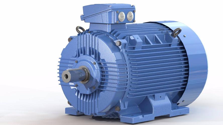
| Pole count | Synchronous speed (50 / 60 Hz) | Typical full-load speed | Where it fits | What changes if you switch to it |
|---|---|---|---|---|
| 2-pole | 3,000 / 3,600 rpm | ~2,900 / ~3,500 rpm | High flow, low head, clean liquids | Smaller impeller and lighter pump, but higher NPSH required and more wear |
| 4-pole | 1,500 / 1,800 rpm | ~1,450 / ~1,750 rpm | General duty, the default choice | Quieter and longer-lived; a larger impeller for the same head |
| 6-pole | 1,000 / 1,200 rpm | ~960 / ~1,150 rpm | High head, low flow, viscous liquids | Better suction behaviour and lower wear; a larger, more expensive motor |
| 8-pole and above | 750 / 900 rpm and lower | ~720 / ~870 rpm | Very high head, screw and progressive cavity pumps | Heavy and expensive; often cheaper to use a 4-pole with a gearbox |
Why the pole count moves the duty, not just the speed
Run a pump selected at 1,450 rpm with a motor that arrives at 2,900 rpm and it delivers roughly twice the flow at four times the head and eight times the power, which is the affinity law doing what it always does to an unmodified impeller [1]. Where a gearbox or belt sits between motor and pump, motor speed becomes a free variable and the ratio joins the selection; the trade-offs are in selecting a reduction gearbox.
What the Pump Asks: Load Shape and Starting Torque
Two pumps with the same running kilowatts can make very different demands on a motor, because the demand is a curve rather than a number. The shape of that curve decides the motor’s starting capability, its thermal margin and whether a VFD is a benefit or a liability.
| Pump type | Torque versus speed | Power versus speed | Starting condition | What the motor must be able to do |
|---|---|---|---|---|
| Centrifugal / mixed flow | Rises with the square of speed | Rises with the cube of speed | Light; shutoff power is low | Start direct on line; carry a modest overload at runout |
| Axial flow | Rises with the square of speed | Rises with the cube of speed | Light, but high flow at shutoff | Watch the power drawn at runout, not at shutoff |
| Gear / lobe (PD) | Nearly constant across speed | Rises linearly with speed | Heavy if started against pressure | Breakaway torque above running torque; relief valve protection |
| Plunger / piston (PD) | Constant, pulsating | Nearly constant with speed | Heavy, with torque peaks per stroke | Flywheel or pulsation damping; breakaway margin; check peak torque |
| Progressive cavity | Nearly constant, high at breakaway | Linear with speed | Very heavy when the stator is dry or the fluid is cold | High starting torque or a VFD with torque boost; never size on running kW alone |
The light-start family: centrifugal and axial
The centrifugal row explains why so many pump motors start happily on a direct-on-line starter: at zero speed the torque required is near zero, so the motor’s 2.0 to 2.5 times rated starting torque has nothing to fight. The same motor on a progressive cavity pump starting against a cold, viscous product can stall, because the torque required at zero speed is close to the running torque and a standard design N motor only just covers it.
The loaded-start family: gear, plunger and progressive cavity
Positive displacement duties therefore need a separate calculation. Take the running torque at the duty point, multiply by 1.3 to 1.5 to cover breakaway and cold-start viscosity, and compare that with the starting torque the motor actually delivers at the supply voltage available. If the margin is thin, the answer is a larger frame, a different starter, or a VFD with torque boost, not a bigger nameplate alone. The load classes behind this are set out in our pump motor application map, and the same constant-torque reasoning appears in air compressor motors.
From Duty Point to Motor Rating
With the speed fixed and the load shape known, the rating follows arithmetic rather than judgement. The example below is a clean-water centrifugal duty; every number can be recomputed.
| Step | Quantity | Expression | Result |
|---|---|---|---|
| 1 | Hydraulic power | P = ρ·g·Q·H / 3.6×10⁶ with Q in m³/h, H in m | 1.47 kW |
| 2 | Shaft power | 1.47 / 0.62 (pump efficiency) | 2.37 kW |
| 3 | Shaft torque at 2,900 rpm | T = 9550·P/n | 7.8 N·m |
| 4 | Motor selection | Next standard rating above 2.37 kW | 3 kW, IE3 at 87.7% |
| 5 | Electrical input | 2.37 / 0.877 | 2.70 kW |
| 6 | Annual energy at 4,000 h | 2.70 × 4,000 | 10,800 kWh |
The step that decides the cost
Step 4 is where most of the money is decided. A 3 kW motor carries 2.37 kW at 79 per cent load, which is a healthy working point. Buying 4 kW “for margin” drops the load to 59 per cent, where efficiency and power factor both fall away from the design point, and the user pays for that in every operating hour for the life of the plant. The efficiency classes themselves are defined in IEC 60034-30-1 [2], and the difference between IE2 and IE3 at this size is worth roughly three points; see motor efficiency classes.
Two corrections are then applied to the rated output, not to the duty. If the motor sits above 1,000 m or in an ambient above 40 °C, the nameplate figure has to be derated, which the heat section covers. And on a 60 Hz supply instead of 50 Hz, the same motor runs 20 per cent faster at the same V/Hz ratio, which changes the pump duty as well as the motor. Torque arithmetic in isolation is covered in motor torque calculation.
The Mechanical Marriage: Flange, Shaft, Coupling and Belt
Interface decisions are settled on a drawing, not in a calculation, and this is where the expensive mistakes live. A motor can be electrically perfect and still be the wrong motor because its flange has the wrong bolt circle.
| Interface | What must match | What goes wrong when it does not |
|---|---|---|
| Flange and foot pattern | IEC B3, B5, B14 or B35; NEMA 56C, 143TC, 145TC; bolt circle, spigot diameter, bolt size | An adapter plate is machined on site, alignment is lost, and the coupling wears |
| Shaft | Diameter, length, key or flat, shoulder position, thread on the end | A re-bored coupling, a shortened key, or a shaft that bottoms in the pump bore |
| Radial load at the shaft end | Permitted radial load at a stated distance from the shoulder | Belt tension overloads the front bearing; failure appears in months, not days |
| Axial load | Whether the pump thrust passes through the motor bearing | On vertical inline sets, a rigid coupling can push pump thrust into the motor |
| Mounting orientation | Horizontal foot, vertical flange, shaft up or down | Wrong oil level in the bearing, or condensation that cannot drain |
| Coupling type | Flexible, rigid, spacer, or close-coupled register | Rigid couplings transmit misalignment as bearing load instead of absorbing it |
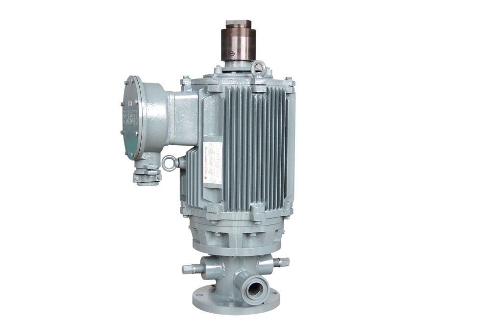
Radial load: the number that is not on the nameplate
Radial load is the one number a catalogue makes easy to miss. Every motor datasheet states a permissible radial load at a stated distance from the shaft shoulder, and that figure falls as the distance grows. A belt pulley mounted further out than the reference distance, or tightened until the belt does not slip, can double the load the front bearing sees. The bearing then fails at 3,000 hours and the motor is blamed.
Vertical inline sets and the thrust question
Vertical inline pumps add a second trap. The pump’s weight and hydraulic thrust are meant to be carried by the pump’s own bearings or by a thrust arrangement in the coupling; if the motor is bolted directly to the pump lantern with a rigid coupling, whatever the pump cannot absorb goes into the motor’s front bearing. Ask explicitly who carries the thrust, and put the answer in the RFQ. Nameplate data that supports this conversation is decoded in reading a motor nameplate.
Heat in a Pump Room: Derating and Enclosure
A pump motor is usually the hottest thing in a small, wet, poorly ventilated room, and its rating assumes none of that. The nameplate figure is quoted at 40 °C ambient and 1,000 m altitude, with free air around a self-cooled frame. Move away from those conditions and the figure has to come down.
The usual rules are about 1 per cent of output per kelvin above 40 °C, and 0.5 to 1 per cent per 100 m above 1,000 m. They compound: a motor in a 46 °C plant room at 2,000 m has roughly 15 per cent less capability than its nameplate, which turns a 3 kW motor into a 2.55 kW motor against a 2.37 kW duty, barely enough and with no margin for a hot afternoon. Temperature rise limits and insulation classes are defined in IEC 60034-1 [3], and enclosure protection in IEC 60034-5 [4].
Enclosure choice decides where the heat goes
A standard totally enclosed fan-cooled motor is IP55 and is the normal answer for indoor pump duty. A washdown area wants IP65 and a painted or stainless frame. An acoustic hood, fitted to meet a noise limit [5], is the classic failure: it removes the airflow the rating depended on, and the motor that was fine on the test bed runs 20 K hotter in service. Where noise is the constraint, the honest options are a larger, slower motor or forced ventilation inside the hood, not a bigger kilowatt figure.
Starting Method Follows the Pump
Once the load shape is known, the starter is not a preference. A centrifugal pump and a loaded positive displacement pump need different starting arrangements, because the same starter that protects the supply can destroy the pump’s ability to start.
| Method | Starting current | Starting torque | Fits | Fails when |
|---|---|---|---|---|
| Direct on line | 6–8 × rated | 2.0–2.5 × rated | Centrifugal pumps on a supply that can take the dip | The supply cannot absorb the dip, or the pump starts loaded |
| Star-delta | 2.2–2.5 × rated | 0.7–0.8 × rated (about one third) | Large centrifugal pumps starting unloaded | A positive displacement pump, which needs the torque that was just cut to a third |
| Soft starter | Limited, typically 3 × rated | About 0.47 × rated at 3 × current, since torque falls with current squared | Centrifugal duties where the dip must be limited | Loaded positive displacement duties: the torque is simply not there |
| VFD | 1.5 × rated, sustained | 1.5 × rated from zero speed | Anything that must start loaded, or needs flow control | The motor is not suitable for converter duty, or minimum speed is set too low |
Soft starting is the row that catches people out. Limiting current to three times rated sounds considerate, but motor torque varies with the square of current, so three times current yields about 0.47 times rated torque: not three times, and not even once. On a centrifugal pump that is ample. On a gear pump starting against a full discharge line it is the reason the motor hums and the overload trips.
When the Drive Is a VFD
Variable speed is the right answer for a large share of pump duties, and the affinity laws explain why: at 80 per cent speed a centrifugal pump delivers about 80 per cent flow at 64 per cent head for roughly half the power. What the affinity laws do not tell you is what the converter does to the motor.
The winding sees fast switching edges and reflected wave overvoltage, which stresses insulation beyond what a sinusoidal supply does. Harmonic currents add rotor and stator heating, so a motor run on a converter is derated relative to its mains rating. Common-mode voltage drives shaft voltage, which discharges through the bearings and leaves the characteristic fluting pattern on the raceways. The interface between motor and converter, including installation guidance and derating, is the subject of IEC TS 60034-25 [6], and the EMC requirements for the complete drive are in IEC 61800-3 [7].
What to check before a VFD goes on a pump
Confirm the motor is converter-capable or converter-duty, and by which definition. Keep the minimum speed above about 25 to 30 per cent of rated speed unless the motor has forced ventilation, because a self-cooled fan moves almost no air at low speed. Insulate one bearing or fit a shaft grounding ring above roughly 30 kW. And check that the pump’s own minimum flow is respected, because a VFD makes it easy to run a pump at a flow the hydraulics were never designed for.
Where the duty is small, low-flow and battery-fed, a brushless DC pump motor changes the arithmetic entirely [8]; that route is covered in BLDC motors for pumps and micro pump motors, and the controller differences in VFD motors versus normal motors.
Acceptance: What to Test and What to Ignore
A pump-motor package is accepted against two different sets of numbers, and confusing them causes arguments. The pump is accepted on hydraulic performance, the motor on electrical and thermal performance, and the standard behind the first one defines how much tolerance is allowed.
Hydraulic acceptance: specify the grade
ISO 9906 sets three grades for hydraulic acceptance testing of rotodynamic pumps: grades 1B, 1E and 1U with the tightest tolerances, grades 2B and 2U with broader ones, and grade 3B broader still [9]. That matters when comparing quotations, because two pumps both described as “tested to ISO 9906” can legitimately differ by several points at the duty point if one is grade 1B and the other grade 3B. Specify the grade, not the standard number.
Motor acceptance: ask for measured values
On the motor side, ask for the measured quantities and not the type test reference: no-load current, winding resistance per phase, insulation resistance, and a temperature rise at a stated current and ambient. A motor whose datasheet gives an insulation class but no rise figure has told you half of what you need. The quality-system side of supplier qualification is covered by ISO 9001 [10], which is a baseline rather than a differentiator.
What to Put in the RFQ
Most wrong pump motors are ordered by an enquiry that named a kilowatt figure and nothing else. These ten items turn the enquiry into something a supplier can answer correctly the first time.
| Item | Why the supplier needs it |
|---|---|
| Duty point: flow and head, with the liquid | Fixes hydraulic power and the pump’s operating point |
| Pump type | Sets the load shape and therefore the starting torque requirement |
| Required speed, or the transmission ratio | Chooses the pole count; changing it moves the whole duty curve |
| Starting condition | Loaded or unloaded, valve open or closed, cold or warm; this decides the starter and the frame |
| Supply voltage, frequency and phase | Determines winding, and whether the duty survives a 50/60 Hz change |
| Flange and shaft drawing | The interface that cannot be adjusted later without machining |
| Radial and axial loads, with the point of application | Belt drives and vertical inline sets both transfer load the bearing must be rated for |
| Ambient, altitude, humidity and IP requirement | Sets the derating factor and the enclosure |
| Annual running hours and duty cycle | Decides whether efficiency differences pay back, and sizes the thermal margin |
| Certification and documentation route | Changes insulation, marking, test plan and the paperwork you will be audited against |
Which row to add if there is only room for one
If only one row can be added to an existing template, add the fourth. Starting condition is the item that most often separates a motor that works from a motor that trips, and it costs one question to ask.
Five Mistakes That Reach the Factory
- Sizing on the pump’s nameplate power. That figure is the pump’s shaft requirement at its design point, not the motor’s electrical input. Adding a margin on top of it double-counts.
- Changing pole count to fix a flow problem. Halving the speed does not halve the flow; with static head in the system it can return less than half, and the head falls by the square.
- Using a star-delta starter on a loaded positive displacement pump. The torque reduction to about one third is the point of the starter, and it is also why the pump will not break away.
- Ignoring the radial load on a belt-driven set. Belt tension is set by feel in most workshops, and the bearing is the part that records the decision.
- Fitting an acoustic hood around a standard motor. The hood removes the airflow the rating assumed; either ventilate it or fit a slower, larger motor.
Why Greensky Power
We build pump motors in the same frames this article talks about, 63 to 132, three-phase induction and brushless, and we quote them from the duty point and not from a kilowatt figure. Our standard enquiry form asks for the ten items above, so the first quotation usually survives the first design review.
What we can supply is the motor plus the interface: IEC B5 and B14 flanges machined to your pump lantern, shafts to your drawing, terminal boxes positioned for the room rather than for the catalogue, IP55 or IP65 as the installation needs, and converter-capable windings where a VFD is part of the package. The pump-specific range is on the pump motor page, and the custom programme is described under custom electric motor manufacturing.
If you are still choosing between technologies and not between suppliers, the general-purpose baseline is explained in what a general purpose motor is, and it is better read before a specification hardens around the wrong frame standard.
References
- Gülich, J. F. (2014). Centrifugal pumps (3rd ed.). Springer. https://doi.org/10.1007/978-3-642-40114-5
- International Electrotechnical Commission. (2025). IEC 60034-30-1:2025 — Rotating electrical machines, Part 30-1: Efficiency classes of line operated AC motors (IE code). IEC. https://webstore.iec.ch/en/publication/91195
- International Electrotechnical Commission. (2026). IEC 60034-1:2026 — Rotating electrical machines, Part 1: Rating and performance. IEC. https://webstore.iec.ch/en/publication/89961
- International Electrotechnical Commission. (2020). IEC 60034-5:2020 — Rotating electrical machines, Part 5: Degrees of protection provided by the integral design of rotating electrical machines (IP code). IEC. https://webstore.iec.ch/en/publication/64224
- International Electrotechnical Commission. (2021). IEC 60034-9:2021 — Rotating electrical machines, Part 9: Noise limits. IEC. https://webstore.iec.ch/en/publication/66184
- International Electrotechnical Commission. (2022). IEC TS 60034-25:2022 — Rotating electrical machines, Part 25: AC electrical machines used in power drive systems, Application guide. IEC. https://webstore.iec.ch/en/publication/66456
- International Electrotechnical Commission. (2022). IEC 61800-3:2022 — Adjustable speed electrical power drive systems, Part 3: EMC requirements and specific test methods for PDS and machine tools. IEC. https://webstore.iec.ch/en/publication/65056
- Krishnan, R. (2010). Permanent magnet synchronous and brushless DC motor drives. CRC Press. https://doi.org/10.1201/9781420014235
- International Organization for Standardization. (2012). ISO 9906:2012 — Rotodynamic pumps, Hydraulic performance acceptance tests, Grades 1, 2 and 3. ISO. https://www.iso.org/standard/41202.html
- International Organization for Standardization. (2026). ISO 9001:2026 — Quality management systems, Requirements. ISO. https://www.iso.org/standard/9001
FAQ
Q: What size motor does my pump need?
Start from hydraulic power: density times gravity times flow times head, with flow in cubic metres per second and head in metres. Divide by pump efficiency for shaft power, then by motor efficiency for electrical input. A 12 m³/h, 45 m duty at 62 per cent pump efficiency needs 1.47 kW hydraulically, 2.37 kW at the shaft and about 2.70 kW at the terminals through a 3 kW IE3 motor. Size on that number, not on the pump’s nameplate power.
Q: Should I use a 2-pole or 4-pole motor for a pump?
Choose on head and flow, not on habit. A 2-pole motor runs near 2,900 rpm at 50 Hz and suits high-flow, low-head duties where a small impeller at speed is cheaper than a large one. A 4-pole at about 1,450 rpm is the general-duty default and is quieter and longer-lived. A 6-pole near 960 rpm suits high-head, low-flow and viscous duties. Changing pole count moves the pump’s operating point unless the impeller is trimmed to match.
Q: Why does my pump motor trip on start-up?
Three causes cover most cases. A positive displacement pump starting against a closed valve or a full head needs breakaway torque at or above its running torque, which a motor sized on running kW cannot deliver. A star-delta starter cuts starting torque to about a third, fine for a centrifugal pump and fatal for a loaded positive displacement pump. And a centrifugal pump started against a held-shut non-return valve starts at shutoff head the motor was not sized for.
Q: Can I run a standard motor on a VFD?
Often yes, but not always safely. A standard motor on a converter faces higher winding stress from fast switching edges, extra harmonic heating, and shaft voltages that discharge through the bearings. IEC TS 60034-25 sets out the motor-converter interface including installation guidance and derating. Below about 25 to 30 per cent of rated speed a self-cooled motor loses most of its cooling, so oversize it, fit forced ventilation, or keep the minimum speed above that band.
Q: Does a bigger motor make a pump more reliable?
Not automatically. A 25 per cent margin on a 2.37 kW duty gives 3 kW at 79 per cent load, which is healthy. Jumping to 4 kW drops the load to 59 per cent, where efficiency and power factor fall away from the design point. Reliability comes from correct speed, correct starting torque, and a flange and shaft load the bearing can carry, not from extra kilowatts.
Q: What must I send a supplier to get the right pump motor?
Six things decide it: the duty point in flow and head, the pump type so the load shape is known, the speed or transmission ratio, the starting condition including whether the pump starts loaded, the mounting interface with flange standard and shaft dimensions, and the environment with ambient, altitude and ingress requirement. Add annual volume and certification route. A supplier quoting from a kilowatt figure alone is guessing at five of the six.
Greensky Power builds pump motors in 63 to 132 frames, three-phase induction and brushless, with IEC B5 and B14 flanges machined to your lantern, shafts to your drawing, IP55 or IP65 enclosures and converter-capable windings. Send the duty point, the pump type and the interface drawing, and the quotation comes back with the speed, frame and starting condition already checked. Contact the engineering team.