
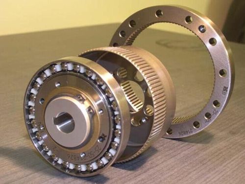
Harmonic Drive vs Planetary Gear: Complete Engineering Comparison
[ez-toc]
Quick Answer
A harmonic drive (strain wave gear) uses the controlled elastic deformation of a flexspline to achieve single-stage reduction ratios of 50:1–320:1 with near-zero backlash (≤1 arc-min), while a planetary gear uses rigid sun-planet-ring gear meshing to deliver multi-stage ratios of 3:1–100:1 with higher torque density and efficiency up to 98% per stage. Harmonic drives excel in precision robotics and aerospace applications where positioning accuracy is critical, whereas planetary gears dominate industrial automation, conveyors, and heavy-duty machinery where torque capacity, durability, and cost-efficiency matter most.
According to IEC 60034-30-1 and NEMA MG 1 standards, the motor efficiency class paired with either gearbox type directly affects system-level energy consumption — the International Energy Agency (IEA) reports that motor-driven systems account for 53% of global electricity use, making gearbox selection a system-level energy decision.
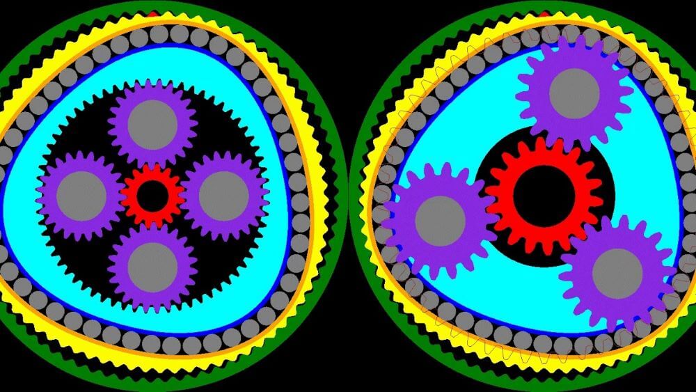
What Is a Harmonic Drive?
A harmonic drive — patented by American engineer C.W. Musser in 1959 (U.S. Patent 2,906,143) — is a precision gear mechanism that transmits motion through the controlled elastic deformation of a thin-walled flexible component. Unlike conventional rigid-gear transmissions, harmonic drives rely on metal flexibility to achieve extremely high reduction ratios in a single stage.
The three core components are:
- Wave Generator (WG): An elliptical cam with a thin-wall ball bearing that inserts into the flexspline, forcing it into an elliptical shape.
- Flexspline (FS): A cup-shaped, thin-walled flexible gear with external teeth. It deforms elliptically under the wave generator and serves as the output element.
- Circular Spline (CS): A rigid internal gear ring with teeth that mesh with the flexspline at two zones 180° apart. It is fixed to the housing.
The flexspline typically has 2 fewer teeth than the circular spline. As the wave generator rotates, the meshing zone travels around the circumference, causing the flexspline to rotate slowly in the opposite direction — producing reduction ratios from 50:1 to 320:1 in a single stage.
What Is a Planetary Gear?
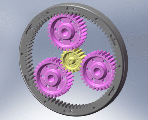
A planetary gear (epicyclic gear) is a compact power transmission system comprising a central sun gear, multiple orbiting planet gears, an outer ring gear (internal teeth), and a planet carrier that serves as the output. The name derives from the analogy to planets orbiting the sun.
Key characteristics per IEC 60034-1 classification:
- Single-stage ratios: 3:1–10:1; multi-stage (2–4 stages) ratios up to 10,000:1
- Load is shared across multiple planet gears (typically 3–5), distributing stress and increasing torque density
- Coaxial input-output alignment enables compact, in-line mounting
- Rigid tooth meshing provides high stiffness and excellent shock-load resistance
Planetary gears are classified under NEMA MG 1 Part 23 for gear-mounted motors and must comply with DOE 10 CFR Part 431 efficiency requirements when sold as gear motors in the U.S. market.
How Harmonic Drives Work — Step-by-Step
- Input rotation: The motor drives the wave generator at high speed. The elliptical cam is pressed against the inner wall of the flexspline.
- Flexspline deformation: As the wave generator rotates, it forces the circular flexspline into an elliptical shape. The teeth at the major axis of the ellipse engage with the circular spline, while teeth at the minor axis disengage completely.
- Meshing zone migration: With each 180° rotation of the wave generator, the meshing zone travels around the full circumference. Because the flexspline has 2 fewer teeth than the circular spline, each full wave-generator revolution advances the flexspline by exactly 2 teeth in the opposite direction.
- Simultaneous multi-tooth contact: Approximately 30% of teeth are engaged at any given moment, distributing load across many contact points — this is why harmonic drives achieve high torque density despite the flexspline’s thin wall.
- Output generation: The flexspline — attached to the output flange — rotates slowly in the direction opposite to the wave generator, delivering reduced speed and amplified torque with virtually zero backlash.
The number of deformation cycles per wave generator revolution is called the wave number. Double-wave (two meshing zones) is the most common configuration, offering simpler structure and lower flexspline stress.
How Planetary Gears Work — Step-by-Step
- Input to sun gear: The motor shaft drives the central sun gear at full speed.
- Planet gear rotation: The sun gear meshes with 3–5 planet gears, causing them to spin on their own axes (rotation) in the direction opposite to the sun gear.
- Planet gear revolution: Because the planet gears also mesh with the fixed ring gear, they are forced to orbit around the sun gear (revolution) in the same direction as the sun gear.
- Carrier output: The planet carrier — which holds the planet gear pins — rotates at a reduced speed, delivering the output torque. The gear ratio depends on the sun gear teeth (Zs), planet gear teeth (Zp), and ring gear teeth (Zr): i = 1 + Zr/Zs.
- Multi-stage stacking: For higher ratios, the output carrier of stage 1 drives the sun gear of stage 2, and so on. Each stage typically achieves 3:1–10:1, with efficiency loss of 2–5% per stage.
Harmonic Drive vs Planetary Gear: Feature Comparison Table
| Parameter | Harmonic Drive (Strain Wave Gear) | Planetary Gear |
|---|---|---|
| Transmission principle | Elastic deformation of flexspline | Rigid sun-planet-ring gear meshing |
| Core components | 3 (wave generator, flexspline, circular spline) | 4+ (sun gear, planet gears, ring gear, carrier) |
| Single-stage ratio | 50:1 – 320:1 | 3:1 – 10:1 |
| Multi-stage ratio | Up to 1,000:1 (rarely used) | Up to 10,000:1 (4-stage) |
| Backlash | ≤1 arc-min (near zero) | 1–6 arc-min (precision types: ≤1 arc-min) |
| Efficiency (single-stage) | 70% – 90% | 95% – 98% |
| Torque density | High (compact for ratio) | Very high (load sharing across planets) |
| Shock load resistance | Moderate (flexspline fatigue risk) | Excellent (rigid meshing) |
| Lifespan (L10) | 7,000 – 10,000 hours (rated load) | 20,000 – 50,000+ hours (rated load) |
| Weight (equivalent ratio) | Lighter | Heavier |
| Cost | 30% – 100% higher | Baseline (economical) |
| Typical max torque | Up to ~500 N·m (larger sizes) | Up to ~20,000 N·m (industrial sizes) |
| Standard reference | Manufacturer-specific (Harmonic Drive LLC, KOFON) | IEC 60034-1, NEMA MG 1 Part 23 |
Engineering Data: Efficiency, Temperature Limits & Torque Formulas
1. Gearbox Efficiency Comparison
Efficiency data from manufacturer datasheets and IEC 60034-30-1 motor efficiency framework:
| Gearbox Type | Stages | Reduction Ratio | Max. Efficiency | Backlash | Source |
|---|---|---|---|---|---|
| maxon GPX 22 (planetary) | 1 | 3.9:1 | 90% | 1.4° | maxon datasheet |
| maxon GPX 26 (planetary) | 1 | 3.9:1 | 90% | 0.75° | maxon datasheet |
| maxon GPX 37 LN (planetary) | 2 | 16:1 | 80% | 0.6° | maxon datasheet |
| maxon GPX 32 HP (planetary) | 3 | 103:1 | 65% | 0.9° | maxon datasheet |
| Siemens SIMOGEAR (coaxial helical) | 2 | 3.5–60:1 | ≥96% | — | Siemens catalog |
| Harmonic Drive SHD/CSF | 1 | 50–160:1 | 70–85% | ≤1 arc-min | Harmonic Drive LLC catalog |
| Harmonic Drive CSG/SHG | 1 | 50–160:1 | 75–90% | ≤1 arc-min | Harmonic Drive LLC catalog |
Key insight: Planetary gears maintain 90%+ efficiency in single-stage configurations and degrade 5–10% per additional stage. Harmonic drives achieve 70–90% efficiency — lower than planetary gears at comparable ratios — because energy is consumed by the continuous flexing of the flexspline. This flexing also generates heat, which is a limiting factor in continuous-duty applications.
2. IEC 60034-1 Insulation Class Temperature Limits
Motor insulation class — defined by IEC 60034-1 — determines the maximum allowable operating temperature. Gearbox selection impacts motor loading and therefore thermal performance:
| Insulation Class | Max Temperature | Temperature Rise Limit | Typical Application |
|---|---|---|---|
| Class A | 105°C | 60 K | Low-duty, obsolete |
| Class E | 120°C | 75 K | Light industrial |
| Class B | 130°C | 80 K | Standard industrial motors |
| Class F | 155°C | 100 K | Most industrial gear motors (maxon EC-max 30, Siemens SIMOTICS) |
| Class H | 180°C | 125 K | High-temperature, heavy-duty (Faulhaber 2668CR series) |
3. IEC 60034-30-1 Motor Efficiency Classes (IE1–IE5)
The motor paired with the gearbox must comply with regional efficiency mandates. The DOE will require IE4 (Super-Premium) efficiency for 1–750 hp motors starting June 1, 2027, projected to save U.S. businesses $8.8 billion and avoid 92 million metric tons of CO₂ over 30 years.
| IEC Class | NEMA Equivalent | Loss Reduction vs IE1 | Regulatory Status |
|---|---|---|---|
| IE1 | Standard Efficiency | Baseline | Phased out in most markets |
| IE2 | High Efficiency | 10% less loss | Minimum in some regions |
| IE3 | Premium Efficiency | 20% less loss | U.S. minimum since 2007; EU minimum since 2021 |
| IE4 | Super-Premium | 30% less loss | DOE mandatory June 2027 (1–750 hp) |
| IE5 | Ultra-Premium | 40% less loss | Under development; not yet NEMA-defined |
4. Core Torque and Efficiency Formulas
Planetary gear ratio (single-stage):
i = 1 + Zr / Zs
Where Zr = ring gear teeth, Zs = sun gear teeth. For multi-stage: i_total = i₁ × i₂ × … × iₙ
Harmonic drive ratio:
i = Zfs / (Zcs − Zfs)
Where Zfs = flexspline teeth, Zcs = circular spline teeth. Since Zcs − Zfs = 2 (typically), the ratio simplifies to i = Zfs / 2. For a 100-tooth flexspline: i = 50:1.
Output torque (both types):
T_out = T_in × i × η
Where T_in = motor torque, i = gear ratio, η = gearbox efficiency.
System efficiency (motor + gearbox):
η_system = η_motor × η_gearbox
Example: IE4 motor (η = 94%) + 2-stage planetary gearbox (η = 90%): η_system = 0.94 × 0.90 = 84.6%. The IEA estimates that optimizing motor-driven system efficiency — including gearbox selection — could reduce global industrial electricity consumption by 20–30%.
Harmonic Drive flexspline fatigue life (L10):
Lh = Ln × (Tr / Tav)³ × (Nr / Nav)
Where Ln = rated life (7,000 or 10,000 h per Harmonic Drive LLC catalog), Tr = rated torque, Tav = average load torque, Nr = rated input speed, Nav = average input speed. This cubic relationship means that doubling the load torque reduces life by a factor of 8.
SKF bearing life (L10h) for planetary gear planet bearings:
L10h = (1,000,000 / 60n) × (C/P)³
Where C = basic dynamic load rating, P = equivalent dynamic load, n = rotational speed (rpm). This formula, from SKF bearing life calculation standards, is critical for verifying planet bearing life in multi-stage planetary gearboxes.
NEMA MG 1 service factor:
SF = T_peak / T_rated
NEMA MG 1 specifies service factors (typically 1.0–1.15 for standard motors, up to 1.25 for special designs) that account for occasional overload conditions. The gearbox must be sized to handle motor peak torque multiplied by the service factor.
5. Harmonic Drive Torque Limits
Per Harmonic Drive LLC engineering data, the flexspline — the component subjected to repeated elastic deformation — determines torque capacity. Key torque thresholds:
- Rated torque: Continuous load at rated speed, based on infinite flexspline fatigue life.
- Repeated peak torque: Allowable cyclic overload; must remain within flexspline fatigue limit.
- Momentary peak (impact) torque: Must not exceed the allowable limit; maximum bending cycles: 1.0 × 10⁴. Formula: N = 1.0 × 10⁴ / (2 × n/60 × t), where N = allowable occurrences, n = wave generator speed (rpm), t = impact duration (sec).
- Ratcheting torque: 8–9× rated torque — teeth disengage, causing loss of concentricity and accelerated wear.
- Buckling torque: 16–17× rated torque — flexspline suffers plastic deformation; catastrophic failure.
Best Applications for Harmonic Drives
| Application | Why Harmonic Drive? | Typical Ratio |
|---|---|---|
| Industrial robot joints (6-axis arms) | Zero backlash for repeatability; compact size fits joint envelopes; high single-stage ratio eliminates multi-stage backlash accumulation | 50:1 – 160:1 |
| Collaborative robots (cobots) | Lightweight for arm payload optimization; smooth motion for human-safe operation; high torsional stiffness for responsive torque sensing | 100:1 – 160:1 |
| Semiconductor manufacturing equipment | Sub-arc-min positioning accuracy for wafer alignment; low vibration for cleanroom environments | 80:1 – 120:1 |
| Aerospace actuation systems | High reduction in minimal weight/space; qualified per DO-160G and AS9100D standards | 100:1 – 320:1 |
| Medical/surgical robotics | Precision positioning; zero backlash for haptic feedback; compact form factor for end-effectors | 50:1 – 100:1 |
Best Applications for Planetary Gears
| Application | Why Planetary Gear? | Typical Ratio |
|---|---|---|
| Industrial automation (conveyors, indexing tables) | High torque capacity; excellent shock resistance; cost-effective for continuous duty; IE3/IE4 motor compatibility | 3:1 – 100:1 |
| Servo-driven CNC machinery | Low backlash precision types (≤1 arc-min); high torsional stiffness for dynamic positioning; high input speed capability | 5:1 – 40:1 |
| AGV and mobile robotics drivetrains | Compact inline design; high efficiency extends battery life; handles acceleration/deceleration shock loads | 10:1 – 50:1 |
| Packaging and filling machinery | High cycle durability; multi-stage ratios for synchronized multi-axis motion; easy maintenance | 10:1 – 100:1 |
| Heavy-duty material handling (cranes, hoists) | Very high torque (up to 20,000 N·m); robust rigid construction; long service life (20,000+ hours) | 20:1 – 300:1 |
Selection Guide: Step-by-Step Process
Step 1: Define Application Requirements
Document the required output speed, continuous torque, peak torque, duty cycle (per IEC 60034-1 S1–S10), positioning accuracy, backlash tolerance, ambient temperature, and available envelope dimensions. Determine whether the application is precision-focused (favoring harmonic drive) or power-focused (favoring planetary gear).
Step 2: Calculate Required Gear Ratio
Using the formula i = n_motor / n_output, determine the required reduction. If i ≤ 10:1, a single-stage planetary gear is optimal. If 10:1 < i ≤ 100:1, evaluate 2–3 stage planetary gears against single-stage harmonic drives. If i > 100:1, harmonic drives or 3–4 stage planetary gears are the candidates.
Step 3: Evaluate Backlash Requirements
For robotics, semiconductor, and precision positioning applications requiring ≤1 arc-min backlash, harmonic drives are typically the default choice. For general automation with 3–6 arc-min tolerance, precision planetary gears offer better cost-efficiency. For non-positioning applications (conveyors, pumps), standard planetary gears with 6+ arc-min backlash are sufficient.
Step 4: Torque and Life Verification
For harmonic drives, apply the fatigue life formula Lh = Ln × (Tr/Tav)³ × (Nr/Nav) to verify that L10 life meets application requirements. Remember the cubic relationship — a 50% torque overload reduces life by 87.5%. For planetary gears, verify planet bearing life using the SKF L10h formula L10h = (1,000,000/60n) × (C/P)³ and confirm that the rated torque exceeds the application’s peak torque multiplied by the NEMA MG 1 service factor.
Step 5: Efficiency and Thermal Analysis
Calculate system efficiency: η_system = η_motor × η_gearbox. Compare the energy cost over the system lifetime — the IEA reports that energy accounts for 95–97% of a motor system’s total lifecycle cost. For continuous-duty applications, verify that gearbox heat dissipation keeps motor winding temperature within the IEC 60034-1 insulation class limit (e.g., 155°C for Class F). Harmonic drives may require derating for continuous operation due to flexspline heat generation.
06: Step 6: Cost and Total Cost of Ownership (TCO) Analysis
Compare purchase price, expected maintenance intervals, lubrication requirements, and replacement cost. Harmonic drives typically cost 30–100% more than equivalent planetary gears but may be justified by precision requirements. Use the TCO formula: TCO = Purchase + Energy + Maintenance + Downtime. The DOE estimates that upgrading to IE4 motor efficiency alone saves $8.8 billion over 30 years — gearbox efficiency has a comparable compounding effect.
Step 7: Standards Compliance Verification
Confirm that the motor-gearbox assembly complies with applicable standards: IEC 60034-1 (rating and performance), IEC 60034-30-1 (efficiency class), NEMA MG 1 (U.S. motor and gear-mounted motor specification), DOE 10 CFR Part 431 (U.S. efficiency mandate), and IEC 60034-5 (IP protection class). For aerospace applications, verify DO-160G and AS9100D compliance.
Step 8: Prototype Testing and Validation
Order samples and conduct accelerated life testing under representative load cycles. Measure backlash, efficiency, temperature rise, and noise. For harmonic drives, monitor flexspline stress at the tooth root — the predominant fatigue crack initiation site per IEEE research (DOI: 10.19287/j.mtmt.1005-2402.2023.08.011). For planetary gears, verify bearing temperature and gear tooth contact pattern.
Common Engineering Mistakes
Mistake 1: Overloading Harmonic Drives Beyond Rated Torque
Problem: Selecting a harmonic drive based on average torque without accounting for peak loads. Due to the cubic life relationship, a 1.5× overload reduces L10 life by 70%.
Correction: Always size harmonic drives for peak torque, not average. Apply the fatigue life formula with actual load spectrum data. If peak torque exceeds 2× rated, consider a larger size or switch to a planetary gear.
Mistake 2: Using Harmonic Drives in High-Impact Applications
Problem: Installing harmonic drives in palletizers, stamping presses, or other equipment with frequent emergency stops. The flexspline absorbs impact energy through elastic deformation, accelerating fatigue crack initiation at the tooth root.
Correction: For applications with frequent shock loads, select planetary gears with their rigid load-sharing architecture. The NEMA MG 1 service factor (1.0–1.25) provides additional margin for shock loading.
Mistake 3: Ignoring Efficiency Loss in Multi-Stage Planetary Gears
Problem: Specifying a 4-stage planetary gearbox (i = 1,000:1) without recognizing that efficiency drops to ~66% (maxon GPX 22 4-stage: 66% efficiency). This 34% energy loss becomes heat, requiring larger motors and cooling systems.
Correction: For ratios above 100:1, compare 4-stage planetary (η ≈ 66%) against single-stage harmonic drive (η ≈ 80%). Evaluate system efficiency η_system = η_motor × η_gearbox for the complete picture per IEA guidance.
Mistake 4: Selecting Planetary Gears for Ultra-Precision Positioning
Problem: Using standard planetary gears (3–6 arc-min backlash) in semiconductor wafer alignment or surgical robotics, where sub-arc-min accuracy is required. Even “low-backlash” planetary gears (1–3 arc-min) may exhibit backlash growth after wear-in.
Correction: For ≤1 arc-min positioning, harmonic drives provide inherently zero backlash due to the continuous flexspline-circular spline pre-load. Ultra-precision planetary gears (≤1 arc-min) exist but approach harmonic drive cost while offering inferior repeatability.
Mistake 5: Neglecting Thermal Management for Harmonic Drives
Problem: Operating harmonic drives at rated torque and high speed in continuous-duty (S1) applications without verifying temperature rise. Flexspline deformation generates significant heat — a 10°C temperature rise can halve flexspline fatigue life.
Correction: Derate harmonic drive torque by 20–30% for continuous-duty applications. Monitor flexspline temperature and ensure it stays within the material’s safe operating range (typically ≤80°C for standard lubricants). Consider synthetic lubricants for high-temperature operation.
Mistake 6: Mismatching Motor Efficiency Class with Gearbox Type
Problem: Pairing an IE4 motor (94% efficiency) with a low-efficiency 4-stage planetary gearbox (66%), resulting in a system efficiency of only 62%. The IE4 investment is wasted by gearbox losses.
Correction: Always calculate system efficiency. Per DOE 10 CFR Part 431, IE4 motors become mandatory for 1–750 hp in June 2027 — pair them with high-efficiency gearboxes (≥95% per stage) to realize the intended energy savings. The IEA estimates 20–30% industrial energy savings are achievable through system-level optimization.
Troubleshooting Table: Problem → Cause → Solution
| Problem | Likely Cause | Solution |
|---|---|---|
| Harmonic drive flexspline cracking at tooth root | Repeated peak torque exceeding fatigue limit; impact loads above momentary peak rating | Reduce peak load; select larger unit; switch to planetary gear for shock-load applications; verify with fatigue life formula Lh = Ln × (Tr/Tav)³ × (Nr/Nav) |
| Harmonic drive ratcheting (teeth skipping) | Output torque exceeding 8–9× rated (ratcheting torque); housing stiffness insufficient | Reduce load; increase housing rigidity; verify ratcheting torque per manufacturer catalog; never operate after ratcheting occurs — replace unit |
| Planetary gear excessive backlash after service | Bearing wear; gear tooth wear from inadequate lubrication; carrier deformation | Replace bearings; verify lubrication interval; check gear tooth contact pattern; replace worn gear sets; use SKF L10h formula to predict bearing replacement interval |
| Planetary gear overheating | Overload; insufficient lubrication; high input speed exceeding rated limit; blocked ventilation | Verify load against rated torque; check oil level and viscosity; reduce input speed; clean cooling fins; monitor motor winding temperature per IEC 60034-1 Class F limit (155°C) |
| Harmonic drive efficiency degradation over time | Lubricant breakdown; flexspline fatigue micro-cracks; wave generator bearing wear | Replace lubricant per manufacturer schedule; inspect flexspline for crack initiation; replace wave generator bearing; log efficiency trend data |
| Planetary gear noise and vibration increase | Gear tooth pitting; planet bearing damage; misalignment between motor and gearbox | Perform vibration spectrum analysis; replace damaged gears/bearings; verify coaxial alignment; check coupling balance |
| Harmonic drive output position error drift | Circular spline tooth wear; flexspline circumferential deformation asymmetry; temperature-induced dimensional change | Re-calibrate position feedback; inspect tooth engagement pattern; verify operating temperature stability; consider thermal compensation in control loop |
| Motor trip on overload when paired with gearbox | Gearbox efficiency lower than assumed; starting torque exceeds motor breakdown torque; wrong gear ratio selected | Recalculate system efficiency η_system = η_motor × η_gearbox; verify motor torque-speed curve against required starting torque; verify NEMA MG 1 service factor adequacy; size motor for actual gearbox loss |
FAQ
Which is more efficient: harmonic drive or planetary gear?
Planetary gears are generally more efficient. Single-stage planetary gears achieve 95–98% efficiency, while single-stage harmonic drives achieve 70–90%. The efficiency gap widens at higher ratios because planetary gears require multiple stages (each losing 2–5%), while harmonic drives maintain single-stage configuration but lose energy to continuous flexspline deformation. Per IEC 60034-30-1, the motor efficiency class (IE1–IE5) compounds this difference: an IE4 motor paired with a 96%-efficient planetary gearbox achieves 90.2% system efficiency, versus 79.9% with an 85%-efficient harmonic drive.
Can a harmonic drive replace a planetary gear?
Only in specific applications. Harmonic drives are ideal when you need high single-stage ratios (50:1–320:1), zero backlash, and compact size — typical in robotics and precision positioning. They are not suitable for high-torque, high-shock-load, or continuous-duty industrial applications where planetary gears excel. The flexspline’s fatigue life (7,000–10,000 hours L10 at rated load) is significantly shorter than planetary gear life (20,000+ hours), making harmonic drives less suitable for 24/7 industrial operation.
What is the backlash difference between harmonic drive and planetary gear?
Harmonic drives have virtually zero backlash (≤1 arc-min) because the flexspline teeth are preloaded against the circular spline at all times. Standard planetary gears have 3–6 arc-min backlash; precision planetary gears achieve 1–3 arc-min; ultra-precision types reach ≤1 arc-min but approach harmonic drive cost. For applications where backlash directly affects positioning accuracy (robotics, CNC, semiconductor), harmonic drives are typically the default choice.
How long do harmonic drives last compared to planetary gears?
Per Harmonic Drive LLC engineering data, harmonic drive L10 life (the life at which 90% of units survive) is 7,000 hours for standard series (CSF, CSD, SHF, SHD) and 10,000 hours for high-torque series (CSG, SHG) at rated load and speed. L50 (average) life is 35,000–50,000 hours. Planetary gears, by contrast, typically achieve 20,000–50,000+ hours L10 life under rated conditions, with SKF bearing life calculations providing the limiting factor. The cubic torque-life relationship of harmonic drives means overloading is much more damaging than for planetary gears.
Are harmonic drives more expensive than planetary gears?
Yes, typically 30–100% more expensive for equivalent torque ratings. The higher cost reflects precision manufacturing of the flexspline (thin-wall, fatigue-resistant alloy requiring specialized heat treatment), the wave generator’s flexible bearing, and lower production volumes. However, in applications requiring high ratios (100:1+), a single-stage harmonic drive may be more cost-effective than a 3–4 stage planetary gearbox when total system cost (including mounting hardware and motor sizing) is considered.
What standards apply to harmonic drives and planetary gears?
Planetary gear motors are governed by IEC 60034-1 (rating and performance), IEC 60034-30-1 (efficiency classes IE1–IE5), NEMA MG 1 (U.S. motor specification, Part 23 for gear-mounted motors), and DOE 10 CFR Part 431 (U.S. efficiency mandate, requiring IE4 from June 2027). Harmonic drives are governed primarily by manufacturer specifications (Harmonic Drive LLC, KOFON, Leaderdrive) rather than international efficiency standards, though the motor portion must still comply with IEC/NEMA/DOE requirements. The IEA reports that motor-driven systems account for 53% of global electricity consumption, making efficiency compliance a system-level concern.
Why Choose Greensky Power?
Greensky Power Co., Ltd. is a China-based manufacturer specializing in precision gear motor solutions for global B2B markets. Our capabilities span both planetary gear motors and harmonic drive assemblies, enabling application-optimized recommendations rather than single-technology bias.
- Vertical integration: Motor winding, gear machining, assembly, and 100% load testing under one roof — ensuring consistent quality from raw material to finished product.
- Engineering-driven selection: Our technical team applies IEC 60034-30-1 efficiency analysis, NEMA MG 1 service factor calculations, and SKF bearing life verification to every gearbox recommendation. We don’t just sell parts — we engineer solutions.
- Standards compliance: All gear motors meet IEC 60034-1 performance ratings and are available with IE3/IE4 motor efficiency classes for DOE 10 CFR Part 431 compliance. Learn more about our manufacturing capabilities.
- Global exhibition presence: We participate in major international trade shows including Hannover Messe, Canton Fair, and Automate, maintaining direct technical dialogue with global customers.
- Custom engineering: Whether your application demands the zero-backlash precision of a harmonic drive or the high-torque durability of a planetary gearbox, our R&D team delivers custom gear ratios, mounting configurations, and motor integrations within 4–6 weeks.
- Complete product ecosystem: From BLDC gear motors and right-angle gear motors to AC induction motors and DC motor solutions, we provide integrated drive systems — reducing your supplier count and integration risk.
For technical consultation on harmonic drive vs planetary gear selection, contact our engineering team with your application requirements.
References
- IEC 60034-1:2022, “Rotating electrical machines — Part 1: Rating and performance,” International Electrotechnical Commission. https://webstore.iec.ch/publication/64888
- IEC 60034-30-1:2014, “Rotating electrical machines — Part 30-1: Efficiency classes of line operated AC motors,” International Electrotechnical Commission. https://webstore.iec.ch/publication/67563
- NEMA MG 1-2024, “Motors and Generators,” National Electrical Manufacturers Association. https://www.nema.org/standards/view/Motors-and-Generators
- U.S. Department of Energy, “Energy Conservation Program: Energy Conservation Standards for Electric Motors,” 10 CFR Part 431. https://www.ecfr.gov/current/title-10/chapter-II/subchapter-D/part-431
- International Energy Agency (IEA), “Energy Efficiency 2024 — Motor Systems Analysis.” https://www.iea.org/reports/energy-efficiency-2024
- SKF Group, “Bearing Life Calculation — L10 Methodology for Gear Applications,” SKF Technical Handbook. https://www.skf.com/group/technical-insights/bearings
- Siemens AG, “SIMOGEAR Geared Motors — Technical Catalog,” Siemens Digital Industries. https://assets.new.siemens.com/siemens/assets/api/uuid:bc14c4a0-65b6-4058-a9f7-d29284b065b1/dimc-b10068-00-7600simogearexplosion-protectedgearedmotorsen-72.pdf
- Harmonic Drive LLC, “Engineering Data — Flexspline Fatigue Life, Torque Limits, and Selection,” SHD/CSF/CSG Catalog. https://www.harmonicdrive.net/_hd/content/documents/FR_Component.pdf
- Cheng, Y.-H. & Chen, Y.-C. (2022), “Design, analysis, and optimization of a strain wave gear with a novel tooth profile,” Mechanism and Machine Theory, Vol. 175. DOI: 10.1016/j.mechmachtheory.2022.104953
- Yu, X. et al. (2023), “Stress analysis and fatigue strength evaluation of flexsplines of industrial robot harmonic reducer,” Manufacturing Technology & Machine Tool. DOI: 10.19287/j.mtmt.1005-2402.2023.08.011
