
Why Robotic Arm Need Speed Reducers: Torque, Inertia & Selection
Quick Answer
A robotic arm needs a speed reducer because a servo motor spins fast (3,000–6,000 rpm) but produces little torque (often <10 N·m), while the joint must turn slowly but push hard. A reducer is a torque multiplier and speed converter: it drops motor speed by the ratio i and multiplies torque by roughly i × η, while also shrinking the positioning error by i and matching the reflected inertia so the motor stays stable and responsive.
Without it, the arm would overshoot, jitter, lose accuracy, and even fall under its own weight when power is cut. This guide explains the physics (with the torque, speed, inertia, and backlash formulas), compares harmonic, RV, planetary, and worm reducers by robot axis, and gives a step-by-step selection and troubleshooting checklist.
[ez-toc]
What Is a Robot Joint Speed Reducer?
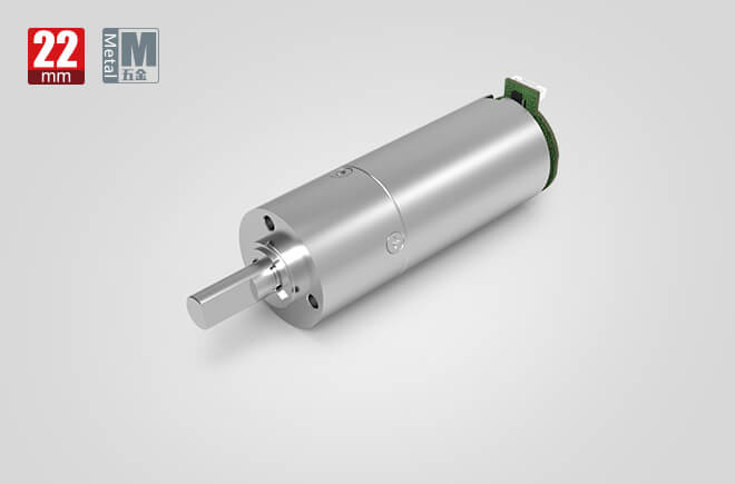
A robot speed reducer (precision reducer) is the gear assembly mounted between a servo motor and a robot joint. Its job is to take the motor’s high-speed, low-torque rotation and convert it into the joint’s low-speed, high-torque motion — with the precision, stiffness, and backlash control a robot demands. Industrial reducers are purpose-built precision components (harmonic, RV/cycloidal, planetary), not the coarse industrial gearboxes used elsewhere; a normal gearbox has too much backlash, too little stiffness, and cannot survive a robot’s millions of repeated cycles.
In short, the reducer is the adapter between a motor that is born to spin and a joint that must push, hold, and position. It is one of the three core components of an industrial robot (along with the servo motor and the controller), and typically accounts for 30–40% of the robot’s bill of materials.
The Servo Motor’s Built-In Mismatch
A standard servo motor is specified for speed, not force:
- High speed, low torque: rated 3,000–6,000 rpm but only a few N·m of output torque (small frameless motors deliver well under 1 N·m).
- Very small rotor inertia: fast to respond, but weak against disturbance — it shakes, drifts on start/stop, and cannot hold the arm’s weight when power is removed.
A robot joint needs the opposite: a few rpm of motion and hundreds to thousands of N·m of torque. The reducer bridges that gap.
Why a Robotic Arm Needs One: 5 Engineering Reasons
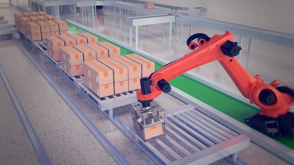
Every articulated and collaborative robot places a precision reducer at (almost) every axis. Here is exactly what it contributes.
1. Torque multiplication (the core function)
The universal rule of gearing: drop the speed by the ratio, multiply the torque by the same ratio. A 1 N·m servo motor behind a 100:1 reducer delivers ~100 N·m at the joint — without needing a massive, expensive high-torque motor, and while keeping the robot body compact.
2. Speed reduction to a usable range
A motor at thousands of rpm would whip the arm around uncontrollably. The reducer brings joint speed down to the few rpm a robot actually needs for smooth, precise motion.
3. Positioning error is divided by the ratio
A small angular error at the motor becomes a much smaller error at the joint. At 100:1, a 0.1° motor-control error becomes just 0.001° at the output — this is what enables the ±0.01 mm repeatability of modern industrial robots.
4. Inertia matching and stability
Reflecting the load inertia back through the reducer scales it by 1/i². The right ratio makes the reflected inertia match the motor’s rotor inertia, so the joint accelerates and stops crisply instead of oscillating. Get it wrong and the arm jitters and overshoots.
5. Stiffness, shock buffering, and holding
The reducer adds torsional stiffness, absorbs collision/load shocks that would otherwise destroy the motor and encoder, and provides enough transmission drag to hold the arm’s pose (and often self-lock) when power is cut — a critical safety function.
What Goes Wrong Without a Reducer
- Not enough force — the motor cannot even lift the arm, let alone a payload.
- Runaway motion — too fast to program, weld, or pick accurately.
- Accuracy destroyed — end-effector error too large for any precision task.
- Jitter and drift — unstable trajectories, uneven welds, misaligned picks.
- Safety hazard — the arm drops under its own weight when power fails.
- Motor burnout — repeated shock loads overheat and kill the servo.
How a Robot Speed Reducer Works: Step-by-Step
Take a strain-wave (harmonic) reducer as the reference; RV and planetary follow the same “convert speed to torque” logic with different internal geometry.
- The servo motor spins the input. High speed (thousands of rpm), low torque, feeds the reducer’s input shaft.
- The wave generator (input) deforms the flexspline. An elliptical cam with a flexible bearing presses the thin-walled flexspline into the rigid circular spline — but only engages over a short arc.
- The flexspline has two fewer teeth than the circular spline. As the wave generator rotates one turn, the flexspline (output) shifts by exactly two teeth in the opposite direction — that tooth difference is what creates the huge reduction ratio in a single stage.
- Speed drops, torque rises. Output speed = input speed ÷ ratio; output torque = input torque × ratio × efficiency. The same physics applies to an RV reducer (planetary stage + cycloidal disc) and a planetary reducer (sun–planet–ring).
- Position error is divided. Any input angular error is reduced by the ratio at the output, so the joint lands precisely where the controller commands.
- Stiffness holds the pose. The engaged teeth/rollers provide torsional stiffness; when the motor stops, the transmission drag (and, for some types, self-locking) holds the joint against gravity and load.
Types of Robot Speed Reducers Compared
Robot arms almost never use one reducer type everywhere. The reducer is matched to the joint’s load, speed, and precision need.
| Reducer type | Typical robot axis | Key strength | Best-fit application |
|---|---|---|---|
| RV / cycloidal | Base, shoulder, elbow (axes 1–3) | Very high stiffness, overload, long life | Heavy payload: welding, palletizing, >200 kg arms |
| Harmonic (strain-wave) | Wrist, forearm, hand (axes 4–6) | Zero backlash, light, huge single-stage ratio | Precision assembly, cobots, humanoid joints |
| Planetary | SCARA, AGV, light axes | High efficiency, robust, low cost | High-throughput pick/place, horizontal motion |
| Worm gear | Specialty / locking axes | Right-angle, self-locking | Where the joint must hold position without a brake |
The division of labor is clear: base and heavy arm joints use RV for rigidity and shock load; wrists and light/compact joints use harmonic for zero backlash and weight; SCARA and mobile platforms use planetary for efficiency and cost.
Harmonic vs. RV vs. Planetary: The Numbers
| Parameter | Harmonic | RV (cycloidal) | Planetary |
|---|---|---|---|
| Single-stage ratio | 50:1 – 320:1 | 30:1 – 300:1 | 3:1 – 10:1 (multi-stage higher) |
| Backlash | ≤ 30 arcsec (premium ≤ 10 arcsec) | ≤ 1 arcmin | ≤ 3 arcmin |
| Torsional stiffness | Lower (flexspline compliance) | Very high (>300 N·m/arcmin) | High |
| Efficiency | 65–90% (rises with ratio) | 80–92% | > 97% |
| Torque density | High (CSD ~150 N·m/kg) | Very high (RV-110N ~320 N·m/kg) | Medium |
| Limiting factor | Flexspline fatigue life | Bearing / pin life, size | Backlash, package size |
| Repeatability enabled | ±0.01 – 0.02 mm | ±0.02 – 0.05 mm | ±0.05 – 0.1 mm |
Backlash (the lost motion when reversing direction) is the single biggest accuracy driver. Harmonic and RV keep it near-zero; a standard gearbox cannot, which is why robots pay a premium for precision reducers.
Robot Speed Reducer Engineering Data: Formulas & Limits
These are the equations an integration engineer actually uses. All are consistent with IEC 60034 (motor) and AGMA / ISO gear-rating practice.
1. Reduction ratio
i = nin / nout — input (motor) speed ÷ output (joint) speed. A 3,000 rpm motor driving a 30 rpm wrist gives i = 100.
2. Output torque
Tout = Tin × i × η — torque scales by ratio and efficiency. A 1 N·m servo with a 100:1 reducer at 85% η delivers ~85 N·m at the joint.
3. Output speed
ωout = ωin / i — speed divides by the ratio.
4. Reflected (inertia-matched) load
Jref = Jload / i² — the load inertia seen at the motor shrinks by the square of the ratio. This is why a reducer stabilizes a light-rotor motor.
5. Inertia-matching rule of thumb
Keep Jref / Jmotor ≤ 5 for best dynamic response (≤ 10 is generally acceptable). If the ratio is too low, the reflected inertia dominates and the joint oscillates; if too high, the motor runs in an inefficient, low-torque corner.
6. Position error divided by ratio
θjoint_error = θmotor_error / i. The reducer turns a modest motor-control error into a tiny joint error — the foundation of robot repeatability (ISO 9283 pose accuracy/repeatability).
Worked example — sizing a wrist joint
A wrist must deliver 80 N·m continuously at 30 rpm. We pick a 1.2 N·m servo (rated 3,000 rpm) and a harmonic reducer. Required ratio i = 3000 / 30 = 100. Needed efficiency η = Tout / (Tin × i) = 80 / (1.2 × 100) = 0.67 — so we need a unit rated ≥ 67% efficient at 100:1 (typical for harmonic), and we confirm the rated torque and the flexspline fatigue life against the duty cycle. The 0.1° motor error becomes 0.001° at the wrist.
Market context (why this matters commercially)
The global robot joint precision-reducer market reached USD 4.1 billion in 2025 and is projected at USD 11.5 billion by 2032 (CAGR 15.8%). By type, RV holds ~38.6%, harmonic ~31.2%, planetary ~20.0%; articulated robots drive ~65% of demand. Nabtesco leads RV, Harmonic Drive leads harmonic, and Chinese makers (Leaderdrive / 绿的谐波, Shuanghuan, etc.) are rapidly gaining share — relevant if you are sourcing or building robot drivetrains.
Best Reducer Choices by Robot & Joint
| Robot / joint | Preferred reducer | Why |
|---|---|---|
| Industrial base / shoulder / elbow (axes 1–3) | RV / cycloidal | High stiffness, shock load, long life under heavy payload |
| Wrist & forearm (axes 4–6) | Harmonic | Zero backlash, light, compact, high ratio in one stage |
| Collaborative robots (cobots) | Harmonic | Lightweight joints, precise force control, safe human contact |
| SCARA robots | Planetary | Fast indexing, good backlash, cost-effective |
| Humanoid robots | Harmonic / precision cycloidal | Compact, high torque density for animated joints |
| Surgical / lab automation | Magnetically-encoded harmonic | Ultra-low vibration, clean (no oil mist), micron precision |
| Delta (high-speed pick) | Planetary | Efficiency and control at high cycle rates |
For the motor side, pair these reducers with BLDC or stepper motors sized to the reflected load — not to the raw joint torque.
How to Select a Robot Speed Reducer: Step-by-Step
- Locate the joint. Base/shoulder/elbow under load → RV. Wrist/forearm/light → harmonic. SCARA/AGV → planetary. This single decision settles 80% of the spec.
- Define output torque and speed. From the payload, reach, and cycle time: Tout (continuous + peak) and nout.
- Pick the ratio. i = nmotor / nout. Confirm the motor’s rated speed lands in its efficient band after division.
- Back-check motor torque. Tin = Tout / (i × η). The motor must deliver Tin comfortably within its continuous rating.
- Run the inertia match. Compute Jref = Jload / i² and verify Jref / Jmotor ≤ 5 (≤ 10 acceptable). If not, change i or motor size.
- Set the accuracy target. Need micron repeatability? Choose harmonic (≤30 arcsec) or RV (≤1 arcmin). Backlash, not ratio, limits your pose accuracy per ISO 9283.
- Confirm stiffness vs. shock. Heavy or impact-prone axes need RV’s torsional rigidity; compliant harmonic flexsplines fatigue under sustained overload.
- Check duty, temperature, and life. Validate rated torque against the duty cycle, keep lubrication in range (typically −10 to 80 °C for grease-packed units), and confirm L10 / flexspline fatigue life exceeds the required cycle count.
Common Robot Reducer Engineering Mistakes
- Sizing on torque only, ignoring inertia. A reducer that meets peak torque but gives Jref/Jmotor > 10 makes the joint oscillate and overshoot. Always run the inertia match.
- Ignoring backlash’s effect on accuracy. A standard gearbox (not a precision reducer) has too much lost motion; the arm repeats poorly on reversals. Use harmonic/RV where repeatability matters.
- Ratio too high, motor in a bad corner. Over-reducing forces the motor to run at very low speed/high current, wasting torque and heating. Re-check Tin lands in the efficient band.
- Wrong stiffness for the load. Putting a compliant harmonic on a heavy, shock-loaded axis causes flexspline fatigue and vibration; that axis needs RV rigidity.
- Poor thermal / lubrication management. Grease-packed harmonic and RV units have a temperature window; overheating accelerates flexspline fatigue and bearing wear.
- Substituting a coarse gearbox. A cheap industrial gearbox cannot survive millions of robot cycles and lacks the backlash/stiffness control — it is not a precision reducer.
Robot Reducer Troubleshooting: Problem → Cause → Solution
| Problem | Likely cause | Solution |
|---|---|---|
| Joint jitter / overshoot | Inertia mismatch (Jref/Jmotor > 10), wrong ratio | Recompute inertia match; adjust ratio or motor size |
| Poor repeatability on reversal | Excess backlash (coarse gearbox or worn unit) | Use/precision harmonic or RV; inspect flexspline/wear |
| Overheating | Overload, poor lubrication, above temp window | Reduce load, check grease/temperature, add cooling |
| Noise / vibration | Low stiffness for load, misalignment, bearing wear | Use rigid RV, re-align, replace bearings |
| Backlash growing over time | Harmonic flexspline fatigue, RV pin wear | Replace flexspline / reducer; verify duty cycle |
| Accuracy drifting | Thermal growth, accumulated transmission error | Re-calibrate, monitor operating temperature |
| Oil/grease leakage | Failed shaft seal (RV / lubricated types) | Replace seal, re-lubricate to spec |
| Arm drops when powered off | No holding / self-lock, brake not engaged | Add holding brake; verify reducer holding torque |
Frequently Asked Questions
Can a robotic arm run without a speed reducer?
In practice, no — for servo-driven articulated arms. A direct-drive motor would be too fast, too weak, too jittery, and would fall under its own weight when power is cut. A few specialized direct-drive robots exist for very specific low-ratio axes, but the vast majority use a precision reducer at every joint.
Harmonic or RV — which is better for a robot?
Neither is universally “better”; they are assigned by axis. RV (cycloidal) wins for base/shoulder/elbow joints that need stiffness, shock load, and long life under heavy payload. Harmonic wins for wrist/forearm/light joints that need zero backlash, low weight, and a huge single-stage ratio. Many arms use both.
What reduction ratio does a robotic arm use?
It varies by axis and motor speed: commonly 30:1 to 320:1. A 3,000 rpm servo on a 30 rpm wrist needs i = 100. The ratio is set by the required output speed, then checked against motor torque, inertia match, and efficiency.
What is backlash and why does it matter?
Backlash is the lost motion (dead zone) when a reducer reverses direction. It directly limits repeatability. Precision reducers keep it tiny — harmonic ≤ 30 arcsec, RV ≤ 1 arcmin — whereas a standard gearbox has far too much for robot accuracy.
How do I match motor inertia to the reducer?
Compute the load inertia reflected to the motor: Jref = Jload / i². Keep Jref / Jmotor ≤ 5 for best response (≤ 10 is acceptable). This stabilizes acceleration and eliminates oscillation — it is as important as the torque check.
How long do robot reducers last?
RV and planetary units are rated in L10 bearing life and survive millions of cycles; harmonic life is set by flexspline fatigue and depends on torque, duty, and temperature — premium units are qualified for 10,000–15,000+ hours. Proper sizing, lubrication, and staying within the temperature window are what actually deliver that life.
Why Choose Greensky for Robot Drive & Custom Reducer-Motor Units?
When a standard catalog reducer fits, the big brands are fine. When you are building a robot drivetrain and need the motor + precision reducer as one engineered, inertia-matched assembly, Greensky Power is the OEM/ODM partner. Since 2011 we have built BLDC, stepper, and brushed DC motors matched to harmonic, planetary, and worm reducers for automation and robotics customers in 50+ countries.
- Inertia-matched design: we size the motor and ratio together so Jref/Jmotor lands in the stable band — not just peak torque.
- Integrated joint modules: motor + reducer + encoder supplied as one concentric unit, no adapter guesswork, correct flange every time.
- Right reducer per axis: harmonic for zero-backlash wrists, planetary for efficiency, worm where self-holding matters.
- Thermal-aware sizing: rated to continuous duty within the temperature window, so flexspline/bearing life is real, not nominal.
- Flexible MOQ & lead time: from prototype to mass production.
- Standards practice: motors built to IEC 60034 / NEMA MG 1; ISO and CE certified.
References
- ISO 9283, Manipulating industrial robots — Performance criteria and related test methods (pose accuracy / repeatability). https://www.iso.org/standard/57338.html
- ISO 10218-1, Robots and robotic devices — Safety requirements for industrial robots. https://www.iso.org/standard/74351.html
- IEC 60204-1, Safety of machinery — Electrical equipment of machines. https://webstore.iec.ch/publication/2606
- IEC 60034-1, Rotating electrical machines — Rating and performance. https://webstore.iec.ch/publication/60034-1
- NEMA MG 1, Motors and Generators. https://www.nema.org/standards/view/motors-and-generators
- AGMA 6000 / ANSI/AGMA 2000, Gear rating and inspection practice. https://www.agma.org/standards/
- SKF, Bearing rating life (L10), mounting & lubrication guidance. https://www.skf.com/group/support/engineering-tools/bearing-calculator
- Nabtesco, RV reducers — technical documentation & ratings. https://www.nabtesco.com/en/
- Harmonic Drive (Harmonic Drive Systems), Strain wave gearing technology notes. https://www.harmonicdrive.net/learning
- U.S. Department of Energy, Motor & Drive Systems — Energy Efficiency. https://www.energy.gov/eere/motors
