
Quick Answer
A 12V 1000 RPM DC gear motor is a small (commonly 20–38 mm diameter, below 50 W) brushed or brushless DC motor bolted to a planetary gearbox, trading speed for torque at the output shaft. The “1000 RPM” is the top of the output-speed range (about 2.4–1000 RPM for this family); the real loaded speed is lower. Size it from the load: pick the reduction ratio from the required output speed, then verify torque with T out = T motor × ratio × η. One thing buyers miss: a motor this small carries no IE efficiency class — IEC 60034-30-1 starts at 0.12 kW and excludes DC motors, so it is sized by torque, speed and runtime, not an energy badge.
What Is a 12V 1000 RPM DC Gear Motor?
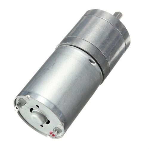
A 12V 1000 RPM DC gear motor is a DC motor — the rotating electrical machine — married to a reduction gearbox in one housing. The motor alone spins fast (typically 3,000–6,000 RPM at 12 V no-load) but with little torque; the gearbox slows the shaft and multiplies torque. The result is a compact, low-voltage package that delivers usable torque at a controlled, low speed — exactly what battery-powered and low-voltage devices need.
In the “1000 RPM” family this is a micro planetary gear motor: a 20 mm-class planetary stage, a 12 V winding, and a rated output below 50 W. The product spans small-power brushed DC and brushless DC builds. The name “1000 RPM” describes the maximum output speed in the ratio set, not a fixed operating point: with ratios of 5 / 25 / 125 / 625:1 the same core motor yields output speeds from roughly 1000 RPM (5:1) down to a few RPM (625:1).
Note: The original thin page titled this “DC 12V 1000rpm gear motor Specifications” and listed it as a 20 mm planetary unit with plastic or powder-metallurgy metal gears, 12 V, no-load current ~220 mA, load speed 2.4–1000 RPM and ratios 5/25/125/625:1. Those figures are preserved and corrected below, with the engineering behind them filled in.
How a DC Gear Motor Works
The unit is two sub-assemblies in series, and understanding both is the difference between a sizing that works and one that burns out:
- The motor converts 12 V DC into rotation. In a brushed unit, a commutator and carbon brushes switch the winding current; in a brushless DC motor an electronic controller commutates it. The motor sets the input speed and torque.
- The planetary gearbox takes that fast, low-torque spin and reduces it. A planetary set has a central sun gear on the motor shaft, 3–4 planet gears on a carrier, meshing with an outer ring gear. Because load is shared across several planet gears, a planetary stage is compact and torque-dense — ideal for a 20 mm can.
- Stages stack the ratio. One planetary stage gives roughly 3.5–5:1. Two stages ~12–25:1, three ~43–125:1, four ~150–625:1. The 5/25/125/625:1 set on this product is exactly 1 / 2 / 3 / 4 stages at the typical integer points.
- Output. The carrier (or ring, if the ring is fixed) drives the output shaft at low speed and high torque, in the same rotation direction as the motor for planetary sets (unlike odd-stage spur boxes, whose direction reverses).
Back-driving and holding. A planetary gearbox is generally not self-locking — with the motor off, a load can spin the output back through the gears and motor. If your mechanism must hold position without power (a lift, a hatch, a vertical axis), choose a worm stage, a brake option, or rely on the controller’s hold torque. Forgetting this is a frequent miss in vertical-axis designs.
For a deeper walk-through of the reduction principle, our how a planetary gearbox works guide covers sun/planet/ring geometry, and what a DC geared motor is used for maps the format to applications.
Reading the Datasheet: Key Parameters
A micro gear motor datasheet is short, so every line matters. Here is what each parameter on this 12V 1000 RPM family actually controls:
| Parameter | What it means | Typical for this 20 mm / 12 V class |
|---|---|---|
| Voltage | Nominal supply. 12 V suits automotive, lead-acid and 3-cell Li-ion packs. | 12 V (custom 3–24 V) |
| Rated power | Mechanical output the motor-gearbox can sustain. Below 50 W puts it in the “micro” band. | 0.5–5 W at the shaft |
| No-load speed | Shaft speed at 12 V with zero load. The 1000 RPM figure sits here at low ratio. | ~6000 RPM (motor) → up to ~1000 RPM (5:1) |
| Load / rated speed | Shaft speed under rated torque. Usually ~80% of no-load for the same ratio. | 2.4–1000 RPM (ratio-dependent) |
| Reduction ratio | Motor speed ÷ output speed. Sets speed and torque together. | 5 / 25 / 125 / 625:1 |
| No-load current | Current to spin the bare motor. A wear and standby-drain hint. | ~70–220 mA (spec ~220 mA) |
| Rated / stall torque | Sustainable vs shaft-locked torque. Never size to stall. | Output 0.1–2 N·m by ratio |
| Gear material | Plastic (quiet, cheap) vs powder-metallurgy metal (load, rigidity). | Plastic or sintered metal |
| Diameter | Gearbox OD; the binding constraint in most devices. | Φ20 mm |
The single most misread line is no-load vs rated speed. Quoting the 1000 RPM no-load number as the operating speed overstates real speed by 20% or more once the load is on — and by far more at high ratio. Always size from the loaded speed.
Planetary, Spur or Worm — and Plastic vs Metal Gears
Not every micro gear motor is planetary. Within the small-DC class three gear systems compete, and the choice drives cost, noise and torque density:
| Gear system | Torque density | Backlash | Noise | Best fit |
|---|---|---|---|---|
| Planetary | High — load shared across planets | Low (<2.5° typical) | Low | Precision, robotics, medical, 20 mm cans |
| Spur | Medium | Medium | Higher (esp. at speed) | Lowest cost, vending, appliances |
| Worm | High at low speed | Medium | Medium | Self-locking, right-angle drives |
On gear material, this product offers both plastic and powder-metallurgy metal:
| Gear material | Pros | Cons | Use when |
|---|---|---|---|
| Plastic (POM/nylon) | Quiet, cheap, self-lubricating | Lower load/temp limit, wears faster | Light load, indoor, cost-driven |
| Powder metallurgy metal | High torque, rigid, durable, net-shape (>97% material use) | Costlier, slightly noisier | Continuous duty, higher torque, automotive |
Single-stage metal planetary efficiency commonly reaches 85–95%; spur pairs run ~91% each. The aggregate gearbox efficiency is the product across stages, so a 4-stage 625:1 box loses more than a 1-stage 5:1 box. Our planetary gearbox types and speed-reducer types pages go deeper, and micro gear-reducer problems covers wear modes.
Gearbox Efficiency and the Torque Formula
The gearbox does not create torque — it trades speed for torque and keeps most of it. Two equations size every micro gear motor:
| Quantity | Formula | Note |
|---|---|---|
| Reduction ratio | i = n motor ÷ n out | Pick from required output speed |
| Output torque | T out = T motor × i × η | η = gearbox efficiency |
| Output speed | n out = n motor ÷ i × (load factor) | Load factor ~0.8 vs no-load |
| Input current | I = T motor ÷ K t + I nl | K t = torque constant |
Ignoring η is the classic error: a 50:1 box at 75% efficiency multiplies motor torque by 37.5, not 50 — overstating output by 25%. Per-stage efficiency stacks as a product, so a 4-stage 625:1 metal planetary at ~0.90 per stage lands near η ≈ 0.66 overall. Treat the ratio as a speed changer and η as the tax you pay for the torque.
Worked numbers appear in the sizing example below. For the general method see our motor torque calculation hub and speed-reducer selection guide.
Brushed vs Brushless in a 12V Micro Gear Motor
The same 20 mm planetary can ship with a brushed or a brushless DC core. The trade is life and noise versus cost and simplicity:
| Attribute | Brushed DC (original spec) | Brushless DC (BLDC) |
|---|---|---|
| Commutation | Mechanical brushes + commutator | Electronic controller |
| Life | ~1,000–3,000 h (brush wear) | 10,000+ h |
| Noise / EMI | Higher (sparking) | Lower |
| Cost | Lower | Higher (needs controller ) |
| Best duty | Intermittent, cost-driven | Continuous, quiet, long-life |
For 24/7 or medical use, brushless wins on life; for a cheap toy or one-shot actuator, brushed is fine. The brush vs brushless and 12V brushless advantages pages cover the split, and why add a gearbox explains when reduction pays off.
Why a 12V 1000 RPM Gear Motor Has No IE Rating
Buyers often ask “what IE class is this gear motor?” For this product the honest answer is none — and that is correct, not a gap. Two clauses in IEC 60034-30-1 (the IE-code standard) exclude it:
| Exclusion in IEC 60034-30-1:2025 | Why it hits this motor |
|---|---|
| Rated power from 0.12 kW to 1000 kW | This unit is ≤50 W (0.05 kW) — below the 120 W floor |
| “Motors with mechanical commutators (such as DC motors)” | Brushed builds use a commutator; BLDC is converter-fed DC |
| Line-operated 50/60 Hz AC only | This is a 12 V DC unit, not mains AC |
So the right framework is not an IE badge but torque, speed, duty cycle and runtime — exactly the sizing method above. This is the same reason our motor efficiency class guide notes BLDC itself carries no IE class: the IE code is an AC-line-industrial-motor system, and small DC gear motors sit entirely outside it. Sizing by the numbers beats chasing a label that was never defined for this class.
Best Applications
The 12V 1000 RPM micro planetary gear motor shows up wherever a small, quiet, low-voltage actuator must move a light load precisely. Typical fits:
- Smart home — electric curtains and blinds, smart locks, automated vents. See the broader appliance motor list.
- Automotive — door-lock actuators, retractable mirrors, antenna rotators, tailgate pushers. Tie to gate motors for heavier variants.
- Electronics & kiosks — vending machines, ATM carousels, bill dispensers, rotating advertising displays (the worked example below).
- Antenna drive — RV/camper and marine antenna rotators needing slow, steady azimuth motion.
- Medical — infusion and cleaning pumps where quiet, repeatable motion matters; compare with pump motors.
- Robotics / AGV — joint and accessory actuators; see AGV motor solutions and popular BLDC markets.
For battery devices, runtime is set by the draw from the controller and the duty cycle: a 0.5 A average at 12 V is ~6 W, so a 2 Ah pack gives roughly 4 h of continuous run, less with starts and stalls. Match the IP rating (IP54–IP67) and gear material to the environment — our gearbox-need note covers when reduction pays off.
How to Select a 12V 1000 RPM Gear Motor: Step-by-Step
- Fix the load. Define required output torque (from mass, radius, friction) and output speed, plus axial/radial load and duty cycle.
- Pick the drive motor. Brushed for cost, brushless for life and quiet. Stay at 12 V unless the pack demands 24 V.
- Derive the ratio.
i = n motor ÷ n out, then choose the nearest standard ratio (5/25/125/625:1 here) and check the resulting speed. - Verify torque with efficiency.
T motor = T out ÷ (i × η); the motor must sustain that at the operating speed. - Check current and heat.
I = T motor ÷ K t + I nl; confirm the 12 V supply and duty cycle keep windings within class. - Confirm the interface. Shaft type, mounting, gear material (plastic vs metal), IP rating and any custom need.
This loop is the micro analogue of our full industrial motor selection guide.
Worked Sizing Example: 12V Gear Motor for a Rotating Display
Requirement. A battery-powered rotating advertising display (trade-show turntable) must turn a 120 mm-radius disc carrying 1.5 kg of product at one revolution per 5 s (12 RPM), 360° continuous.
1. Load torque. Model the load as bearing friction: T load ≈ μ × m × g × r with μ = 0.05. That gives 0.05 × 1.5 × 9.81 × 0.12 ≈ 0.088 N·m. Apply a 2× safety margin → design T_out = 0.18 N·m.
2. Speed and ratio. Required output speed 12 RPM. Pick a 12 V micro motor with no-load speed 5000 RPM. Ideal ratio i = 5000 ÷ 12 ≈ 417:1. The standard set offers 125:1 or 625:1; 125:1 gives a faster 40 RPM (acceptable), 625:1 gives 8 RPM. Choose 125:1 (3-stage metal planetary, η ≈ 0.86).
3. Verify torque. T motor = 0.18 ÷ (125 × 0.86) = 0.00167 N·m = 1.67 mN·m. A 12 V micro motor rated ~4 mN·m clears this with margin. ✓
4. Current and power. With torque constant K_t ≈ 4 mN·m/A and no-load current 90 mA: I = 1.67 ÷ 4 + 0.09 ≈ 0.51 A. At 12 V that is ~6.1 W electrical. Output power P out = T out × ω = 0.18 × (40 × 2π/60) ≈ 0.75 W. Combined motor-plus-gearbox efficiency ~12% — normal for a small gear motor where most loss is in the box and iron.
Note: Counter-intuitive takeaway. The “1000 RPM” motor delivers only ~40 RPM at the shaft under a real load — because the name is the high end of a ratio family, not your operating point. And it carries no IE class, because at ≤50 W DC the standard simply doesn’t apply. Size by torque and runtime, not by the headline number or an energy badge.
Common Engineering Mistakes
- Sizing from no-load speed. Use loaded speed for the ratio, or the output runs slower than expected.
- Ignoring gearbox efficiency. Treating the ratio as pure torque gain overstates output by 20–35% across stages.
- Quoting the 1000 RPM name as operating speed. It is the 5:1 no-load extreme; loaded and high-ratio speeds are far lower.
- Allowing stall. A jammed load draws 5–10× current and burns the winding or strips gears.
- Overlooking axial/radial load. Exceeding the gearbox rating shortens bearing life; see gearbox wear causes.
- Choosing brushed for 24/7 duty. Brush wear ends it in 1,000–3,000 h; brushless is the right call.
- Asking for an IE class. This class has none — size by torque, speed and runtime instead (see above).
Troubleshooting
| Problem | Likely cause | Solution |
|---|---|---|
| Output slower than expected | Ratio set from no-load speed | Recompute from loaded speed; adjust ratio |
| Motor stalls / won’t push load | Torque under-estimated or η ignored | Verify T = T motor × i × η ; raise ratio or motor |
| Motor burns out | Stall / overload current 5–10× | Add current limit; clear jam; check duty |
| Noisy / vibrating | Worn gear or bearing, poor mesh | Re-grease; inspect teeth; respect load ( noise reduction ) |
| Short life (brushed) | Brush wear in continuous duty | Switch to brushless for 24/7 |
| Position drift (precision apps) | Backlash too high | Use low-backlash planetary stage |
Why Choose Greensky Power
Greensky Power designs and builds DC planetary gear motors, BLDC planetary gear motors and brushless gear motors in the 20–100 mm class, with plastic or powder-metallurgy metal gears and full ratio coverage including the 5/25/125/625:1 set. Every unit is built to a test standard so the shipped torque and speed match the datasheet. For volume or non-standard specs — shaft, flange, ratio, encoder, brake, IP rating — our custom BLDC and OEM routes deliver documented, repeatable builds.
Related Resources
- What Is a DC Motor? — the machine behind the gearbox
- Gearbox Basics — reduction principles
- How a Planetary Gearbox Works — sun/planet/ring geometry
- What a DC Geared Motor Is Used For
- Motor Torque Calculation — the sizing hub
- Speed-Reducer Selection
- Brushed DC Motors · Brushless DC Motors
- Motor Efficiency Classes (and why small DC has none)
- 24V Brushless DC Motor Guide — the 24 V cousin
- Custom Electric Motors · Gear Motor Manufacturers in China
References and Standards
- IEC 60034-1:2022, Rotating electrical machines — Part 1: Rating and performance. — webstore.iec.ch
- IEC 60034-30-1:2025, Efficiency classes of line-operated AC motors (IE code) — scope 0.12 kW–1000 kW, excludes DC/commutator motors. — webstore.iec.ch
- IEC 60529, Degrees of protection (IP code). — iec.ch
- ISO 9001, Quality management systems. — iso.org
- ANSI/NEMA MG 1, Motors and Generators. — nema.org
- U.S. DOE, Motor systems — efficiency and load. — energy.gov
- IEA, Electric motors (efficiency landscape). — iea.org
- SKF, Bearing failures and their causes. — skf.com
- Siemens, SIMOTICS electric motors. — siemens.com
- maxon, EC (brushless) technology. — maxongroup.com
- Faulhaber, Drive system know-how. — faulhaber.com
- AGMA, Gear standards and service-factor method. — agma.org
- Tsubakimoto, Gearmotor selection technical data (service factor). — tsubakimoto.co.jp
- IEEE Xplore, Micro motor efficiency modeling. — ieeexplore.ieee.org
FAQ
What does “1000 RPM” mean on a 12V DC gear motor?
It is the maximum output speed in the ratio set — roughly 1000 RPM at the 5:1 ratio, falling to a few RPM at 625:1. The real loaded speed is lower, about 80% of the no-load figure for the same ratio, so never quote 1000 RPM as your operating point.
How do I calculate output torque from the reduction ratio?
Use T out = T motor × ratio × η, where η is gearbox efficiency (about 0.66–0.86 for a multi-stage metal planetary). Work backwards to the motor torque you need: T motor = T out ÷ (ratio × η), then confirm the motor sustains it at speed.
What is the difference between brushed and brushless 12V gear motors?
Brushed is simpler and cheaper but wears out in ~1,000–3,000 h. Brushless lasts 10,000+ h, runs quieter and needs an electronic controller. Pick brushed for intermittent, cost-driven jobs; brushless for continuous, quiet or medical duty.
What IE efficiency class is a 12V 1000 RPM gear motor?
None. IEC 60034-30-1 starts at 0.12 kW (120 W) and excludes DC motors with mechanical commutators; this unit is ≤50 W and 12 V DC. Size it by torque, speed and runtime — not an IE badge that the standard never defined for this class.
Plastic or metal (powder metallurgy) gears — which should I choose?
Plastic is quiet and cheap for light, indoor, intermittent loads. Sintered metal carries higher torque, is more rigid and lasts longer in continuous or automotive duty. The metal planetary also reaches higher single-stage efficiency (85–95%).
Can I run a 12V gear motor at 24V for more speed?
Not safely. Doubling voltage roughly doubles speed and current, pushes windings past their thermal class and shortens life; the gearbox rating is unchanged. If you need 24 V, choose a 24 V-wound unit — see our 24V BLDC guide — rather than over-driving a 12 V part.
