
10 Reasons Why We Need an Electric Motor with Gearbox
Quick Answer
Tₙ = Tₔ × i × η), and—less obviously—the load inertia the motor must accelerate falls by the square of the ratio (Jₙ = Jₚ / i²). The ten reasons below all follow from these two numbers, plus the protection, cost, and packaging benefits of pairing motor and gearbox into a single geared motor. The result is lower system cost, better start/stop control, and a motor that runs in its efficient band instead of crawling near stall.Contents
- What Is a Geared Motor (Motor + Gearbox)?
- How a Gearbox Changes Speed and Torque
- The 10 Reasons to Use a Motor with a Gearbox
- Engineering Data: Efficiency, Temperature, Torque, Inertia
- Gearbox Type Comparison
- Best Applications for Geared Motors
- How to Select a Geared Motor (Worked Example)
- Common Engineering Mistakes
- Troubleshooting
- FAQ
- Why Choose Greensky Power?
What Is a Geared Motor (Motor + Gearbox)?
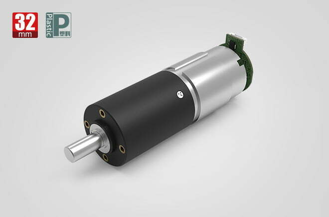
A geared motor is an electric motor and a speed reducer built or mated into one integrated drive. The motor contributes high speed at low torque; the gearbox converts that into low speed at high torque through a gear train (spur, planetary, worm, helical, or bevel). The pairing is so common it has its own name—a gear motor—because the two components solve each other’s weakness.
The distinction from a bare motor matters. A bare motor is specified by speed and torque at one operating point; a geared motor adds a reduction ratio that shifts that point to wherever the application needs it. This single added degree of freedom is what makes the combination indispensable in automation, robotics, medical devices, and appliances. For the boundary between the two components, see our gearbox vs. gear motor explainer; for when to skip the gearbox entirely, see the direct-drive vs. gear-motor comparison.
How a Gearbox Changes Speed and Torque
A reducer does two things at once, bound together by energy conservation: it divides speed and multiplies torque. Every reason to use one traces back to this trade plus its second-order effect on inertia.
The Speed–Torque Trade
- Reduction ratio:
i = nₔ / nₙ(input speed ÷ output speed) - Output torque (ideal):
Tₙ = Tₔ × i - Output torque (real):
Tₙ = Tₔ × i × η(gearbox efficiency) - Output speed:
nₙ = nₔ / i - Output power:
Pₙ = (Tₙ × nₙ) / 9550(T in N·m, n in rpm, P in kW)
A 20:1 reducer turns a 3,000 rpm motor into a 150 rpm output while multiplying torque by (up to) 20×, minus friction losses. This is why a 100 W motor behind a reducer can move a load that would otherwise demand a far larger motor. The motor-side math is covered in our torque calculation guide.
Inertia Reduction — the Squared Rule
The quieter but more powerful effect is on inertia. Load inertia reflected to the motor is divided by the square of the ratio:
- Reflected inertia:
Jₙ = Jₚ / i²
A 20:1 reducer therefore cuts the inertia the motor must accelerate by 400×, not 20×. This is why a small servo plus a gearbox can start and stop crisply where a direct-drive motor of the same torque would feel sluggish—the motor is accelerating a tiny reflected inertia. It is the single most under-appreciated reason to add a reducer, and it dominates in positioning and start/stop applications.
The 10 Reasons to Use a Motor with a Gearbox
Here are the ten engineering reasons, each tied to the physics above rather than to a marketing claim.
- Torque multiplication. The reducer multiplies output torque by (roughly) the ratio, so a small, low-cost motor drives a heavy load.
Tₙ = Tₔ × i × η. - Speed matching. Loads rarely need 3,000 rpm. The reducer steps motor speed down to the exact output speed the machine needs (a conveyor, valve, or lead screw).
- Inertia reduction. Reflected inertia falls by the square of the ratio (
Jₙ = Jₚ / i²), giving crisp start/stop, better servo tuning, and faster settling. - Overload protection for the motor. Overload torque seen by the motor is divided by the ratio; the gearbox absorbs the shock, and its (cheaper) teeth fail before the motor windings.
- Lower system cost. A small motor + gearbox almost always costs less than the large, high-pole torque motor needed to hit the same torque at low speed.
- Lower current draw. Because the motor runs fast and lightly loaded rather than near stall, input current falls for the same output torque, reducing heat and power-supply sizing.
- Compact package / high torque density. Integrating motor and reducer into one gearbox saves volume versus a direct-drive torque motor of equal rating.
- Precise speed and position control. A defined ratio plus controlled backlash (from a precision planetary or harmonic stage) gives repeatable positioning for robots, optics, and valves.
- Modular, low-cost maintenance. When the reducer fails under extreme overload, you replace its gears or bearings—not the motor—at a fraction of the cost and downtime.
- Application versatility. Swapping the gear stage (spur, planetary vs. harmonic, worm, helical) adapts the same motor to nearly any speed, torque, and packaging need.
Engineering Data: Efficiency, Temperature, Torque, Inertia
Efficiency by Gear Type and Stage Count
| Gear type | 1-stage η | 2-stage η | 3-stage η | Self-lock |
|---|---|---|---|---|
| Spur (inline) | 90–95% | 85–92% | 80–88% | No |
| Planetary | 88–92% | 82–88% | 74–84% | No |
| Helical | 94–98% | 90–95% | 86–92% | No |
| Worm | 30–70% | — | — | Yes (typical) |
| Bevel | 90–95% | — | — | No |
Every added stage multiplies friction—so a 3-stage planetary at ~78% wastes more power than a 2-stage at ~85%. Keep the stage count minimal. Note the counterpoint: the gearbox’s own efficiency loss means a geared motor is not automatically more energy-efficient than a direct drive; it saves energy only when it lets the motor run in its high-efficiency band. This nuance matters when someone claims a reducer “saves energy” unconditionally.
Temperature and Thermal Limits
Motor winding insulation follows IEC 60034-1, typically Class B (130°C) or F (155°C); gearbox lubricant and housing limit the continuous torque. Under continuous S1 duty, temperature rise is proportional to power loss, so a low-efficiency worm stage can overheat where a helical stage does not. Match duty cycle to both the motor and the reducer, and see the motor efficiency class guide for IE ratings.
Torque and Inertia Formulas at a Glance
| Quantity | Formula | Units |
|---|---|---|
| Output torque | Tₙ = Tₔ × i × η | N·m |
| Reflected inertia | Jₙ = Jₚ / i² | kg·m² |
| Shaft torque from power | T = 9550 × P / n | N·m (P in kW) |
| Output speed | nₙ = nₔ / i | rpm |
Gearbox Type Comparison
| Type | Ratio range | Efficiency | Backlash | Best for |
|---|---|---|---|---|
| Spur (inline) | 5:1–150:1 | 85–95% | 1–4° | Toys, dispensers, simple pumps |
| Planetary | 4:1–360:1 | 70–90% | 0.5–2° | Robotics, medical, precision |
| Helical | 5:1–200:1 | 94–98% | 1–3° | Continuous industrial, conveyors |
| Worm | 10:1–60:1 | 30–70% | 2–6° | Lifts, holding, right-angle |
| Harmonic | 30:1–320:1 | 70–90% | <1° | Robot joints, optics |
For the full architecture breakdown and how each type behaves under load, see the speed-reducer type guide and how a planetary gearbox works.
Best Applications for Geared Motors
A geared motor is the default choice wherever a load needs low speed and high torque in a small, controllable package.
Conveyors & Material Handling
Continuous duty, dust exposure, and a fixed output speed—helical or planetary stages with sealed housings suit 16–24 h duty. See the planetary gear-motor application field.
Robotics & Automation
Grippers, joints, and actuators need torque density and low backlash; planetary or harmonic stages dominate. Weigh the options in our harmonic vs. planetary comparison.
Medical & Lab Equipment
Infusion pumps, surgical tools, and analyzers need quiet, low-backlash micro geared motors with biocompatible lubrication—often a DC geared motor with a planetary head.
Automotive, Appliances & Smart Home
Window lifts, seat adjusters, electric curtains, and locks use compact flat BLDC gear motors or brushed DC geared motors where cost dominates.
How to Select a Geared Motor (Worked Example)
Follow this sequence, then verify with the worked example below.
- Define output. Required torque
Tₙand speednₙ, plus load inertiaJₚand duty cycle. - Pick a ratio.
i = nₔ / nₙusing the motor’s rated speed. - Check torque.
Tₔ = Tₙ / (i × η); confirm the motor supplies it, with 1.5× headroom. - Check inertia. Compute
Jₙ = Jₚ / i²and confirm the motor can accelerate it (aim for a motor-to-load inertia ratio ≤10 for servo tuning). - Set duty & thermal. Continuous S1 needs thermal headroom; confirm the gearbox lubricant rating.
- Verify envelope and loads. Outside diameter, output shaft radial/axial limits, and mounting.
Worked Example — Conveyor Drive: Geared vs. Direct Motor
Requirement: 25 N·m continuous at 50 rpm; load inertia 0.4 kg·m²; 24 V BLDC motor available, rated 3,000 rpm.
| Step | Calculation | Result |
|---|---|---|
| Ratio for speed | i = 3000 / 50 | 60:1 → choose 60:1 planetary (η = 85%) |
| Motor torque | Tₔ = 25 / (60 × 0.85) | 0.49 N·m |
| Motor speed | nₔ = 50 × 60 | 3,000 rpm (motor rated point) |
| Reflected inertia | Jₙ = 0.4 / 60² | 0.00011 kg·m² (3,600× reduction) |
| Motor power | P = (0.49 × 3000) / 9550 | 0.154 kW ≈ 154 W |
A ~154 W BLDC behind a 60:1 planetary delivers the 25 N·m at 50 rpm, and the motor only has to accelerate 0.00011 kg·m² instead of 0.4 kg·m². A direct-drive motor would have to produce 25 N·m at 50 rpm and spin up the full 0.4 kg·m²—requiring a large, costly high-pole torque motor with far worse start/stop response.
Common Engineering Mistakes
- Ignoring inertia, not just torque. Sizing torque alone ignores the squared-rule inertia that governs start/stop and servo stability.
- Over-ratioing. Picking the maximum catalog ratio raises friction, backlash, and length, and can stall the motor.
- Confusing continuous vs. peak torque. Peak torque is momentary; S1 duty must use the continuous rating.
- Choosing worm for continuous duty. Self-lock is tempting, but 30–70% efficiency turns into heat and wasted power.
- Forgetting the gearbox’s own efficiency. Real output torque is
Tₔ × i × η, notTₔ × i. - Ignoring shaft load limits. Belt tension or lead-screw thrust bends the output shaft and wears the bearing.
- No service factor. Shock loads and belt/lead-screw tension need 1.5–2× torque headroom.
- Skipping thermal limits. Continuous duty softens grease and can seize a worm or low-efficiency stage.
Troubleshooting
| Problem | Likely cause | Solution |
|---|---|---|
| Motor stalls / no rotation | Over-ratio; friction exceeds motor start torque | Reduce ratio; add current limit; recheck inertia |
| Overheating | Worm in continuous duty; under-sized reducer | Switch to helical/planetary; derate; add cooling |
| Excessive noise | Spur in noise-sensitive app; dry lube; misalignment | Use helical/planetary; re-lube; check runout |
| Backlash growth / lost position | Bearing play; wear; no preload | Specify preloaded planetary; reduce radial load |
| Premature gear wear | Overload; contamination; misalignment | Size to 1.5× load; seal for dust; re-align |
| Sluggish start/stop | Motor-to-load inertia mismatch | Raise ratio (inertia falls by i²); re-tune servo |
For wear root-causes specifically, see our helical gearbox wear analysis; for noise, see how to reduce gear noise.
FAQ
Why does a motor need a gearbox?
Because a motor spins fast at low torque while most loads need low speed at high torque. The gearbox trades speed for torque (multiplying torque by roughly the reduction ratio) and, by the square of the ratio, reduces the load inertia the motor must accelerate.
How does a gearbox increase torque?
Through mechanical reduction: the output torque equals the motor torque times the ratio times the gearbox efficiency, Tₙ = Tₔ × i × η. A 20:1 reducer multiplies torque by up to 20×, minus friction losses.
Why is inertia reduction important?
Reflected inertia falls by the square of the ratio, Jₙ = Jₚ / i². A 20:1 reducer cuts it 400×, which gives crisp start/stop, easier servo tuning, and faster settling—often more important than the torque gain in positioning applications.
Is a geared motor always more energy efficient?
No. The gearbox itself wastes 5–70% to friction depending on type and stages. A geared motor saves energy only when it lets the motor run in its high-efficiency band instead of near stall; a worm gearbox in continuous duty can be less efficient overall than a direct-drive alternative.
How does a gearbox protect the motor from overload?
The overload torque seen by the motor is divided by the reduction ratio, so the reducer absorbs the shock. Under extreme overload the (cheaper) gearbox teeth fail before the motor windings, and the reducer can be repaired by replacing parts rather than rewinding the motor.
What is the difference between a gear motor and a motor plus separate gearbox?
A gear motor integrates both into one factory-aligned unit with matched concentricity; a separate gearbox is the reduction stage alone, mated to a chosen motor. The integrated unit removes assembly error and is the norm for OEM production. See the gearbox vs. gear motor comparison for detail.
Why Choose Greensky Power?
Related Resources
- Gearbox overview (pillar page)
- Gearbox vs. gear motor
- Direct-drive vs. gear-motor
- Different types of speed reducers
- How a planetary gearbox works
- Precision planetary gearbox deep dive
- Harmonic drive vs. planetary gear
- Worm gearbox selection guide
- Cycloidal reducer explained
- What is the use of a DC geared motor?
- 8 causes of helical gearbox wear
- How to reduce gear noise in a gear reducer
- Speed-reducer motor selection guide
- How to calculate motor torque
- Motor efficiency classes (IE)
- How to select a motor for industrial use
- Planetary gear-motor application field
- BLDC flat gear motor
- OEM / ODM customization
- DC motors category
References
- IEC 60034-1:2022 — Rotating electrical machines, general requirements (insulation & temperature classes). webstore.iec.ch/en/publication/65446
- IEC 60034-30-1 — Efficiency classes of line-operated AC motors. webstore.iec.ch/publication/91195
- ANSI/NEMA MG 1-2021 — Motors and Generators standard. webstore.ansi.org/standards/nema/ansinemamg2021
- NEMA — Motor and Generator product resources. nema.org/products/pages/motor-and-generator.aspx
- U.S. DOE — Motor load and efficiency reference. energy.gov/sites/prod/files/2014/04/f15/10097517.pdf
- IEA — Electric motors and energy efficiency. iea.org/energy-system/industry/electric-motors
- SKF — Bearing failures and their causes. skf.com/group/support/bearing-failures-and-their-causes
- Siemens — SIMOTICS electric motors. siemens.com/global/en/products/drives/electric-motors.html
- IEEE Xplore — Peer-reviewed electric machine design paper. ieeexplore.ieee.org/document/6342334
- maxon — EC motor and gearhead technology. maxongroup.com/maxon/view/content/ec-technology
- FAULHABER — Brushless DC motor know-how. faulhaber.com/en/know-how
- Yaskawa — Motion and motor technical downloads. yaskawa.com/downloads/search-index
- Tsubaki — Gear motor selection technical data (service factors). en.tt-net.tsubakimoto.co.jp/tecs/engd/gen/engd_gen_ggm_sry.asp
- AGMA — Gear rating and accuracy standards. agma.org
Technical content reviewed by Greensky Power applications engineering. Figures are typical industry ranges; final specification requires verification against the selected motor and duty cycle.
