
Why Use a Stepper Motor with Gearbox?
Contents
What Is a Geared Stepper Motor?
A geared stepper motor is a stepper motor coupled to a reduction gearbox. The stepper converts electrical pulses into discrete angular steps — a 1.8° hybrid stepper takes 200 steps per revolution — giving open-loop, repeatable positioning without an encoder. The gearbox then trades speed for torque and refines that motion. Together they form a low-cost positioning actuator used everywhere from 3D printers and CNC axes to medical pumps, security cameras and robotics.
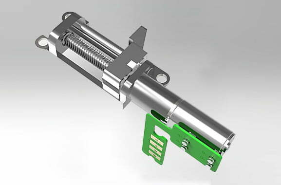
Step angle varies by construction: hybrid steppers offer 1.8° or 0.9° per step, while cheaper permanent-magnet (PM) types are coarser (7.5° or 15°). Gearing is especially valuable for those coarse PM motors, because a 7.5° step through a 10:1 gearbox becomes 0.75° — fine enough for many instrument and valve applications without upgrading to a more expensive hybrid motor.
Why a Stepper’s Torque Curve Makes Gearing Attractive
A stepper motor produces its maximum (holding) torque at zero speed, and that torque falls off sharply as speed rises. At 500–1,000 rpm a typical stepper may deliver only 30–40% of its holding torque, and it passes through a low-speed resonance band (roughly 100–300 rpm) where it can vibrate and lose steps. A gearbox solves both problems at once: it lets the motor spin in its high-torque, above-resonance range while the output shaft turns slowly with multiplied torque. See our page on micro stepper motors for the motor fundamentals.
How the Pairing Works
The stepper-and-gearbox combination changes four quantities in a predictable way. Here is each mechanism step by step.
1. Torque Multiplication
The gearbox multiplies motor torque by the ratio, minus friction losses. Output torque is Tout = Tmotor × i × η, where i is the ratio and η the gearbox efficiency. A 10:1 planetary at 90% efficiency turns 0.45 N·m of motor torque into about 4 N·m at the output.
2. Inertia Ratio Reduction
The load inertia “seen” by the motor shaft shrinks by the square of the ratio: Jreflected = Jload / i2. This is often the more important benefit. A load of 800 g·cm² through a 10:1 gearbox looks like only 8 g·cm² to the motor — a 100× improvement that dramatically sharpens acceleration and step control.
3. Step-Angle Refinement
Gearing divides the output step angle by the ratio: θout = θmotor / i. A 1.8° stepper through 10:1 delivers 0.18° per step — and combined with microstepping (e.g. 1/16) this reaches sub-0.01° resolution.
4. Resonance Avoidance
Because the output turns i times slower than the motor, the motor can be commanded to run faster and stay above its resonance band, reducing vibration, noise and the risk of missed steps.
Stepper + Gearbox Type Comparison
| Gearbox type | Efficiency | Backlash | Self-locking | Best for steppers |
|---|---|---|---|---|
| Planetary | 90–97% | Low (3–10 arcmin, ≤1 available) | No | Precision positioning, robots, CNC |
| Harmonic (strain-wave) | 70–90% | Very low (<1 arcmin) | No | High-precision, compact joints |
| Spur (parallel shaft) | ~90% | Medium | No | Cost-sensitive general motion |
| Worm | 50–70% | Higher | Yes | Self-locking lifts, valves |
For a stepper, the key trade-off is backlash vs. efficiency vs. cost. Because a stepper is usually open-loop, any gear backlash becomes uncorrected positioning error — so precision axes favor low-backlash planetary or harmonic stages. See harmonic drive vs. planetary gear for the detailed comparison.
Stepper + Gearbox vs Servo Motor
| Attribute | Geared stepper | Servo (often + gearbox) |
|---|---|---|
| Control | Open-loop (no feedback required) | Closed-loop with encoder |
| Cost | Lower for moderate precision | Higher (motor + drive + encoder) |
| Speed / dynamics | Good at low-to-medium speed | Excellent at high speed & fast reversals |
| Accuracy under load | Limited by backlash & stall risk | Corrected by feedback |
| Best for | 3D printers, instruments, pumps, simple axes | Robots, CNC, high-dynamic machines |
The choice is rarely “stepper or servo” in isolation — both often use a gearbox. A geared stepper wins on cost and simplicity where open-loop precision is enough; a servo wins where the axis must correct errors in real time. See the full servo vs stepper breakdown.
Engineering Data: Torque, Inertia, Resolution
The following relationships govern how a geared stepper behaves. They are the same physics applied to any gearbox, but the numbers matter more here because a stepper has no feedback to correct errors.
Torque
Tout = Tmotor × i × η — output torque equals motor torque times ratio times efficiency. Holding torque at the output is what matters for static loads; dynamic torque is lower because the stepper’s torque falls with speed.
Reflected Inertia
Jreflected = Jload / i2. The inertia ratio is Jreflected / Jmotor rotor; keep it at or below about 10:1 (ideally ≤5:1) for stable, accurate stepping. Above that, the motor struggles to control the load and can stall or lose steps.
Step Resolution & Speed
θout = θmotor / i and nout = nmotor / i. Resolution improves and output speed drops by the same ratio, so a deeper ratio is not always better — it also lowers your achievable speed.
Efficiency by Stage
Planetary stages are ~90–97% efficient; each additional stage costs a few percent. Worm stages run 50–70% and generate heat at high ratio. Count the stages when you estimate real output torque.
Backlash: Why It Matters for Steppers
Backlash is angular play in the gear mesh, measured in arcminutes (1 arcmin = 1/60°). Because a stepper is open-loop, backlash converts directly into bidirectional positioning error the motor cannot correct. A gearbox with 30 arcmin of play on a 400 mm arm produces about 3.5 mm of drift at the end effector; a 5-arcmin planetary stage cuts that to under 0.6 mm. For repeatable bidirectional moves, specify ≤5 arcmin (and ≤1 arcmin for precision joints) — a constraint that rules out most worm and spur stages for exact positioning.
Worked Example: Inertia Matching a Rotary Stage
A designer must drive a rotary table with load inertia Jload = 800 g·cm² using a NEMA 17 stepper (holding torque 0.45 N·m, rotor inertia Jmotor = 40 g·cm², 1.8° step angle).
Without a gearbox (direct drive)
Inertia ratio = 800 / 40 = 20:1 — far above the ~10:1 ceiling. The motor would vibrate, struggle to accelerate the table and risk lost steps.
With a 10:1 planetary gearbox (η = 0.90)
| Quantity | Formula | Result |
|---|---|---|
| Reflected inertia | Jload / i2 | 800 / 100 = 8 g·cm² |
| Inertia ratio | Jreflected / Jmotor | 8 / 40 = 0.2:1 (excellent) |
| Output holding torque | Tmotor × i × η | 0.45 × 10 × 0.9 = 4.05 N·m |
| Output step angle | θmotor / i | 1.8° / 10 = 0.18° |
| Output speed (motor at 600 rpm) | nmotor / i | 60 rpm |
If even finer resolution is needed, the 0.18° step can be microstepped (1/16 → 0.011°), but remember microstepping refines smoothness, not guaranteed positional accuracy under load. For torque and inertia math on the motor side, see how to calculate motor torque.
Best Applications for a Geared Stepper
- 3D printers & CNC axes — fine resolution and moderate torque with low-cost open-loop control.
- Robotic joints & gantries — compact planetary/harmonic stages keep backlash low; see why robotic arms need speed reducers.
- Medical & lab instruments — infusion pumps, sample handlers, valve actuators where quiet, precise dosing matters.
- Security & building systems — PTZ cameras, smart locks, valve and damper actuators; a micro stepper with a micro gearbox fits tight envelopes.
- Peristaltic pumps & dispensers — high holding torque and controlled flow rate.
Typical Ratios by Application
| Application | Typical ratio | Dominant requirement |
|---|---|---|
| 3D printer extruder / Z-axis | 5:1–20:1 | Resolution + torque |
| CNC rotary table | 10:1–50:1 | Inertia match + resolution |
| Robotic joint | 50:1–100:1 | High torque, low backlash |
| Valve / damper actuator | 20:1–100:1 | Holding torque, sometimes self-locking |
| PTZ camera / instrument | 10:1–50:1 | Smoothness + compact size |
These ranges are starting points, not rules. The correct ratio always falls out of the three-step check in the selection guide above — torque, inertia and speed — not from a lookup table.
How to Select a Stepper Gearbox
- Compute the load torque (friction + gravity + acceleration, times a ≥1.5 safety factor) — this sets the minimum output torque.
- Set the inertia budget. Choose a ratio so
Jload/i2keeps the inertia ratio ≤10:1 (ideally ≤5:1). - Check speed. Confirm the reduced output speed still meets your cycle time; a deeper ratio lowers top speed.
- Pick the gearbox type. Planetary or harmonic for precision; worm only when self-locking is required. Compare types of speed reducers.
- Specify backlash. For open-loop steppers, demand low backlash (≤5 arcmin) so mechanical play does not become position error.
- Confirm the mechanical interface. Match flange, shaft and mounting to your integrated stepper or standalone motor.
Common Engineering Mistakes
- Ignoring the inertia ratio. Sizing only for torque and ending up with a 20:1 inertia mismatch that stalls the motor.
- Over-reducing. A very deep ratio kills output speed and adds stages (cost, backlash, efficiency loss).
- Using a worm gearbox for precision. Its ~60% efficiency and backlash undermine accuracy unless self-locking is the real requirement.
- Assuming microstepping = accuracy. Microstepping smooths motion but does not eliminate the mechanical error from gear backlash.
- Forgetting efficiency. Multiplying torque by the ratio alone (without η) overstates the true output torque.
- Ignoring the torque-speed curve. Using holding torque as if it were available at running speed leads to mid-cycle stall.
Troubleshooting — Problem, Cause, Solution
| Problem | Likely cause | Solution |
|---|---|---|
| Motor stalls mid-move | Inertia ratio too high, or torque understated | Increase ratio; verify output torque with efficiency; lower acceleration |
| Position drifts / poor repeatability | Gear backlash in an open loop | Switch to low-backlash planetary/harmonic; add closed-loop encoder |
| Vibration / missed steps at low speed | Running in the resonance band | Use gearbox to run motor faster; adjust microstep/damping |
| Gearbox runs hot | Worm stage at high ratio / low efficiency | Use planetary for continuous duty; check duty cycle and lubrication |
| Output too slow for cycle time | Ratio too deep | Reduce ratio; rebalance torque vs speed; use higher-speed motor |
| Backlash grows over time | Worn gear teeth / loose preload | Replace worn stage; confirm rated torque not exceeded |
FAQ
Why pair a stepper motor with a gearbox?
A gearbox multiplies torque by the ratio, reduces reflected load inertia by the square of the ratio, refines step resolution, and lets the motor run faster to escape its resonance band — so a smaller, cheaper stepper can drive a heavier, more precise load.
Does a gearbox increase or decrease stepper motor speed?
It decreases output speed by the ratio while increasing torque by roughly the same ratio minus efficiency losses. A 10:1 gearbox turns 600 rpm into 60 rpm with about 9× the torque at 90% efficiency.
What gear ratio should I choose for a stepper motor?
Size from three constraints: output torque, reflected inertia (keep load inertia / i² ≤ ~10× rotor inertia), and required resolution and output speed. Typical stepper ratios are 5:1 to 50:1.
Does a gearbox hurt stepper motor accuracy?
Backlash adds error an open-loop stepper cannot correct, so precision axes use low-backlash planetary or harmonic gearboxes (typically ≤5 arcmin) rather than worm or spur units with more play.
Can I use a worm gearbox with a stepper motor?
Yes, when self-locking is required (the load cannot back-drive the motor). But worm gearboxes are only ~50–70% efficient and have more backlash, so they are rarely the first choice for precision positioning.
Is a geared stepper motor better than a servo motor?
For moderate-precision, low-to-medium speed open-loop positioning, a geared stepper is cheaper and simpler. For high dynamics, closed-loop accuracy or continuous high-speed duty, a servo wins — see our servo vs stepper comparison.
Why Choose Greensky Power?
Greensky Power designs and manufactures custom electric motors and complete OEM actuator assemblies, so we treat the stepper and the gearbox as one matched system. For your program we supply:
- Stepper motors (hybrid, PM and micro) matched to low-backlash planetary, harmonic and worm gearboxes with documented torque, backlash and efficiency data.
- Integrated stepper motors and OEM hybrid stepper solutions with matched drivers for plug-and-play positioning.
- Engineering support for torque calculation, inertia matching and industrial motor selection.
Related Resources
- Gearbox overview (pillar page)
- Electric motor basics (pillar page)
- Stepper motor overview
- Micro stepper motor guide
- Precision planetary gearbox deep dive
- Planetary gear motor
- How a planetary gearbox works
- Planetary vs worm gear motor
- Servo vs stepper motor
- How to select a reduction gearbox for an electric motor
- Speed-reducer motor selection guide
- DC motors category
References
- IEC 60034-1:2022 — Rotating electrical machines, general requirements. webstore.iec.ch/en/publication/65446
- IEC 60034-30-1 — Efficiency classes of line-operated AC motors. webstore.iec.ch/publication/91195
- ANSI/NEMA MG 1-2021 — Motors and Generators. webstore.ansi.org/standards/nema/ansinemamg2021
- NEMA — Motor and generator product guidance. nema.org/products/pages/motor-and-generator.aspx
- U.S. DOE — Motor systems efficiency and load guidance. energy.gov — 10097517.pdf
- IEA — Electric motors and industrial efficiency. iea.org/energy-system/industry/electric-motors
- SKF — Bearing failures and their causes. skf.com — bearing failures
- Siemens — SIMOTICS electric motors product range. siemens.com — electric motors
- IEEE Xplore — Peer-reviewed motor / actuator design paper. ieeexplore.ieee.org/document/6342334
- IEEE Transactions on Industry Applications — Zhou & Shen, “Rotor Notching for Electromagnetic Noise Reduction of Induction Motors”, DOI 10.1109/TIA.2017.2681969. doi.org/10.1109/TIA.2017.2681969
- maxon — EC technology and gearhead selection. maxongroup.com — ec-technology
- FAULHABER — Brushless DC motors and micro-drive know-how. faulhaber.com — brushless DC motors
- Yaskawa — Motion and servo system technical downloads. yaskawa.com/downloads/search-index
- Tsubaki — Gearmotor selection technical reference (service-factor method). tsubakimoto.co.jp — selection reference
Technical content reviewed by the Greensky Power engineering team. Torque, inertia and resolution formulas follow standard motion-control practice; gearbox efficiency and backlash figures are representative ranges and vary by manufacturer and ratio.
