
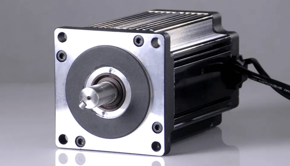
How to Set the Subdivision of Stepper Motor Driver : Full-Step to 1/256
[ez-toc]
What Is Stepper Driver Subdivision (Microstepping)?
A stepper motor normally moves in discrete full steps — typically 1.8° each, or 200 steps per revolution for a common hybrid motor. Subdivision is the Chinese literal translation of microstepping (细分 / 微步): the driver electrically splits each full step into N smaller increments by chopping the two-phase winding currents into sine and cosine levels. The rotor still follows the magnetic field vector; it does not become “infinitely positionable.” Microsteps are interpolation points between the motor’s physical full-step detent positions.
Why “Subdivision” Means Microstepping
English-speaking engineers search for “microstepping,” “microstep setting,” “set stepper driver microstep,” or “A4988/DRV8825 M0 M1 M2.” The existing page URL uses “subdivision,” which we keep for link equity while the body targets both terms. For the underlying motor physics, see our guide on what a DC motor is and how motor brushes differ from brushless commutation.
How Microstepping Works (Step-by-Step)
- Two windings, A and B. In full-step mode the driver energizes them in 4 discrete states, each 90° apart electrically (A+, B+, A−, B−).
- Microstepping quantizes the current vector. Instead of 4 states, the driver outputs I_A = I·sin θ and I_B = I·cos θ, where θ advances in 90°/N increments. The field vector rotates smoothly.
- Each increment is one microstep. The rotor chases the resultant field vector, moving a fraction of a full step.
- Mechanical step angle per microstep: α = (360° / steps_per_rev) / N = 1.8°/N for a 200-step motor (0.9°/N for a 400-step motor).
- Positions per revolution = 200·N. At 1/256 that is 51,200 positions/rev (ADI Trinamic microstepping).
- Constant-current vector. Because √(I_A² + I_B²) = I, the field magnitude stays roughly constant — that is what keeps a microstepping motor quiet compared with full-step chop.
Full-Step vs Half-Step vs Microstep: What Actually Changes?
| Mode | Microstep (N) | Step angle (1.8° motor) | Steps / rev | Holding torque per microstep (% of full-step) | Motion quality |
|---|---|---|---|---|---|
| Full step | 1 | 1.8° | 200 | 100% | Coarse, prone to resonance |
| Half step | 1/2 | 0.9° | 400 | ~70.7% (sin 45°) | Better, slight torque ripple |
| 1/4 | 1/4 | 0.45° | 800 | ~38.3% (sin 22.5°) | Smooth |
| 1/8 | 1/8 | 0.225° | 1,600 | ~19.5% (sin 11.25°) | Smoother |
| 1/16 | 1/16 | 0.1125° | 3,200 | ~9.8% (sin 5.625°) | Smooth, common default |
| 1/32 | 1/32 | 0.05625° | 6,400 | ~4.9% (sin 2.8125°) | Very smooth |
| 1/64 | 1/64 | 0.0281° | 12,800 | ~2.5% (sin 1.406°) | Very smooth |
| 1/128 | 1/128 | 0.0141° | 25,600 | ~1.2% (sin 0.703°) | Ultra-fine |
| 1/256 | 1/256 | 0.00703° | 51,200 | ~0.6% (sin 0.352°) | Ultra-fine, optical-grade |
The torque column is the key honest caveat: it comes directly from the incremental-torque relationship T_INC = T_HFS·sin(90°/N) documented in TI’s stepper selection app note (TI sloa293a). Notice that the motor’s full-step holding torque does not change — only the torque you can command between detents shrinks as you subdivide.
A4988 / DRV8825 M0/M1/M2 Pin Truth Table
| M0 | M1 | M2 | A4988 / DRV8825 microstep | Steps / rev (1.8° motor) |
|---|---|---|---|---|
| Low | Low | Low | Full step | 200 |
| High | Low | Low | 1/2 step | 400 |
| Low | High | Low | 1/4 step | 800 |
| High | High | Low | 1/8 step | 1,600 |
| Low | Low | High | 1/16 step | 3,200 |
| High | Low | High | 1/32 step | 6,400 |
| Low | High | High | 1/32 step | 6,400 |
| High | High | High | 1/32 step | 6,400 |
Note the A4988 tops out at 1/32 (M2 high forces 1/32 regardless of M0/M1). Newer TMC drivers reach 1/256 via software registers rather than pins. Never leave M0/M1/M2 floating — an undefined logic level puts the driver in an unpredictable mode.
Engineering Data: Step Angle, Torque, and Thermal Limits
| Parameter | Formula | Notes |
|---|---|---|
| Microstep step angle | α = 1.8° / N | 0.9°/N for a 400-step (0.9°) motor |
| Positions per revolution | P = 200 · N | 51,200 at N = 1/256 |
| Phase current (ideal) | I_A = I·sin θ, I_B = I·cos θ | Vector magnitude = I (constant) |
| Incremental holding torque | T_INC = T_HFS · sin(90°/N) | TI sloa293a / ADI Trinamic |
| Step pulse frequency | f_step = (rpm · steps_per_rev) / 60 | At 1/16 and 300 rpm → 16,000 steps/s |
Temperature and Insulation Limits (IEC 60034-1 / NEMA MG 1)
Microstepping does not materially change copper loss versus full-step at the same peak current, but two thermal facts matter. First, at standstill hold both windings carry rated current continuously, so the motor heats toward its insulation class — Class B = 130 °C, Class F = 155 °C, Class H = 180 °C per IEC 60034-1 and NEMA MG 1. Enable idle-current reduction (often 20–50% after a timeout) to stay inside those limits. Second, microstepping suppresses mid-band resonance, which is the usual cause of lost steps at speed — so it indirectly protects the coils from the over-current retries that follow a stall.
Efficiency Reality Check
Microstepping itself adds almost no copper loss; the driver’s chopping efficiency dominates. The real efficiency gain is avoided step loss — a resonant stepper that drops steps wastes the whole move. Where the gearbox is coupled (see our micro gear reducer problems guide), the lubrication film life follows AGMA 925 lambda-ratio rules independent of microstep count.
Best Applications for Microstepping
| Application | Recommended microstep | Why |
|---|---|---|
| CNC routers and mills | 1/8 – 1/16 | Smooth surface finish, low resonance |
| 3D printers and extruders | 1/16 | Quiet, precise filament path |
| Medical / diagnostic pumps | 1/32+ | Low vibration, accurate dosing |
| Camera gimbals, optics, scanners | 1/64 – 1/256 | Ultra-fine, near-silent positioning |
| Simple actuators, blinds, relays | Full or 1/2 | Cost and speed beat smoothness |
| High-torque start (conveyors) | Full / 1/4 | Need full detent torque, not interpolation |
The pattern is clear: pick microstepping for motion quality and low resonance, not for load torque. When you need to hold against a hard load, command a full-step detent position and let the driver deliver 100% holding torque.
Step-by-Step: How to Set Subdivision on Your Stepper Driver
- Identify the driver. A4988, DRV8825, TMC2xxx each have a different M0/M1/M2 (or software) mapping. Pull the datasheet truth table.
- Pick the smoothness-vs-torque point from the comparison table above (most motion lands at 1/8–1/16).
- Set the pins or DIP switch. For A4988, tie M2 high for the 1/32 ceiling; for 1/16 set M0=Low, M1=Low, M2=High.
- Set the current limit (VREF). Use the driver formula (A4988: VREF ≈ I_max · R_sense · 8) or the trim pot, matching the motor’s rated current and staying within IEC 60034-1 thermal class.
- Compute the step pulse rate. f_step = (rpm · steps_per_rev) / 60. At 1/16 (3,200 steps/rev) and 300 rpm you need 16,000 steps/s — confirm your controller can sustain it.
- Tune by ear and by move. Resonance at low speed → raise microsteps; torque loss at high speed → drop to 1/4–1/8 and raise current.
- Verify. Command exactly 200·N steps and confirm one clean revolution. If it over- or under-shoots, the pins are in the wrong mode.
Common Engineering Mistakes When Setting Subdivision
| Mistake | Why it bites | Fix |
|---|---|---|
| Assuming more microsteps = more accuracy | Accuracy is bounded by full-step detents and load; microsteps only interpolate | Size the motor for the real accuracy need |
| Setting 1/256 expecting to hold a load | Per-step torque is ~0.6% of full-step — easily overcome | Hold at a full-step detent for load bearing |
| Forgetting VREF after changing mode | Current stays the same but torque per microstep drops → stalls | Re-check current limit on every config change |
| Ignoring mid-band resonance | Motor loses steps in the 100–300 rpm band | Use 1/8–1/16 or anti-resonance drive (TMC SpreadCycle) |
| Floating M0/M1/M2 pins | Undefined logic level → random microstep mode | Tie every mode pin explicitly high or low |
| No idle-current reduction | Standstill hold overheats the windings | Enable 20–50% idle current in firmware |
Troubleshooting: Microstepping Problems
| Problem | Likely cause | Solution |
|---|---|---|
| Misses steps at speed | Microstep torque too low at high step rate / mid-band resonance | Drop to 1/4–1/8, raise current, enable anti-resonance |
| Audible whine / vibration at low speed | Current-vector quantization or mechanical resonance | Increase microsteps (1/16–1/32), tune decay / stealthChop |
| Overheats while idle | Full holding current flows at standstill | Enable automatic idle-current reduction |
| Inconsistent position between runs | Floating M pins / wrong mode | Tie M0/M1/M2 explicitly; verify with 200·N-step test |
| Jerky or uneven motion | Step pulse rate mismatched to speed | Recompute f_step and add an acceleration ramp |
| Weak torque under load | Commanding load between detents (low incremental torque) | Hold at full-step detent or reduce microstep count |
FAQ — Stepper Driver Subdivision
Does increasing microstepping increase positional accuracy?
No. Accuracy is bounded by the motor’s full-step detent positions and the mechanical load; microstepping only interpolates between them. It improves smoothness and reduces resonance, not absolute accuracy.
What is the holding torque at 1/16 microstep?
About 9.8% of full-step holding torque, because T_INC = T_HFS·sin(90°/16) = sin(5.625°) ≈ 0.098. The motor still has its full holding torque when commanded to a full-step detent; the microsteps in between carry less.
How do I set subdivision on an A4988 or DRV8825?
Set the M0/M1/M2 pins high or low per the driver’s truth table (for A4988: M0=M1=0, M2=1 → 1/16; M2=1 with any M0/M1 → 1/32). Industrial drivers use a DIP switch or a software register instead of pins.
Does microstepping reduce motor torque?
It reduces the torque available per microstep increment (the sin law above), but the motor’s full-step holding torque is unchanged. The main indirect torque cost is that at high microstep counts you cannot reach full torque between detents, and very high step rates cause mid-band drop.
Why does my stepper get hot when idle?
In full-step hold, both windings carry rated current continuously. Use the driver’s idle-current reduction (often 20–50% after a timeout) to cut standstill heating while staying within IEC 60034-1 insulation limits.
Can I just use 1/256 for everything?
Only if you need ultra-fine interpolation and do not require torque between detents. For most motion, 1/8–1/32 balances smoothness and usable torque; 1/256 mostly helps low-speed optical and scanning positioning.
Why Choose Greensky for Stepper and Motion Systems?
Greensky supplies hybrid stepper motors (1.8° and 0.9°, NEMA 8–34 frames), matching driver boards, and integrated stepper-plus-gearhead solutions with documented step angles, current ratings, and thermal classes per IEC 60034-1 and NEMA MG 1. Our OEM/ODM team helps integrators pick the right microstep count for their duty — whether that is a quiet 1/32 medical pump or a torque-dense full-step conveyor. Pair steppers with our robotic-arm speed reducers, worm-gear stages, or standard motor flanges, all at low MOQ for custom builds. See how we compare on brush vs brushless and brushed motor design, or troubleshoot drive-side issues in our DC motor troubleshooting guide, or see why a DC motor loses torque under load.
References
- IEC 60034-1 — Rotating electrical machines, Part 1: Rating and performance. webstore.iec.ch/publication/56979
- NEMA MG 1-2016 — Motors and Generators. nema.org/standards/view/mg-1-2016-motors-and-generators
- Analog Devices / Trinamic — Segmented Microstepping. analog.com/en/technical-articles/segmented-microstepping.html
- Texas Instruments — sloa293a: Methods for Validating and Selecting Stepper Motors. ti.com/lit/an/sloa293a/sloa293a.pdf
- IEEE Xplore — Stepper motor microstepping research. ieeexplore.ieee.org/document/9359603
- MDPI Energies (2021) — Stepper microstepping control study. mdpi.com/1996-1073/14/16/4914
- U.S. Department of Energy — Motor systems efficiency. energy.gov/eere/amo/advanced-manufacturing-office
- SKF — Bearing and motor maintenance. skf.com/us/products/bearings-units-housings
- maxon — Stepper motor application note. maxongroup.com/maxon/view/content/stepper-motors
- FAULHABER — Stepper motor technology. faulhaber.com/en/products/motors/stepper-motors
