
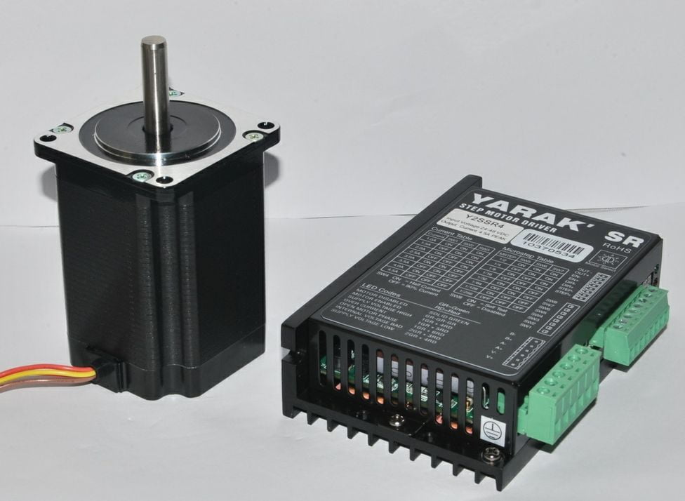
Subdivision vs Non-Subdivision of Stepper Motor Drive: What Actually Changes
Quick Answer: Subdivision (microstepping) drives the stepper with sine/cosine phase currents, splitting each 1.8° full step into up to 256 smaller microsteps for smoother, quieter motion. Non-subdivision (full-step) simply switches two coils fully on/off, holding 100% rated torque but moving in coarse 1.8° jumps. Microstepping improves smoothness and commanded resolution — not true mechanical accuracy — and its holding torque at a micro-position drops to as little as 0.61% of rated at 1/256 (per ADI Trinamic). Choose full-step for maximum torque and lowest driver cost; choose subdivision when vibration, noise, or mid-band resonance would otherwise fail the application.
[ez-toc]
What Is Subdivision (Microstepping) and Non-Subdivision (Full-Step)?
A hybrid stepper motor’s physical step angle is fixed by its rotor/tooth count — a standard 1.8° unit makes 200 full steps per revolution. How the driver energizes the two windings decides what the user experiences. There are two families:
Non-subdivision (full-step drive)
In full-step mode the driver applies only two discrete current states per phase: 100% or 0%. The most common variant, dual-phase full-step (high-torque mode), energizes both windings simultaneously, so the rotor always sits on a natural detent where the magnetic vector is strongest. The motor delivers its full rated holding torque but “snaps” between 1.8° positions, causing vibration and mid-band resonance at certain speeds.
Subdivision (microstepping)
Subdivision — universally called microstepping in US technical literature — replaces the on/off switching with a precisely proportioned sine/cosine current in the two phases. Dividing one full step into N microsteps lets the rotor rest at stable positions between natural steps. Common ratios are 1/4, 1/8, 1/16, 1/32, and up to 1/256. A 1.8° motor at 1/256 yields 51,200 discrete positions per revolution (0.00703125° per microstep) — an ADI Trinamic figure we will use later as a quantitative anchor.
Half-step: the bridge between them
Half-step alternates one-phase-on and two-phase-on excitation, doubling resolution to 400 steps/rev (0.9°) while introducing a ~30% torque ripple between the two states. It is technically a 2× subdivision and is best treated as the low-end entry point to microstepping.
How Subdivision vs Non-Subdivision Works — Step by Step
1. Current command in full-step
The driver holds Phase A at +IMAX and Phase B at 0, then flips to A=0, B=+IMAX, etc. There is no intermediate current; the resultant torque vector jumps 90 electrical degrees per step. Energy stored in the winding inductance causes the rotor to overshoot and ring like a damped pendulum — the source of full-step noise.
2. Current command in microstepping
The driver modulates both phases with a sinusoidal reference:
| Phase | Current command | Effect |
|---|---|---|
| Phase A | IA = IMAX · sin(θ) | Rotating magnetic vector |
| Phase B | IB = IMAX · cos(θ) | 90° shifted, smooth transition |
| θ step | θ = 360° / (200 · N) | N = microstep ratio (e.g. 16, 256) |
Because the torque vector rotates gradually instead of jumping, overshoot amplitude shrinks with microstep resolution — and so does vibration and audible noise. The quality of the sine wave itself is bounded by the driver’s ADC/DAC resolution; ADI Trinamic specifies ≥8-bit ADC/DAC, enabling up to 256 microsteps.
3. The critical distinction: resolution ≠ accuracy
This is the single most misunderstood point in the entire topic. Microstepping increases commanded resolution (smaller increments) but does not proportionally increase mechanical accuracy. The rotor settles at a magnetic-equilibrium position governed by load torque, friction, compliance, and current-regulation quality. As pmdcorp’s analysis shows, if a full step carries ±5% position error under load, that same error persists at 1/16 or 1/32 — the command is finer, the rotor is not proportionally more precise. IEEE TIE research confirms that further vibration optimization of the drive waveform is what actually reduces position error, not higher subdivision alone (Pillans, IEEE TIE 2021, DOI 10.1109/TIE.2020.2982123).
Side-by-Side Comparison: Full-Step, Half-Step, Microstepping
| Attribute | Full-Step (non-subdivided) | Half-Step | Microstepping (subdivided) |
|---|---|---|---|
| Steps / revolution (1.8° motor) | 200 | 400 | 3,200 (1/16) → 51,200 (1/256) |
| Step angle | 1.8° | 0.9° | ≤0.1125° (1/16) → 0.007° (1/256) |
| Holding / static torque | 100% rated | ~70–100% (ripples) | Up to 100% only at full/half positions |
| Smoothness | Poor, snaps | Moderate | Very smooth |
| Vibration / noise | High, resonant | Medium | Low |
| Mid-band resonance | Pronounced | Reduced | Greatly reduced |
| Driver complexity | Low (simple logic) | Medium | High (PWM sine, ≥8-bit DAC) |
| Cost | Lowest | Low | Higher (controller IC, sensing) |
| Best for | Max torque, cheap open-loop | Cheap smoother motion | Quiet, precise, resonance-free |
Engineering Data: Torque, Temperature, and Formulas
Incremental torque falls as subdivision rises
The most important quantitative fact competitors omit: at a microstep between full steps, neither phase carries full current, so the torque needed to displace the rotor from rest — the incremental torque (TINC) — shrinks. ADI Trinamic derives it from the step-ratio denominator (SDR):
| Microstep position (SDR) | TINC / THOLD | Interpretation |
|---|---|---|
| 1 (full step) | 100.00% | Maximum holding torque |
| 2 (half step) | 70.71% | Standard rest position |
| 4 | 38.27% | 1/4 microstep |
| 16 | 9.80% | 1/16 microstep |
| 32 | 4.91% | 1/32 microstep |
| 256 | 0.61% | 1/256 — almost no static hold at that point |
In practice this means: if a system must hold against a load while parked, stop the motor on a full- or half-step position. Microstepping’s torque penalty is largely invisible while the rotor is rotating, because the dynamic (rotational) torque is unaffected — the penalty shows only at rest.
Two equivalent torque formulas
TI’s application report sloa293a expresses the same idea with the single-step incremental torque:
| Formula | Meaning |
|---|---|
| TINC = THFS · sin(90° / N) | THFS = full-step holding torque, N = microstep ratio |
| IA = IMAX · sin(θ), IB = IMAX · cos(θ) | Phase current commands for smooth vector rotation |
| fSTEP = (RPM · Steps/rev) / 60 | Step (pulse) rate the controller must supply |
For a 1.8° motor at 1/16, Steps/rev = 3,200; at 600 RPM the driver needs fSTEP = (600 · 3,200) / 60 = 32,000 pulses/s. Higher subdivision multiplies the pulse-rate requirement, which is why controllers and EMI budgeting matter more at fine microsteps.
Temperature and rating context (IEC / NEMA)
Drive mode does not change the motor’s insulation class, but subdivision changes how hard the windings work. In full-step the current is clamped to IMAX; in microstepping the RMS current is similar, yet smoother transitions reduce copper-loss spikes. Still, the motor itself must meet IEC 60034-1 temperature classes (B 130 °C / F 155 °C / H 180 °C) and NEMA MG 1 rating rules — Greensky specifies these on every stepper datasheet, just as we do for our three-phase asynchronous motors. Resistance rises ~0.4% per °C, so a hot motor loses both torque and microstep fidelity.
Efficiency note
Open-loop steppers (both modes) draw near-constant current regardless of load — efficiency is modest (typically 40–60% in motion, near zero at stall). Subdivision does not materially improve electrical efficiency; its energy benefit comes from reducing mechanical vibration losses and allowing lighter mechanical structures. For perspective on higher-efficiency alternatives, see our ultra-efficient asynchronous motor guide.
Best Applications for Each Drive Mode
| Application | Recommended mode | Why |
|---|---|---|
| Low-cost dispensers, relays, simple actuators | Full-step | Max torque, cheapest driver, noise irrelevant |
| 3D printers, plotters (budget) | 1/8–1/16 | Smooth layers, acceptable accuracy |
| Medical pumps, lab scanners | 1/16–1/32 | Quiet, low-vibration, steady low-speed |
| Camera gimbals, optical alignment | 1/32–1/256 | Ultra-fine, resonance-free; accuracy still needs mechanics |
| CNC (when servo too costly) | 1/8–1/16 + closed-loop | Smooth + step-out protection |
| Valves, PTZ cameras (hold position) | Park on full/half step | Avoid microstep holding-torque loss |
Note the cross-link to our micro gear-reducer troubleshooting guide: a stepper + gearhead pairing shifts the accuracy burden from microsteps to the gearbox’s mechanical ratio.
Step-by-Step Selection Process
1. Define the accuracy requirement in arc-minutes, not “microsteps”
Convert the needed precision to a mechanical angle. If you need ±0.1°, a 1.8° motor at 1/16 (0.1125°) is borderline; pair it with a 5:1 gearhead instead of chasing 1/256.
2. Check the holding-torque margin at rest
If the load must be held statically, ensure the rest position is full/half-step and that THOLD exceeds load by ≥2×. Do not rely on a 1/256 micro-position to hold torque.
3. Match subdivision to speed
Below ~1,000 RPM, subdivision smoothness pays off. Above it, winding inductance flattens the sine wave and benefits diminish — full or half-step with good current control often performs as well.
4. Budget the pulse rate and EMI
Compute fSTEP. If it exceeds your controller’s reliable output or stresses EMI limits, drop to 1/8–1/16.
5. Decide closed-loop only if step-out risk is real
For variable or shock loads, add an encoder (see our inverter-motor failure piece on feedback and protection). Microstepping alone cannot detect or correct step-out.
Common Engineering Mistakes
| Mistake | Why it fails | Fix |
|---|---|---|
| Assuming more microsteps = more accuracy | Resolution ≠ mechanical accuracy; friction/compliance dominate | Specify gear ratio + mechanics, not just N |
| Over-subdividing (1/256) for a coarse system | Incremental torque →0.61%; friction masks microsteps | Use 1/8–1/32 unless optics demand more |
| Parking a holding load on a micro-step | Holding torque collapses at micro-positions | Command a full/half-step rest position |
| Ignoring current-regulation quality | Distorted sine → ripple, lost smoothness | Use ≥8-bit DAC driver (e.g. Trinamic-class) |
| Expecting microstepping to add torque | It redistributes, not increases, torque | Size the motor for full-step torque |
Troubleshooting: Subdivision-Related Problems
| Problem | Cause | Solution |
|---|---|---|
| Loud buzzing at standstill | Full-step resonance / poor current chopping | Switch to 1/8–1/16; enable stealthChop-class decay |
| Lost position under load | Micro-step holding torque too low vs load | Park on full/half-step; increase THOLD margin |
| Motor stalls at speed | Inductance flattens sine at high fSTEP | Reduce subdivision; raise supply voltage |
| Step-out, no error flag | Open-loop has no feedback | Add encoder / closed-loop; see DC torque-loss root-cause logic |
| Heats up in hold | Constant IMAX at rest | Enable auto-current-reduction (sleep/idle %) |
Frequently Asked Questions
Does microstepping increase a stepper motor’s torque?
No. Microstepping redistributes the torque vector across smaller angles; the rotational (dynamic) torque is essentially unchanged, and the static holding torque at a micro-position is actually lower. Size the motor using its full-step holding torque.
Does subdivision improve positioning accuracy?
It improves commanded resolution, not guaranteed mechanical accuracy. True position depends on load, friction, compliance, and current-regulation quality. Per IEEE TIE 2021, optimizing the drive waveform (not just raising N) is what reduces real position error.
What is the downside of 1/256 microstepping?
At 1/256 the incremental (holding) torque at that position drops to ~0.61% of rated, friction can exceed the microstep torque, and the controller must output 51,200 pulses per revolution. Benefits saturate well before that for most mechanical systems.
When should I use full-step instead of microstepping?
When you need maximum holding torque, the lowest driver cost, or operate in a noisy environment where smoothness is irrelevant (simple actuators, dispensers). Full-step also avoids the pulse-rate burden of high subdivision.
Can microstepping prevent step-out (lost steps)?
It reduces the tendency to resonate and stall, but open-loop microstepping cannot detect or correct step-out. For loads that vary or shock, add encoder feedback (closed-loop stepper).
How do I choose the right subdivision ratio?
Start at 1/8–1/16 for most motion; raise to 1/32–1/256 only for quiet optical/precision systems; and if you must hold a load statically, command a full- or half-step rest position regardless of ratio.
Why Choose Greensky for Stepper Drive Systems?
Greensky manufactures hybrid stepper motors (1.8° and 0.9°) from NEMA 8 to NEMA 34, matched subdivision drivers (1/8 to 1/256), and integrated stepper + gearhead units — all built to IEC 60034-1 and NEMA MG 1 ratings with documented holding-torque, step-angle, and temperature-class specs. Our engineering team helps you pick the right subdivision ratio versus a gear-reduction approach (we cover the brushed/brushless trade-off for power-tool-class drives too), documents the pulse-rate and EMI budget, and supports closed-loop upgrades when step-out risk is real. Low-MOQ ODM and full BOM traceability make Greensky a practical partner for automation OEMs. Explore our stepper driver subdivision setup guide or the DC motor troubleshooting hub for related drive topics.
References
- ADI Trinamic — Mastering Precision: Understanding Microstepping (incremental-torque table, 51,200 pos/rev). analog.com
- Texas Instruments — sloa293a, “Stepper Motor Microstepping with the DRV88xx” (T_INC = T_HFS·sin(90°/N)). ti.com
- pmdcorp — Microstepping Explained: When It Helps and When It Doesn’t (accuracy ≠ resolution). pmdcorp.com
- IEEE TIE 2021, Pillans — Reducing Position Errors by Vibration Optimization of Stepper Motor Drive Waveforms (DOI 10.1109/TIE.2020.2982123). ieeexplore.ieee.org
- ScienceDirect 2014 — Step-out detection and error compensation for a micro-stepper motor using current feedback. sciencedirect.com
- IEEE TIE 2015, Jung — Proximate In-Phase Current Estimator to Reduce Torque Ripple in PM Stepping Motors (DOI 10.1109/TIE.2015.2509949). ieeexplore.ieee.org
- IEEE Xplore 5530826 — Lyapunov-based control in microstepping with a nonlinear observer (>40% tracking improvement). ieeexplore.ieee.org
- maxon — Stepper motor application notes (product / drive selection). maxongroup.com
- IEC 60034-1 — Rotating electrical machines: ratings and temperature classes. iec.ch
- U.S. DOE — Motor systems efficiency guidance. energy.gov
