
Electric Motors for Solar Panel Cleaning Machines: Sizing the Drive
Quick Answer
An electric motor for a solar panel cleaning machine is sized by two loads, not by peak torque. Brush drag against the glass sets the running torque: a 1.2 m roller at 260 N and a friction coefficient of 0.4 needs about 6.2 N m and 196 W at 300 rpm. The duty cycle then cuts the continuous requirement to an RMS of about 2.7 N m. The environment adds two constraints no datasheet covers: at 60 °C ambient the frame loses about 9 percent of its torque, and on a wet 25 degree panel the machine may need a friction coefficient of 0.73 to climb while brushing.
- Three loads, and only one of them is torque
- Brush drag sets the running torque
- Torque cannot fix a traction problem
- The duty cycle, not the peak, sizes the motor
- A 60 °C ambient costs 9 percent of continuous torque
- IP65 is a jet rating, not a washdown rating
- How to read a coating claim
- Choosing the DC bus
- What to write on the specification sheet
- Six mistakes that reach the field
- Troubleshooting: symptom, cause, action
- How Greensky Power builds these drives
- References
- FAQ
Three Loads, and Only One of Them Is Torque
A photovoltaic cleaning machine has three loads that are usually discussed as one. The brush roller has to overcome friction against wet glass. The chassis has to hold station on a slope while the brush pushes against it. And the whole assembly has to survive water, dust and a surface temperature that can exceed the ambient by thirty degrees.
Only the first load is a torque problem. The second is a friction problem, and it is decided by normal force rather than by drive capability. The third is an enclosure and derating problem, and it is decided before the motor is chosen. A specification that addresses only the torque will produce a machine that cleans well on a test rig in a shed and fails on a roof in August.
| Load | What sets it | What the motor can do about it |
|---|---|---|
| Brush drag against glass | Brush pressure, friction coefficient, roller radius | Supplies the torque; this is the sizing case |
| Holding station on the slope | Machine mass, panel angle, friction, adhesion system | Nothing; more torque does not add grip |
| Enclosure and thermal duty | Water spray, dust, ambient, solar gain | Constrains the frame and the continuous rating |
Brush Drag Sets the Running Torque
The running torque comes from one multiplication: tangential force at the glass multiplied by roller radius. The tangential force is the friction coefficient times the normal force the brush exerts on the panel, and the normal force is set by how far the brush filaments are compressed against the surface.
Work a 1.2 m wide roller at 120 mm diameter. Assume 260 N of total brush normal force, which corresponds to a moderate interference on a medium-stiffness filament, and a friction coefficient of 0.4 for wet nylon against glass. The tangential force is 104 N, and at a radius of 0.06 m the roller torque is 6.24 N m.
| Quantity | Value | Where it comes from |
|---|---|---|
| Brush normal force, 1.2 m width | 260 N | Set by filament interference; measure it on the machine |
| Friction coefficient, wet brush on glass | 0.4 | The single number most worth measuring |
| Tangential force | 104 N | 0.4 × 260 |
| Roller radius | 0.06 m | 120 mm diameter |
| Roller torque | 6.24 N m | 104 × 0.06 |
| Power at 300 rpm | 196 W | 6.24 × 31.4 rad/s |
| Power per metre of width | 163 W/m | 196 ÷ 1.2 |
The coefficient of friction is the whole calculation in one number, and it changes with water film, dust loading and filament wear, so it should be measured rather than assumed. The other consequence is that torque is proportional to brush pressure, so a machine that presses harder to clean stubborn soiling also asks for more motor, more current and more grip.
Where the gearbox enters
At 300 rpm and 6.24 N m the roller needs 196 W, which is unremarkable. The reason these machines use a gearbox is not torque amplification but speed reduction: a brushless motor is efficient at 2,000 to 4,000 rpm while the roller usually wants between 200 and 600 rpm, so a reduction of roughly five to fifteen to one is required. Head traverse speed and brush stiffness decide where in that band the design sits.
Gearbox efficiency then decides how much of the motor’s output survives. A planetary stage at 90 percent means the motor must be sized for about 218 W rather than 196, and the same ratio applies to the torque rating. The options are set out in BLDC planetary gear motors and, for the general case, in industrial gearboxes.
Torque Cannot Fix a Traction Problem
This is the calculation that separates a machine that works from one that slides, and it contains no motor terms at all. Take a 45 kg machine on a panel inclined at 25 degrees.
| Quantity | Value | Derivation |
|---|---|---|
| Weight | 441.5 N | 45 kg × 9.81 |
| Down-slope component | 186.6 N | 441.5 × sin 25° |
| Normal force on the glass | 400.1 N | 441.5 × cos 25° |
| Friction coefficient just to hold station | 0.47 | tan 25° |
| Add brush drag while climbing | 290.6 N | 186.6 + 104 |
| Required friction coefficient | 0.73 | 290.6 ÷ 400.1 |
Wet rubber on glass delivers roughly 0.4 to 0.6. The requirement while climbing and brushing is 0.73. The machine slides, and doubling the motor changes nothing, because the available friction is fixed by the normal force and the normal force is fixed by weight.
Traction is a normal-force problem, not a drive problem. If the required friction coefficient exceeds what the wheel or track compound can deliver on wet glass, the only effective remedies are more normal force (a vacuum or suction system, or magnetic wheels on steel mounting rails), lower brush pressure, or a change of direction. Raising the motor rating increases the brush reaction and therefore makes the slide worse, not better.
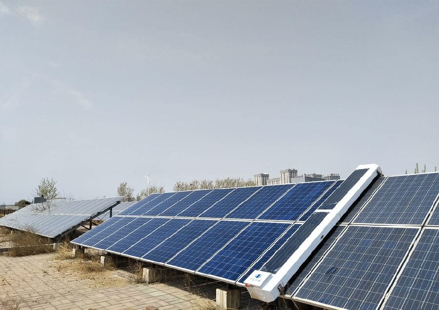
The direction of travel is a design variable
Run the same arithmetic downhill and the brush drag reverses sign: 186.6 minus 104 gives 82.6 N, and the required coefficient falls to 0.21. The machine that cannot climb while brushing can clean perfectly well on the way down.
Run the arithmetic downhill and the strategy reverses: climb with the brush lifted or at reduced pressure, then clean on the descent. The motor then only has to carry the brush load in the direction where gravity is helping, and the adhesion system only has to hold the machine on the way up. Machines that clean in both directions need either an adhesion system or a much lower brush pressure, and the specification should say which choice was made.
The Duty Cycle, Not the Peak, Sizes the Motor
A cleaning machine does not run continuously. It cleans a pass, repositions, stops, reverses and dwells, and the motor’s thermal duty is the root mean square of that cycle rather than its maximum. Take a 120 second cycle.
| Phase | Duration | Torque | Torque squared × time |
|---|---|---|---|
| Cleaning pass | 20 s | 6.5 N m | 845 |
| Reposition, brush lifted | 5 s | 1.5 N m | 11.3 |
| Stop and reverse | 5 s | 0 | 0 |
| Return traverse | 5 s | 1.2 N m | 7.2 |
| Dwell before next pass | 85 s | 0 | 0 |
| Cycle result | 120 s | peak 6.5 N m | RMS 2.68 N m |
The root mean square is 2.68 N m against a peak of 6.5, a ratio of 2.42. A motor chosen on the peak is therefore oversized by well over a factor of two, and on a machine that has to climb glass, that oversizing is paid for twice: once in cost and once in mass, which feeds straight back into the traction calculation above.
The peak still matters, but for a different reason. It sets the current the drive must deliver, the saturation margin in the gearbox, and the point at which the machine stalls if the brush jams. So the specification needs both numbers with their roles stated: continuous rating from the RMS, transient capability from the peak. The same reasoning applied to a battery-powered platform is worked through in motor efficiency and battery runtime.
A 60 °C Ambient Costs 9 Percent of Continuous Torque
Panel surfaces run hot. A black module in full sun can sit thirty degrees above ambient, and the air around a machine working on it is not much cooler. That matters because the continuous torque rating in a catalogue is normally stated for a 40 °C ambient, and the insulation class sets the ceiling.
Take a Class F winding, rated 155 °C total. At a 40 °C ambient the allowable temperature rise is 115 K. At 60 °C it is 95 K. Since temperature rise is proportional to losses, and copper loss is proportional to the square of torque, the allowable continuous torque scales with the square root of the rise ratio: the square root of 95 over 115 is 0.909.
| Ambient | Allowable rise, Class F | Relative continuous torque | Comment |
|---|---|---|---|
| 40 °C | 115 K | 1.00 | Normal catalogue basis |
| 50 °C | 105 K | 0.96 | Hot climate, ventilated housing |
| 60 °C | 95 K | 0.91 | The rating stated in the original version of this page |
| 70 °C | 85 K | 0.86 | Sealed housing in direct sun |
A sealed housing makes the derating worse
A motor with no cooling fan, which is what IP65 usually implies, has to shed the same losses through the frame surface alone, and the frame is a poor substitute for a forced airstream. A totally enclosed non-ventilated machine of a given frame therefore carries a much lower continuous rating than the fan-cooled version, and the two are routinely quoted from the same catalogue page.
So the honest specification is not “continuous torque at 40 °C” but “continuous torque at the stated ambient, with the stated cooling method”. Both halves are needed, because the derating arithmetic above assumes the motor still has whatever cooling the catalogue figure was taken with. Between the 60 °C derating and the loss of forced cooling, a drive specified from a catalogue page at 40 °C can end up with two thirds of its nominal continuous torque on a roof in summer.
IP65 Is a Jet Rating, Not a Washdown Rating
The first digit of an IP code covers solids and the second covers water, and the water digits are defined by specific tests rather than by adjectives. The definitions below come from IEC 60529, and the machine-side application is governed by IEC 60034-5 [1][2].
| Code | Test condition | What it does not cover |
|---|---|---|
| IPX4 | Splashing water from any direction | Directed jets |
| IPX5 | 6.3 mm nozzle, 12.5 L/min, 30 kPa, 3 minutes | Higher pressure, immersion, steam |
| IPX6 | 12.5 mm nozzle, 100 L/min, 100 kPa, 3 minutes | Immersion, steam cleaning |
| IPX7 | Immersion at 1 m for 30 minutes | Pressurised jets |
| IPX9K | High pressure, high temperature jet | Defined outside IEC 60529 |
IP65 is an entirely reasonable rating for a machine that sprays water onto glass some distance from its own motor. It is not a rating for a machine that gets washed down at the end of a shift, and it is certainly not a rating for one cleaned with a pressure washer. The failure is rarely through the housing wall; it is through a cable gland, a connector, a breather or a shaft seal, none of which the motor’s IP test covers once they are fitted by the machine builder.
An IP65 motor stays IP65 in service only through the parts the machine builder adds. The cable gland must be rated at least as high as the motor and must be tightened to its specified torque. Any breather or pressure-equalisation element must be a membrane type rather than an open hole. The shaft seal must also survive reversing duty, because a lip seal that runs in one direction for a season and then reverses can lift and admit a water film. If the end user washes the machine itself, specify IP66 or IP67 and state it on the drawing.
How to Read a Coating Claim
The original version of this page quoted three coating numbers: adhesion level 1, resistance to neutral salt spray, and 500 hours of humidity and heat. Each of those is a test result, and each becomes useful only when the test method and the acceptance criterion travel with the number.
Salt spray is a process check, not a lifetime forecast
ISO 9227 defines the neutral salt spray test among others, and its own scope statement is unusually direct: the methods are suitable for checking that the quality of a coated material is maintained, but they are not intended for comparative ranking of materials or for predicting long-term corrosion resistance [8]. A figure of 500 hours therefore says something about the coating process, not about how many years the machine will last on a coastal installation.
That does not make the test worthless. It makes it a control parameter, and a control parameter is only useful with its conditions attached: coating system and dry film thickness, test duration, whether the evaluation was for blistering, rusting or scribe creep, and the acceptance limit. A supplier who states the duration but not the criterion has given a number that cannot be compared with anyone else’s.
An adhesion class is not an adhesion measurement
ISO 2409 rates the resistance of a coating to separation using a lattice of cuts and a six-step scale, where class 0 is the best result and class 5 the worst. Class 1 means small flakes detached at the intersections, with up to 5 percent of the area affected. The standard also notes that the procedure is not a means of measuring adhesion, and points to a pull-off method where a measurement is required [9].
So a claim of adhesion level 1 is a claim that the coating reached the second-best band of a classification test. It is acceptable in most industrial specifications, but it is not the same as class 0, and it is not a measured adhesion strength. Stating the standard, the class and the substrate converts the claim into something a buyer can verify; stating “good adhesion” converts it into marketing.
Choosing the DC Bus
Most of these machines run from a battery, which makes the bus voltage the first electrical decision. Continuous shaft power of about 84 W at 300 rpm needs roughly 4.1 A on a 24 V bus and 2.1 A on 48 V, at an assumed 85 percent drive efficiency. The voltage choice is therefore less about current than about what the rest of the machine needs.
48 V halves the current for the same power, which reduces cable losses along a long traverse and lets a thinner cable survive the flexing at the cable chain. It also reduces the size of the drive’s power stage. Against that, 24 V is the more common battery configuration in small robots and has a wider choice of off-the-shelf chargers and DC-DC converters. Above 48 V the installation moves into a different safety regime in many markets, which is a systems decision rather than a motor one.
The connector, not the motor, is the detail to get right at either voltage. The motor is usually mounted on the brush head with a cable run that flexes every cycle, and a marginal connector is the most common cause of an intermittent drive fault that presents as a mechanical problem. Specify the connector, not just the motor. The general framework for this kind of selection is in how to select a motor for an industrial application.

What to Write on the Specification Sheet
A purchase order that says “IP65 gear motor, 200 W” leaves the supplier to choose the reduction ratio, the winding, the derating basis and the gearbox life, and those four choices determine whether the machine works.
| Line item | Why it matters |
|---|---|
| Continuous torque at the roller, after derating to 60 °C | The rating that actually governs brush duty |
| Peak torque and its duration | Jam recovery and start on a slope |
| Roller speed range and the corresponding motor speed | Fixes the reduction ratio and the brush tip speed |
| Duty cycle with phase durations | Lets the supplier verify the RMS rather than guess it |
| Enclosure rating with the standard referenced | Separates a jet rating from a washdown rating |
| Ambient and surface temperature range | Drives the derating and the insulation class |
| Gearbox life in reversing duty, in cycles | Reversing is the life-limiting case, not continuous running |
| Vibration grade to IEC 60034-14 | An unbalanced brush head destroys bearings before the motor wears out |
| Coating system with test method and acceptance class | Makes the durability claim checkable |
| Connector and cable specification | The most common field failure on a moving head |
Gearbox life in reversing duty is rarely quoted, because most catalogue life figures assume unidirectional running at constant load, which is the opposite of a cleaning machine’s cycle. The vibration grade also matters more than usual here, because the brush roller is an unbalanced load mounted on a shaft that reverses twice a minute; IEC 60034-14 gives the measurement and the limits [5].
Six Mistakes That Reach the Field
- Sizing on peak torque. The RMS is about 2.4 times lower on a typical cleaning cycle. The oversized motor adds mass, and mass is exactly what the traction calculation cannot afford.
- A slide is often read as a power problem. If the required friction coefficient on a wet slope exceeds what the wheel compound delivers, more torque makes the slide worse by increasing brush reaction.
- An IP65 motor rating is sometimes taken to mean the whole assembly is IP65. The gland, the connector and the shaft seal are outside the motor’s test, and they are where the water enters.
- Using the 40 °C continuous rating on a 60 °C roof. That is roughly a nine percent torque error before the loss of forced cooling is counted.
- Salt spray hours are sometimes quoted as a lifetime. ISO 9227 says its own methods are not intended to predict long-term corrosion resistance; the number is a process check and needs its acceptance criterion.
- Ignoring the reversing duty in the gearbox life. A planetary stage that lasts 20,000 hours unidirectional can fail far earlier when it reverses twice a minute with the brush load applied.
Troubleshooting: Symptom, Cause, Action
| Symptom | Most likely cause | Action |
|---|---|---|
| Machine slides on wet panels at high angle | Required friction coefficient exceeds the wheel compound | Lower brush pressure, add adhesion, or clean only downhill |
| Brush stalls but the motor draws normal current | Gearbox or coupling slip, not a drive fault | Inspect the output stage; check for a sheared key or a slipping clutch |
| Drive trips after twenty minutes in sun | Thermal derating not applied for a 60 °C ambient | Log winding temperature; re-rate the motor or improve the housing |
| Water found inside the terminal box | Gland torque, cable direction or a missing membrane breather | Re-terminate with a rated gland; route the cable in a drip loop |
| Intermittent drive fault on the moving head | Connector wear in the flexing cable run | Replace with a rated cyclic-duty connector; add strain relief |
| Coating blisters within one season | Surface preparation, not the coating system | Check the pretreatment and the dry film thickness, not the salt spray hours |
| Vibration and bearing noise after a few months | Brush roller imbalance, or a bent output shaft from a jam | Rebalance the roller; check shaft runout against IEC 60034-14 |
How Greensky Power Builds These Drives
We build the motor and the reduction as one unit, because the number the machine builder needs is the torque at the brush roller and not the torque at the motor shaft. A quotation from us states the continuous torque after derating to the ambient the customer names, the peak torque with its permitted duration, and the gearbox life in reversing cycles rather than in hours of unidirectional running.
Before we quote we ask for three inputs, because each changes the answer more than the power rating does: the brush normal force and the measured friction coefficient, the panel angle range, and the phase durations of the cleaning cycle. With those three in hand, the traction check and the RMS check are arithmetic rather than opinion, and we will say so in writing if the machine as drawn cannot hold station on the steepest panel in its range.
If you are at the stage where the brush and the panel angle are still being chosen, send those first. They constrain the drive more than the wattage does. Send the duty cycle to our engineering team, or start from the motor application library and the custom motor programme. Adjacent cleaning applications follow the same logic: pool cleaning machines, and for the tracking side of a photovoltaic plant, planetary gear motors for solar trackers.
The drive families behind these options are described in brushless DC motor technology, BLDC gear motors and 24 V DC brushless gear motors. Where the machine runs from a fixed supply instead of a battery, the comparison in BLDC versus induction motor is the relevant starting point, and the nameplate conventions that a replacement decision depends on are in how to read a motor nameplate.
Send us the brush normal force, the panel angle range and the cleaning cycle, and we will return the roller torque, the RMS continuous rating, the derated figure at your ambient and the gearbox life in reversing cycles, in writing. Contact Greensky Power.
References
- IEC. (2013). IEC 60529:1989+AMD1:1999+AMD2:2013 CSV, Degrees of protection provided by enclosures (IP Code), Edition 2.2. IEC Webstore. https://webstore.iec.ch/en/publication/2446
- IEC. (2020). IEC 60034-5:2020, Rotating electrical machines – Part 5: Degrees of protection provided by the integral design of rotating electrical machines (IP code) – Classification, Edition 5.0. IEC Webstore. https://webstore.iec.ch/en/publication/64224
- IEC. (2026). IEC 60034-1:2026, Rotating electrical machines – Part 1: Rating and performance, Edition 15.0. IEC Webstore. https://webstore.iec.ch/en/publication/89961
- IEC. (2025). IEC 60034-30-1:2025, Rotating electrical machines – Part 30-1: Efficiency classes of line operated AC motors (IE code), Edition 2.0. IEC Webstore. https://webstore.iec.ch/en/publication/91195
- IEC. (2018). IEC 60034-14:2018, Rotating electrical machines – Part 14: Mechanical vibration of certain machines with shaft heights 56 mm and higher – Measurement, evaluation and limits of vibration severity, Edition 4.0. IEC Webstore. https://webstore.iec.ch/en/publication/59889
- IEC. (2024). IEC 60034-2-1:2024, Rotating electrical machines – Part 2-1: Standard methods for determining losses and efficiency from tests, Edition 3.0. IEC Webstore. https://webstore.iec.ch/en/publication/67756
- IEC. (2021). IEC 61215-1:2021, Terrestrial photovoltaic (PV) modules – Design qualification and type approval – Part 1: Test requirements, Edition 2.0. IEC Webstore. https://webstore.iec.ch/en/publication/61345
- ISO. (2022). ISO 9227:2022, Corrosion tests in artificial atmospheres – Salt spray tests, Edition 5. ISO. https://www.iso.org/standard/81744.html
- ISO. (2020). ISO 2409:2020, Paints and varnishes – Cross-cut test, Edition 5. ISO. https://www.iso.org/standard/76041.html
- IEC. (2016). IEC TS 60034-30-2:2016, Rotating electrical machines – Part 30-2: Efficiency classes of variable speed AC motors (IE-code), Edition 1.0. IEC Webstore. https://webstore.iec.ch/en/publication/30830
FAQ
Q: What type of motor is used in a solar panel cleaning machine? Most machines use a brushless DC gear motor on a 24 V or 48 V bus, because the machine is battery or panel powered and the brush roller needs a large reduction ratio at low speed. Corded industrial units use an induction gear motor with a VFD. The deciding requirement is not the motor family but the enclosure rating, the continuous torque after derating for a 60 °C ambient, and whether the gearbox can survive reversing duty.
Q: How much torque does a solar panel cleaning brush need? It follows from the brush normal force and the friction coefficient: torque is friction force times roller radius. A 1.2 m roller pressed at 260 N with a friction coefficient of 0.4 on wet glass needs about 104 N of tangential force, which is about 6.2 N m at a 120 mm diameter. That is roughly 196 W at 300 rpm, or 163 W per metre of brush width.
Q: Why does a cleaning robot slide on wet panels? Because the available friction is fixed by the normal force, which comes from weight and any adhesion system. On a 25 degree panel a 45 kg machine needs a friction coefficient of 0.47 just to hold station, and once the brush drag is added it needs about 0.73, which is above what wet rubber achieves on glass. More motor torque does not help; only normal force, lower brush pressure or cleaning downhill does.
Q: Is IP65 enough for a solar panel cleaning machine? IP65 is a dust-tight enclosure tested against water jets from a 6.3 mm nozzle at 12.5 litres per minute and 30 kPa for three minutes. It is not a washdown or immersion rating. If the customer cleans the machine itself with a pressure washer, the requirement moves to IP66, IP67 or IP69K, and the weak point is usually the cable gland or connector rather than the motor body.
Q: How should I size the motor for an intermittent cleaning cycle? Use the root mean square torque over the whole cycle, not the peak. A 120 second cycle that spends 20 seconds at 6.5 N m and the rest near zero gives an RMS of about 2.7 N m, so a 6.5 N m peak duty needs a motor with roughly 2.7 N m continuous rating. Sizing on the peak oversizes the motor by about 2.4 times and adds unnecessary mass to a machine that has to climb glass.
Q: Do coating claims such as 500 hours salt spray prove durability? No. ISO 9227 states explicitly that salt spray tests are not intended for comparative ranking of materials or for predicting long-term corrosion resistance. They detect discontinuities such as pores in a coating. A salt spray figure is useful as a process control number, provided the coating system, the test duration and the evaluation criterion are all stated, and provided the adhesion test that accompanies it names its own standard and class.