
From Throttle Signal to Phase Current: What an Ebike Controller Does
Quick Answer
An ebike controller combines a three-phase inverter with a microcontroller. The sensors report throttle position, pedal rotation and rotor position. The microcontroller uses those inputs to set the duty cycle of six switches, which convert the battery supply into three phase waveforms. Current feedback lets the controller regulate motor torque; the remaining circuits handle filtering, switching and protection.
- The Short Answer: An Inverter With a Brain
- Follow One Throttle Signal Through the Box
- Inside the Bridge: Six Switches, Three Phases
- Commutation: Six Steps or a Sine Wave
- PWM, Duty Cycle and the Phase-Current Surprise
- The Three Loops: Current, Speed and Assist
- How the Controller Decides How Much Help to Give
- Torque Sensing, and Why It Beats Cadence
- Six Protections and What They Actually Protect
- Matching Controller, Motor and Battery
- How Controllers Die
- Why Greensky Power
- References
- FAQ
The Short Answer: An Inverter With a Brain
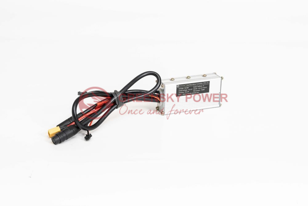
Inside the display, connectors and potting are a power stage and a microcontroller. The controller sets how much battery voltage to apply, while the power stage switches that voltage across the three windings in sequence.
The motor makes control more demanding than a simple resistive load. Current lags voltage, back-EMF rises with speed, and inductance resists rapid changes. The controller must account for all three to produce torque without overstressing its switches.
| Block | What it does | What it is protecting itself from |
|---|---|---|
| Input filter | smooths the battery current and suppresses switching noise | capacitor ripple current and voltage spikes |
| Six-switch bridge | connects each phase to positive or negative | shoot-through and overcurrent |
| Gate driver | turns the switches on and off fast enough | slow switching, which becomes heat |
| Current shunts | measure battery and often phase current | current beyond the silicon rating |
| Microcontroller | commutation timing, duty cycle, protections | its own firmware assumptions |
| Sensor inputs | throttle, pedal sensor, Halls, brakes, speed | a broken sensor telling it nonsense |
The product family that packages these blocks for different voltage and power classes is on the ebike controller page; this article is about what happens inside.
Follow One Throttle Signal Through the Box
One way to see how the controller works is to follow a throttle signal through it. The rider turns the throttle, and the controller processes the signal through six stages before the motor responds. The timing and handling at each stage depend on the controller design.
| Stage | What happens | Typical value |
|---|---|---|
| 1 Sensor | Hall-effect throttle outputs 0.8 to 4.2 V | supply 5 V, ratiometric |
| 2 Sampling | ADC reads the signal and filters it | every 100 to 500 microseconds |
| 3 Demand mapping | voltage becomes a current or torque demand | 0 to rated current |
| 4 Current loop | compares demand with measured current | loop at 8 to 20 kHz |
| 5 PWM | duty cycle updated for the bridge | 16 to 25 kHz carrier |
| 6 Commutation | which pair of switches is active | changes six times per electrical revolution |
Riders can notice differences in the signal filtering and current loop. Heavy filtering can make the throttle feel less immediate, while a well-tuned current loop can make the response feel more direct. Throttle-to-current mapping also affects how the bike accelerates from a stop and may be subject to local rules.
Inside the Bridge: Six Switches, Three Phases
Six MOSFETs, two per phase, one high side and one low side. At any instant during normal commutation one high-side and one low-side device conduct, so current flows from the battery through two windings and back. The third phase is left floating until the next step.
FET count is easy to compare, but it does not establish a controller’s capability on its own. A six-FET and a twelve-FET model may both carry a 25 A rating. With an otherwise comparable design, the additional devices can share the load and reduce heating; actual performance also depends on the MOSFETs, cooling and construction.
Conduction loss can be estimated from the devices in the current path. If two MOSFETs each have an on-resistance of about 3 milliohms, a phase current of 20 A produces roughly 2 x 20² x 0.003 = 2.4 W of conduction loss, before switching losses. Because this loss rises with the square of current, doubling current can quadruple it. A controller’s current rating still depends on its full design, not the label alone.
The gate driver also affects losses. While a MOSFET switches, it briefly passes through a higher-resistance state and dissipates energy as heat. Faster switching can reduce that interval, but it can also increase electromagnetic interference, so driver design balances the two.
The same three-phase arrangement appears in every brushless application, from a hub motor to an industrial pump; the general topology is described in three-phase BLDC motor controllers.
Commutation: Six Steps or a Sine Wave
Commutation is the sequence used to energise the motor phases. It must track rotor position so the stator field produces torque; the ideal angle depends on the motor and control method.
| Method | How position is known | Current waveform | Character |
|---|---|---|---|
| Six-step, Hall | three Hall sensors, 120 electrical degrees apart | two phases on, one off | cheap, robust, audible torque ripple |
| Sine, Hall | same sensors, interpolated | three phases modulated continuously | quieter, smoother, slightly more computation |
| Field-oriented | encoder or observer | current split into torque and flux components | best low-speed behaviour and efficiency |
| Sensorless | back-EMF zero crossings | six-step or observer-based sine | no Hall cable, but no signal at standstill |
Hall sensor spacing can affect compatibility. Many hub motors use 120 electrical degrees, while some use 60; these arrangements may not work with the same controller settings. A mismatch can cause stuttering, reverse rotation or a failed start, symptoms that can be mistaken for a motor fault.
Sensorless control has a limitation at low speed: back-EMF rises with speed, leaving little or no signal to measure at standstill. Starting a loaded direct-drive hub can therefore be difficult for some sensorless controllers. Hall sensors provide rotor-position information from startup. The waveform choices and their trade-offs are compared in the sine wave controller series.
PWM, Duty Cycle and the Phase-Current Surprise
The bridge does not produce a variable voltage. It switches between zero and the full battery voltage thousands of times a second, and the motor’s inductance averages the result. The fraction of time spent connected is the duty cycle, and duty multiplied by battery voltage is the average voltage the winding sees.
The buck-converter analogy
The motor inductance smooths the switched voltage, but current and voltage do not scale in the same way. In an ideal buck-converter model, output current is approximately input current divided by duty cycle:
I_phase is approximately I_battery / D
At 20 percent duty, an idealized example gives about 50 A in the winding for 10 A drawn from the battery. The actual current depends on the controller’s switching strategy, losses and operating conditions. The relationship reflects the trade between voltage and current.
This relationship helps explain why battery-current ratings alone do not describe low-speed loading. During a hill start, phase current can exceed battery current substantially; the actual value depends on the controller and operating conditions. As duty approaches 100 percent, the difference between battery current and phase current narrows.
When a controller is rated at 25 A, check whether the figure refers to battery current or phase current. At low speed, the two can differ considerably, and both ratings matter when assessing a hill start.
The Three Loops: Current, Speed and Assist
Controllers often use nested control loops. Knowing which loop sets a limit can help explain why a tuning change does not produce the expected response.
- Current loop, fastest. Compares measured phase current with demand and adjusts duty. This is the loop that keeps torque predictable and protects the silicon. Typical bandwidth is a few kilohertz.
- Speed loop, slower. Compares wheel speed with the target and sets the current demand. Cruise control and speed-limited modes live here.
- Assist loop, slowest. Decides how much current the rider’s effort should be multiplied by. This is where cadence sensing, torque sensing and the assist level setting meet.
The outer loops set demands that remain subject to the inner current limit. If assist requests 40 A while the current loop is capped at 15 A, the controller limits output to 15 A. The result may feel like weak assist even though the system is operating as configured.
The way those demands are produced from the motor side, including how torque and current relate, is covered in the BLDC controller guide. How sensors and controller share the work on a bicycle specifically is set out in sensors and controller for an ebike.
How the Controller Decides How Much Help to Give
On a typical pedelec, assist demand may come from the throttle and a cadence sensor at the crank. Their interaction accounts for some rider complaints about how assist responds.
The cadence sensor is a ring of magnets and a Hall element at the bottom bracket. Each rotation produces a fixed number of pulses, and the controller converts pulse rate into crank speed. Assist is then proportional to that speed, which is why the motor helps more when the rider pedals faster.
When both inputs are available, some controllers use the higher of the two current demands rather than averaging them. This lets the rider pedal gently while using the throttle for a short increase in power. The exact behavior depends on the controller firmware.
The start-up gap, and why it exists
With cadence sensing, the controller must receive a pulse before it can detect pedalling. This can delay assist at startup, including on a hill. Some firmware adds low-speed assist to reduce the delay; depending on its settings, that may make the bike surge when the cranks begin to turn.
A torque sensor measures pedal force using a strain gauge or magnetostrictive element. That lets the controller respond to effort rather than waiting for cadence pulses, although response time and proportionality depend on the sensor and firmware. The options and their trade-offs are set out in what a torque sensor on an ebike does.
Torque Sensing, and Why It Beats Cadence
A cadence sensor measures crank speed; a torque sensor measures how much force the rider applies. They provide different inputs for calculating assist.
Cadence versus torque
| Property | Cadence sensor | Torque sensor |
|---|---|---|
| Measured quantity | pulses per second at the crank or wheel | crank or axle deflection |
| Response to a standing start | waits for the first pulse | immediate |
| Assist proportional to effort | no, proportional to pedal speed | yes, within the sensor range |
| Cost and complexity | low, a magnet ring and a Hall element | high, calibration and temperature compensation |
| Typical failure | magnet ring shifted, no assist at all | drift, causing assist to feel heavy or light |
A torque sensor’s signal chain helps explain its added complexity. A strain-gauge bridge produces a small differential signal that must be amplified, filtered and digitised. The controller may also compensate for temperature before using the reading. A Hall pickup on the motor shell can provide speed information, which may be combined with torque when calculating assist.
Sensor design affects how the controller interprets pedal input. The different sensor constructions and manufacturers are compared in the ebike torque sensor overview and torque sensors for a smooth ride. Examples of production bikes that use torque sensors are listed in which ebikes have torque sensors.
Six Protections and What They Actually Protect
Each protection responds to a particular electrical or thermal condition. Identifying which protection triggered can narrow down the cause of a cut-out.
| Protection | What it senses | What it is protecting | Typical threshold |
|---|---|---|---|
| Low voltage cut-off | pack voltage | the battery, not the controller | set per chemistry, see below |
| Battery overcurrent | input shunt | the cells and the input capacitors | controller rating, often 15 to 30 A |
| Phase overcurrent | phase shunts or desaturation | the MOSFETs | two to three times the battery rating |
| Over-temperature | NTC on the heatsink | the silicon junction | typically 75 to 85 degrees C case |
| Hall fault | invalid sensor combination | the motor from a false commutation | all-zero or all-one patterns |
| Throttle fault | signal outside 0.5 to 4.5 V | the rider, from a runaway start | open or shorted input |
What the low-voltage cut-off must be set to
Low-voltage cut-off depends on battery chemistry and configuration, which the controller may not detect automatically. As examples, the article gives about 31.5 V for a 36 V lead-acid pack (three 10.5 V blocks), about 30 V for a 36 V lithium pack with ten cells in series, and about 39 V for a 48 V pack with thirteen cells in series.
A lead-acid cut-off may let a lithium pack discharge too far, while a higher lithium threshold can reduce the usable range of a lead-acid pack. Either mismatch can be mistaken for a controller fault.

Matching Controller, Motor and Battery
Controller and motor selection starts with matching voltage, current, Hall angle and phase sequence. Other requirements depend on the application.
| Item | What must agree | What happens if it does not |
|---|---|---|
| Voltage class | 36, 48, 52 or 72 V nominal | cut-off misfires, or the bridge sees an overvoltage it was not rated for |
| Current rating | continuous battery current, plus a phase margin | thermal shutdown on climbs, or a short life |
| Hall angle | 120 or 60 electrical degrees | no start, stutter, or running backwards |
| Phase sequence | three wires in the correct order | the same symptoms as a wrong Hall angle |
Three numbers that must agree
Electrical frequency is calculated from motor speed and pole pairs, although datasheets do not always list it. A direct-drive hub with 46 poles (23 pole pairs) at 200 rpm has an electrical frequency of about 77 Hz. A geared hub at 1,000 motor rpm with five pole pairs is near 83 Hz. The controller’s current loop must be fast enough for the motor’s operating frequency.
That calculation is the same one used for any three-phase machine, and the underlying relation between poles and speed is set out in number of poles in a motor. For a cargo or mid-drive build, the torque and cadence trade-offs of the motor itself are covered in choosing a mid-drive ebike motor and in ebike motor types explained. The voltage side of the same decision, including why a 48 V system is the common compromise, is worked through in the 48 V controller selection guide.
How Controllers Die
Many controller failures fall into a few broad categories. The symptoms can suggest where to start, but measurements are needed to confirm the cause.
| Symptom | Most likely cause | What confirms it |
|---|---|---|
| Dead after a standing start on a hill | phase overcurrent, FET short | continuity between phase and battery negative |
| Runs, then cuts out after minutes | over-temperature or a sagging pack | case temperature and pack voltage under load |
| Motor stutters from rest | Hall fault or wrong Hall angle | sensor pattern while turning the wheel by hand |
| Throttle does nothing, lights on | throttle signal outside the valid window | voltage at the signal wire, 0.8 to 4.2 V |
| Works dry, fails wet | water at the cable entry | corrosion on the connector pins, not on the board |
| Assist cuts at 25 km/h | not a fault, a legal cut-off | firmware setting, if the market allows it |
Water ingress can occur at cable glands and connector seals, and temperature changes may contribute to condensation inside an enclosure. IEC 60529 defines ingress-protection ratings; the test conditions matter when assessing a controller mounted near a rear wheel.
Why Greensky Power
We build motors and can match them with controllers for projects that need a complete pair. Before release, the project team agrees on voltage class, continuous and peak phase current, Hall angle and electrical frequency at top speed.
An incompatible Hall angle can prevent the motor from starting, while current-loop settings affect the controller’s response. A mismatched battery cut-off can also shorten battery life. Checking these requirements during design can reduce troubleshooting later.
To discuss a motor and controller match, provide the battery voltage and chemistry, wheel size or gear ratio, rider and cargo mass, climb gradient and desired assist behavior. The engineering team can use these details to recommend a current rating, Hall arrangement and cut-off settings. Contact the engineering team.
References
- International Electrotechnical Commission. (2022). IEC 60034-1:2022 Rotating electrical machines – Part 1: Rating and performance. webstore.iec.ch/en/publication/65446
- International Electrotechnical Commission. (2014). IEC 60034-2-1:2014 Rotating electrical machines – Part 2-1: Standard methods for determining losses and efficiency from tests. webstore.iec.ch/en/publication/121
- International Electrotechnical Commission. (2018). IEC 60034-14:2018 Rotating electrical machines – Part 14: Mechanical vibration of certain machines with shaft heights 56 mm and higher. webstore.iec.ch/en/publication/59889
- International Electrotechnical Commission. (2013). IEC 60529:1989+AMD1:1999+AMD2:2013 Degrees of protection provided by enclosures (IP Code). webstore.iec.ch/en/publication/2452
- International Electrotechnical Commission. (2023). IEC 61800-9-2:2023 Adjustable speed electrical power drive systems – Ecodesign for power drive systems, motor starters, power electronics and their driven applications. webstore.iec.ch/en/publication/111276
- National Electrical Manufacturers Association. (2024). NEMA standards for motors and generators. nema.org/standards
- European Commission. (2019). Commission Regulation (EU) 2019/1781 laying down ecodesign requirements for electric motors and variable speed drives. eur-lex.europa.eu/eli/reg/2019/1781/oj
- European Parliament and Council. (2013). Regulation (EU) No 168/2013 on the approval and market surveillance of two- or three-wheel vehicles and quadricycles. eur-lex.europa.eu/eli/reg/168/2013/oj
- U.S. Consumer Product Safety Commission. (2024). 16 CFR Part 1512 – Requirements for bicycles. ecfr.gov/title-16/part-1512
- U.S. Department of Energy. (2024). Motors and drives systems – advanced manufacturing office resources. energy.gov/eere/amo/motor-systems
FAQ
Q: How does an electric bicycle controller work?
It converts a low-current demand signal into three switched phases. Sensors report throttle position, pedal movement and rotor position; the microcontroller turns that into a duty cycle for a six-switch bridge, which chops the battery voltage into three sine or six-step waveforms. Current sensing closes the loop so the motor gets a defined torque rather than a defined voltage.
Q: Why is phase current higher than battery current?
Because the bridge behaves like a buck converter. At part duty the output current is the input current divided by the duty cycle, so 10 A from the battery at 20 percent duty corresponds to roughly 50 A in the phase winding. This is why a controller rated at 25 A can destroy a motor or itself when the bike is started on a steep hill.
Q: What is the difference between a sine wave and a square wave controller?
A square wave controller energises each phase in six discrete steps, which is simple and cheap but produces torque ripple and audible noise. A sine wave controller, usually running field-oriented control, modulates all three phases continuously so the current follows a smooth curve. The ride is quieter and smoother, and the same motor draws slightly less current for the same torque.
Q: What does the low voltage cut-off protect?
It protects the battery, not the controller. The threshold has to match the chemistry: about 31.5 V for a 36 V lead-acid pack, around 30 V for a 36 V lithium pack of ten cells in series, and about 39 V for a 48 V thirteen-cell pack. A cut-off set for lead-acid will over-discharge a lithium pack and shorten its life.
Q: Can I use any controller with any hub motor?
No. Three things have to agree: the voltage class, the current rating and the Hall sensor angle. A 120 degree motor on a 60 degree controller will not run cleanly, and a sensorless controller may refuse to start a loaded direct-drive hub. Phase wire colours are not a standard either, so the sequence has to be confirmed before the throttle is used.
Q: Why do controllers fail in wet weather?
Water reaches the electronics through the cable entry, not through the housing. The gland, the grommet and the connector seals are the weak points, and a controller that is only splash rated will collect condensation inside a sealed box as it heats and cools. Ingress protection is defined by IEC 60529, and a rating without the test condition says very little.