

Concrete Vibrator Motor: Three Architectures, One Force Equation
Quick Answer
A concrete vibrator motor is the drive that spins an eccentric mass so fresh concrete stops behaving like a solid and releases its entrapped air. The market splits three ways: a flexible-shaft poker driven by a 1 to 3 kW induction motor on the ground, a motor-in-head poker running at 42 V, three-phase, 200 Hz for 12,000 vibrations per minute, and an external form vibrator on a 2-pole motor at 3,000 or 3,600 rpm producing 0.4 to 100 kN of centrifugal force. Selection is decided by frequency, amplitude and centrifugal force, not by watts. A 100 W phone motor and a 100 W poker share a number and nothing else.
- What a concrete vibrator motor actually drives
- Frequency, amplitude and the square law
- The three architectures side by side
- Head diameter sets frequency, amplitude and spacing
- What the rating plate does not say
- A worked example: the same frame on 50 Hz and 60 Hz
- From radius of action to cubic metres per hour
- Which motor technology fits which machine
- The operating rules the motor depends on
- Seven mistakes that reach the mix
- Troubleshooting: symptom, cause, action
- Why Greensky Power builds the motor, not the poker
- References
- FAQ
What a Concrete Vibrator Motor Actually Drives
All a vibrator motor does is keep an unbalanced mass turning about an axis. The housing that holds the bearings reacts, the reaction travels into the concrete, and the mix liquefies for as long as the energy keeps arriving. Hose, head, bracket and handle are all packaging for that single rotating eccentric. Consolidation itself is the removal of entrapped air, not of water; a vibrator does not dewater a mix, and treating bleeding as a vibration problem is one of the oldest mistakes on site [1].
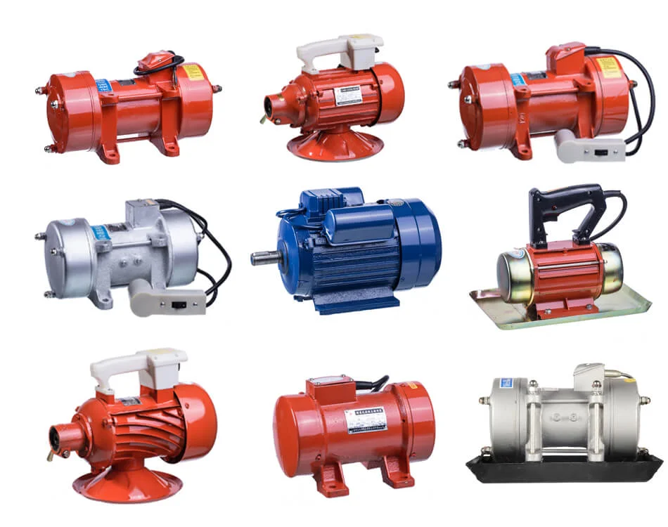
“Concrete vibrator motor” gets used for three different machines on the same pour, and they are not interchangeable. Each puts the motor in a different place, which changes the bearing load, the cooling path, the voltage and the failure mode. Splitting them apart first saves an argument later.
Flexible-shaft poker: the motor stays on the ground
A power unit carrying a 1 to 3 kW induction motor drives a flexible core inside a rubber hose. The core turns an eccentric inside the poker head, so the head oscillates while the motor sits on a frame or a tripod, well away from the concrete. The architecture separates heat from immersion: the motor cools in air, the head is small enough to enter congested reinforcement, and one power unit can serve heads of different diameters.
The cost is mechanical. A 3 to 6 m core running at high speed inside a curve loses energy to friction, and the hose is the part that fails first when it is bent too tight or run dry of grease. Every hour of shaft friction is an hour the head does not see.
Motor-in-head poker: the motor is the head
In a motor-in-head poker, the stator, rotor and eccentric share one sealed cylinder of 38 to 65 mm diameter, and the hose carries only stationary three-phase power. Nothing rotates between the operator and the head, so there is no rotating shaft seal to wear, and the head can be rated for continuous immersion. The trade-off is thermal: all the heat is generated inside a tube with no fan, and the concrete is the only heat sink.
That constraint sets both the voltage and the frequency. A 2-pole machine on a 200 Hz supply turns at 12,000 rpm, which is the frequency band concrete responds to, and 42 V keeps the operator-side risk low on a wet site.
External or form vibrator: the motor is bolted to the form
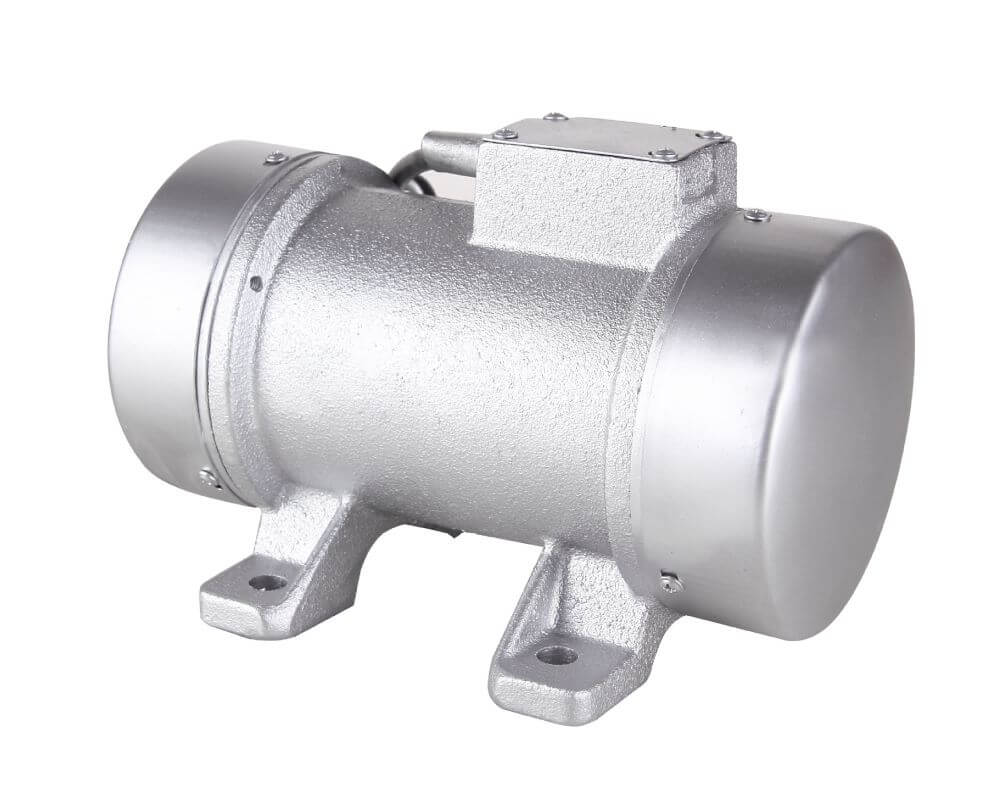
The vibrator is clamped or bolted to the outside of the formwork, and the form wall transmits the energy into the concrete. A 2-pole motor at 3,000 rpm on 50 Hz or 3,600 rpm on 60 Hz drives one or two eccentric weights on a through-shaft, with covers at each end. Force ranges from about 0.4 kN on a small single-phase unit to 100 kN on a cast-steel frame that weighs more than the operator [8].
Nothing enters the concrete, so formwork geometry is unrestricted. The weakness is on the other side of the wall: a flexible form absorbs the energy that was meant for the mix, and a vibrator that is powerful enough on a stiff steel form can be useless on a light aluminium one.
Frequency, Amplitude and the Square Law
Three numbers describe every vibrator, and they are easy to mix up. Frequency is how often the head oscillates, quoted in vibrations per minute or hertz. Amplitude is how far it travels from its rest position, quoted in millimetres, and the convention is not standardised. Centrifugal force is the peak force the eccentric generates, quoted in newtons or kilonewtons, and it is what moves stiff concrete.
Frequency follows directly from supply frequency and pole count, so the market clusters on a few speeds. For an induction machine the synchronous speed is n = 120 f / p, where f is the supply frequency in hertz and p the pole count. A 2-pole motor therefore gives 3,000 rpm at 50 Hz, 3,600 rpm at 60 Hz and 12,000 rpm at 200 Hz. That last figure is the reason high-frequency pokers are fed at 200 Hz, not at mains frequency.
Why force is bought with speed, not with mass
Centrifugal force is F = m · e · ω², where m is the mass of the eccentric in kg, e is its offset from the axis in metres, and ω is the angular velocity in rad/s, with ω = 2πn/60. The product m · e is the static moment, and it is the number a vibrator catalogue quotes. Doubling the eccentric mass doubles the force. Doubling the speed quadruples it. Speed is the cheap variable and the dangerous one, because the same square acts on the bearing load and on the form structure.
At 3,000 rpm, ω = 314 rad/s and ω² = 98,696 per second squared. A static moment of 0.05 kg·m therefore produces 4,935 N, or about 4.9 kN, and a 0.2 kg·m moment produces 19.7 kN. A supplier quoting a force figure should be able to show this arithmetic; recompute it when a quotation looks too good.
Amplitude is quoted three different ways
Amplitude is the least reliable number in a vibrator datasheet. Some catalogues give the half value, others the total, and some measure in air while others measure in concrete, where damping cuts the figure substantially. The two conventions differ by exactly a factor of two, which is enough to make two identical machines look 100 percent apart.
Settle which column you are reading before comparing brands. ACI 309R tabulates amplitude in air for internal vibrators, from 0.4 mm at a 20 to 40 mm head up to 2.0 mm at a 125 to 175 mm head, and that is the convention to normalise to [1].
The Three Architectures Side by Side
Most quotations leave this comparison out. Read it across a row, not down a column; what separates the architectures is the whole pattern of numbers, not any single value.
| Attribute | Flexible-shaft poker | Motor-in-head poker | External form vibrator |
|---|---|---|---|
| Where the motor sits | On a frame, 3 to 6 m from the head | Inside the 38 to 65 mm head | Bolted to the outside of the form |
| Typical motor | 2-pole three-phase induction, 1 to 3 kW | 2-pole induction, 42 V three-phase, 200 Hz | 2-pole induction, 1-phase 230 V or 3-phase 230/400 V |
| Nominal frequency | 9,000 to 12,000 vpm through the shaft | 12,000 vpm (200 Hz) or 9,000 vpm (150 Hz) | 3,000 vpm at 50 Hz, 3,600 vpm at 60 Hz |
| Centrifugal force | Set by head; typically 1.7 to 7.3 kN | 1.7 kN at 38 mm head to 7.3 kN at 65 mm | 0.4 kN to 100 kN across the frame range |
| Rated power | 1 to 3 kW at the power unit | 0.5 to 1.3 kW inside the head | 0.04 to 10 kW |
| Duty | S1 on the motor, hose-limited in practice | S1 continuous, thermal switch in the stator | S1 on good frames, S2 or S3 on cheap ones |
| Wet-end protection | Head sealed, hose exposed | Head IP68, switch box IP66, plug IP44 | Housing IP65 or IP66 |
| Fits congested steel | Yes, with a small head | Yes, best ratio of head size to force | No, access is outside the form |
| First thing to fail | Core wear and hose heat | Bearing and seal at the head | Winding, on an undersized duty class |
Watch the power and duty rows. The power row is not comparable across columns: motor-in-head designs deliver 1.7 to 7.3 kN from 0.5 to 1.3 kW, while external frames deliver 0.4 to 100 kN from 0.04 to 10 kW. Normalising both to kilonewtons per kilowatt gives roughly 3 to 6 kN/kW for a poker head and roughly 9 to 12 kN/kW for a form vibrator, a factor of two to three. Anyone comparing them on that ratio is comparing the wrong machines.
The duty row is where money is saved and lost. A 5 kN frame sold with 0.55 kW and the same 5 kN frame sold with 0.34 kW are not the same product. The lower-power version is a derated or short-time design, and it will behave accordingly on a form that is vibrated for eight hours [4].
Head Diameter Sets Frequency, Amplitude and Spacing
Head diameter is the master variable for internal vibrators, because it fixes the frequency the head can sustain, the amplitude it can develop, the radius of concrete it can consolidate and the rate at which the crew can place. ACI 309R tabulates the practical bands, and the pattern is consistent: as the head grows, frequency falls and amplitude rises.
| Head diameter | Frequency in concrete | Amplitude in air | Radius of action | Placement rate | Typical use |
|---|---|---|---|---|---|
| 20 to 40 mm | 150 to 250 Hz | 0.4 to 0.8 mm | 75 to 150 mm | 1 to 4 m³/h | Thin members, confined spaces, congested steel |
| 30 to 65 mm | 140 to 210 Hz | 0.5 to 1.0 mm | 125 to 250 mm | 2 to 8 m³/h | Walls, columns, beams, precast piles |
| 50 to 90 mm | 130 to 200 Hz | 0.6 to 1.3 mm | 175 to 350 mm | 5 to 15 m³/h | General construction, slump below 75 mm |
| 75 to 150 mm | 120 to 180 Hz | 0.8 to 1.5 mm | 300 to 500 mm | 11 to 31 m³/h | Mass and structural concrete in open forms |
| 125 to 175 mm | 90 to 140 Hz | 1.0 to 2.0 mm | 400 to 600 mm | 19 to 38 m³/h | Dams, large piers, massive walls |
The frequency column also answers a question that comes up on most pours: why a 65 mm head is not a 38 mm head with the output turned up. It is a different machine with a lower frequency and a bigger amplitude, and it needs a stiffer mix. High-frequency, low-amplitude heads fluidise plastic concrete; large heads with high amplitude break up stiff, low-slump mixes. Put the wrong one in the form and the mix either segregates or stays full of holes.
Vendor action diameter versus ACI radius of action
Manufacturer catalogues quote an “action diameter”, and it is usually generous. Taking the published figures for one 42 V high-frequency range and converting them to a radius gives 225 mm for a 38 mm head, 300 mm for 50 mm, 400 mm for 59 mm and 550 mm for 65 mm [7]. Against the ACI bands the same heads are allowed 125 to 250 mm, 175 to 350 mm, 175 to 350 mm and 175 to 350 mm respectively.
The two sources agree at the small end and diverge by a factor of about 1.6 at 65 mm. Neither is wrong: the catalogue measures a specific mix at a specific slump and says so in a footnote, and ACI is giving a conservative planning band. Use the catalogue figure to compare two heads in the same family, and use the ACI band to set spacing in a form where a cold joint is not an option.
What the Rating Plate Does Not Say
A vibrator motor plate normally gives voltage, frequency, current, power, speed and sometimes force. It does not give duty class, insulation class, ambient limit or thermal protection. Those four items decide whether the unit survives a pour or a season.
| Item | What to ask for | Why it decides the outcome | Common value on a good unit |
|---|---|---|---|
| Duty | S1, S2 or S3, and the rated on-time | An S2 frame rated 30 minutes will not survive a continuous precast shift | S1 continuous |
| Insulation class | Class F or H, and the winding limit | Sets the hot-spot ceiling the duty class is written against | Class F, 155 °C |
| Thermal protection | Thermal switch in the stator, trip point | Protects a sealed head with no cooling air | Cut-out at 150 °C |
| Ambient range | Minimum and maximum site temperature | A head rated to 40 °C has no margin in a Gulf summer | -20 °C to +40 °C |
| Ingress protection | IP for head, box and plug separately | Three different ratings on one machine is normal | Head IP68, box IP66, plug IP44 |
| Bearing arrangement | Ball or roller, count, grease life | Eccentric load is radial and continuous, not a normal motor duty | 2 ball bearings, or 4 on heavy heads |
The thermal protection line is easy to miss. On a well-specified 42 V head the thermal switch cuts out at 150 °C while the Class F winding is good to 155 °C, so the protection trips five kelvin before the insulation limit [7]. That gap tells you the design expects the winding to run hot, and that the switch, not the operator, is the thermal management system. A head without a switch has no such guarantee.
Ingress protection follows IEC 60034-5, and the two digits are independent: the first is solids, the second is water [5]. IP68 on a poker head means it is rated for continuous immersion, which is the duty it has to meet. It does not mean the cable entry is strain-free, the shell is abrasion-resistant, or the seal will survive a head dropped on rebar.
A Worked Example: The Same Frame on 50 Hz and 60 Hz
Export buyers ask this more than any other question, and four lines of arithmetic answer it. Take a 2-pole external vibrator rated 7.0 kN at 3,000 rpm on a 50 Hz supply, drawing 0.52 kW. The buyer installs it on a 60 Hz site.
Step 1: the new speed
The motor is a 2-pole machine, so its synchronous speed follows the supply: 3,600 rpm at 60 Hz. Force scales with the square of speed, so 7.0 × (3,600 / 3,000)² = 7.0 × 1.44 = 10.1 kN. The vibrator now delivers 44 percent more force than it was ordered to deliver.
Real machines slip. A 4 percent slip motor runs at 2,880 rpm on 50 Hz and 3,540 rpm on 60 Hz, and the ratio becomes (3,540 / 2,880)² = 1.51. Use measured shaft speed if you have it; the difference between 1.44 and 1.51 is another 5 percent of force nobody budgeted for.
Step 2: what that does to the bearings
Bearing load scales with the same force, so the equivalent dynamic load rises by 44 percent. Rating life follows the cube of the load ratio, L10 proportional to (C/P)³ [9]. A load of 1.44 times nominal therefore leaves (1 / 1.44)³ = 0.335, or about one third of the original rating life. A bearing sized for 20,000 hours is now sized for 6,700.
Step 3: the fix
To keep 7.0 kN at 3,600 rpm, the static moment has to fall by the inverse of the speed ratio squared: 1 / 1.44 = 0.694. Re-trimming the eccentric to 69.4 percent of its original moment restores the original force, the original bearing load and the original form deflection. A competent supplier lists separate 50 Hz and 60 Hz moment values for the same frame instead of one force figure for both.
| Quantity | 50 Hz, as ordered | 60 Hz, untrimmed | 60 Hz, re-trimmed |
|---|---|---|---|
| Shaft speed | 3,000 rpm nominal | 3,600 rpm nominal | 3,600 rpm nominal |
| Static moment | 1.00 (reference) | 1.00 | 0.694 |
| Centrifugal force | 7.0 kN | 10.1 kN | 7.0 kN |
| Bearing equivalent load | 1.00 P | 1.44 P | 1.00 P |
| Rating life L10 | 1.00 | 0.33 | 1.00 |
| Form deflection | 1.00 | 1.44 | 1.00 |
The reverse case damages the concrete and leaves the machinery alone. A 60 Hz unit run on a 50 Hz supply loses 31 percent of its force and produces no alarm, no vibration change the operator can feel and no fault code. It under-consolidates, and the result is discovered when the form is struck.
From Radius of Action to Cubic Metres per Hour
Radius of action converts into money faster than any other number in the datasheet. Insertion points are spaced at about 1.5 times the radius of action so that the zones overlap, and each insertion consolidates a cylinder of that radius and the lift thickness.
Take a 50 mm head in a 300 mm slab. Using the ACI band midpoint of 262 mm radius, one insertion covers π × 0.262² × 0.30 = 0.065 m³. At a 12 second cycle for insert, hold and withdraw, that is 0.065 × 300 = 19.5 m³/h of geometric ceiling. ACI’s empirical band for the same head is 5 to 15 m³/h, so the band already carries a 25 percent discount for access, repositioning and the fact that no crew works at ceiling.
| Head | Radius of action (ACI band mid) | Spacing at 1.5 R | Volume per insertion, 300 mm lift | Ceiling at 12 s cycle | ACI band |
|---|---|---|---|---|---|
| 30 mm | 112 mm | 168 mm | 0.012 m³ | 3.5 m³/h | 1 to 4 m³/h |
| 48 mm | 188 mm | 282 mm | 0.033 m³ | 10.0 m³/h | 2 to 8 m³/h |
| 70 mm | 263 mm | 394 mm | 0.065 m³ | 19.5 m³/h | 5 to 15 m³/h |
| 113 mm | 400 mm | 600 mm | 0.151 m³ | 45.2 m³/h | 11 to 31 m³/h |
The gap between ceiling and band widens as the head grows, from almost nothing at 30 mm to about 46 percent at 113 mm. That widening is the handling cost of a heavier head: a 30 mm head moves in two seconds, a 113 mm head does not. Hold the cycle at 20 seconds for the big head instead of 12 and the ceiling drops to 27 m³/h, inside the ACI band.
Testing a production claim
A crew claiming 25 m³/h with a 50 mm head is claiming a volume of 25 / 300 = 0.083 m³ per insertion, which needs a radius of 297 mm and a spacing of 446 mm. That is 2.38 radii apart, beyond the point where adjacent zones touch. The rate is being met by leaving unconsolidated columns between dips. Either the head is too small for the target rate or the target rate is wrong.
Which Motor Technology Fits Which Machine
Almost every concrete vibrator built today uses one of four electrical routes, and none of them is accidental.
- Three-phase induction, 230/400 V, 2-pole. The default for external vibrators and shaft power units. Cheap, robust, tolerant of a dirty supply, and easy to re-trim for 60 Hz. Details of the machine itself are in our guide to the three-phase asynchronous motor.
- Single-phase 230 V, 2-pole. Used below about 3 kN where three-phase power is not available on site. Starting torque and capacitor life are the constraints, not force. See the single-phase motor range for the construction differences.
- 42 V three-phase at 200 Hz with a converter. The motor-in-head route. The converter is a rotary or electronic set that turns 230 or 400 V mains into 42 V at 200 Hz, and one converter can feed several heads in parallel [7]. At 42 V the cable matters: 24 A through 10 m of 4 mm² copper drops about 2.1 V out and back, five percent of terminal voltage, so the cable section on a high-frequency set has to be specified, not assumed.
- 48 V BLDC with an integrated controller. The battery and cordless route, and the one growing fastest on sites that cannot guarantee mains power. The eccentric presents a strongly pulsating torque, not a smooth one, so the controller’s current limit has to ride the pulsation without tripping. Background on the machine side is in our brushless DC motor guide.
The choice between induction and BLDC follows the usual trade: induction is cheaper at the motor, BLDC is cheaper at the system when the system has to be battery-powered or speed-controlled. The comparison is set out in BLDC versus induction motor. Whatever the route, the rating basis is IEC 60034-1, which is where the duty class and the temperature-rise limits come from [4].
The Operating Rules the Motor Depends On
A correct motor operated badly produces bad concrete, and the failures are attributed to the motor because that is the part with a nameplate. Five site rules decide more than any line on the specification.
- In fast, out slow. The head should sink under its own weight and be withdrawn slowly enough that the hole closes behind it. Pulling it out fast leaves a void column that nothing downstream will fill.
- Overlap the zones. Spacing at 1.5 times the radius of action, and penetration of 100 to 150 mm into the lift below so the two lifts knit.
- Stop on the signal, not on the clock. Consolidation is complete when the surface flattens, the large bubbles stop rising and a thin mortar sheen appears around the head. Everything after that point is segregation, and on a 200 Hz head it arrives within seconds [1].
- Never run a head in air. The concrete is the heat sink. A minute of dry running at 12,000 rpm heats a sealed head far faster than a shift in the mix, and it is the most common way a good head is destroyed on its first day.
- Respect the exposure limit. Hand-arm vibration from a poker is a regulated exposure, not a comfort issue. In Great Britain the exposure action value is 2.5 m/s² A(8) and the limit value 5.0 m/s² A(8), which puts a hard trigger time on the tool instead of leaving it to preference [11].
Consolidation quality also depends on the mix, and the slump test is the field proxy for workability. Below about 75 mm slump the mix needs higher amplitude and lower frequency; above it, high frequency does the work [10]. A vibrator that behaved perfectly on one mix can fail on the next pour from a different plant.
Seven Mistakes That Reach the Mix
- Buying on watts. Watts describe the motor’s thermal capacity, not the vibration it delivers. The same 0.55 kW frame can be built to 5 kN or to 9 kN depending on the eccentric set and the duty class.
- Treating a vibrator motor as a haptic motor. Coin-type motors in phones and game controllers are the same physics at a thousandth of the scale, with no bearings, no duty and no concrete. Treating them as the same product tells the reader nothing about either.
- Ignoring the supply frequency. A 50 Hz unit on a 60 Hz site gains 44 percent force and loses two thirds of its bearing life; the reverse case loses 31 percent of force and silently under-consolidates. Neither is visible on a delivery inspection.
- Sizing the head to the pour rate. The head has to fit between reinforcement bars and inside the form. Rate follows from the head that fits, not the other way round.
- Bolting a vibrator to a flexible form. A form that deflects absorbs the energy. Two smaller vibrators on a stiffened form usually beat one large vibrator on a light one.
- Reading IP68 as durability. Ingress protection covers water and dust, not abrasion, impact or cable strain. The head shell wears, and a worn shell changes the mass and therefore the force.
- Specifying a motor without the eccentric. The motor and the eccentric set are one design. A replacement motor of the same power but a different speed changes the force by the square of the ratio, and nobody notices until the surface changes.
Troubleshooting: Symptom, Cause, Action
| Symptom | Most likely cause | What to check first | Action |
|---|---|---|---|
| Motor hums, no vibration | Single-phasing, or a failed capacitor on a 1-phase unit | Line-to-line voltage on all three phases; capacitor value | Repair the supply; replace the capacitor to the marked microfarad |
| Weak vibration under load | Head bearings worn, or slurry inside the head | No-load speed against the nominal figure; seal condition | Replace the head; a worn shell also lowers force |
| Frequency drops when immersed | Motor undersized for the mix stiffness | Nameplate kW against head diameter and slump | Larger frame or smaller head; do not accept the drop |
| Trips after 20 to 40 minutes | Duty class exceeded, or ambient above rating | Thermal switch continuity; actual site temperature | Move to an S1 frame; add a rest cycle only as a stopgap |
| Hose hot near the coupling | Dry core, over-greased core, or bend radius too tight | Grease interval, hose routing, core end play | Re-grease to schedule, reroute, replace a kinked hose |
| Honeycomb on the struck face | Spacing beyond the radius of action, or a form absorbing the energy | Insertion spacing against 1.5 R; form stiffness | Reduce spacing, add a second vibrator, stiffen the form |
Two of these rows are motor problems and four are system problems, which is a typical split. A motor supplier who answers only the first two is answering half of what the buyer needs to know.
Why Greensky Power Builds the Motor, Not the Poker
We build the drive. Our production covers 2-pole and 4-pole three-phase induction motors, single-phase motors for small form vibrators, and BLDC and PMSM platforms for battery-powered and speed-controlled heads. What we do not do is assemble complete pokers, hoses and heads, and we say so because it changes what we can help with.
What we can do is the part that most vibrator failures trace back to: matching the motor to the eccentric, not to a catalogue page. That means winding the frame for the site voltage and frequency, writing the duty class against a temperature-rise limit instead of a marketing word, validating the bearing arrangement against a continuous radial eccentric load, and quoting force at the frequency the buyer actually has.
- Custom BLDC motor engineering for cordless and 48 V vibrator platforms.
- Three-phase asynchronous motors for external vibrators and shaft power units.
- AC induction gear motors where the vibrator shares a frame with a feed or drive function.
- Custom electric motors to a stated frame, shaft and mounting arrangement, with the IM code confirmed in writing.
Several pages on this site cover the details buyers ask about before an RFQ: how to decode the mounting arrangement in motor mounting positions, and how to read the plate that arrives with the motor in reading a motor nameplate. For efficiency class and what it does not tell you about duty, see motor efficiency classes. Maintenance intervals for the induction side are covered in three-phase motor maintenance, and the failure patterns in common three-phase faults.
References
- ACI Committee 309. (2005). ACI 309R-05, Guide for Consolidation of Concrete. American Concrete Institute. https://www.concrete.org/publications/internationalconcreteabstractsportal.aspx?m=details&id=14724
- ACI Committee 309. (2008). ACI PRC-309.1-08, Report on Behavior of Fresh Concrete During Vibration. American Concrete Institute. https://www.concrete.org/publications/internationalconcreteabstractsportal/m/details/id/19995
- CEN. (2011). BS EN 12649:2008+A1:2011, Concrete compactors and smoothing machines. Safety. BSI Standards Publication. https://shop.bsigroup.com/ProductDetail?pid=000000000030233957
- IEC. (2026). IEC 60034-1:2026, Rotating electrical machines – Part 1: Rating and performance, Edition 15.0. IEC Webstore. https://webstore.iec.ch/en/publication/89961
- IEC. (2020). IEC 60034-5:2020, Rotating electrical machines – Part 5: Degrees of protection provided by the integral design of rotating electrical machines (IP code) – Classification, Edition 5.0. IEC Webstore. https://webstore.iec.ch/en/publication/64224
- IEC. (2018). IEC 60034-14:2018, Rotating electrical machines – Part 14: Mechanical vibration of certain machines with shaft heights 56 mm and higher – Measurement, evaluation and limits of vibration severity, Edition 4.0. IEC Webstore. https://webstore.iec.ch/en/publication/59889
- OLI S.p.A. (2023). Concrete consolidation vibrators: VHN, VHP and VHP-R high frequency internal vibrators, technical catalogue REV14. Olivibra. https://app.olivibra.com/open/public/documents/474-Cat_ConcreteCons_CCC_EN_0123_REV14-1.pdf
- ENAR. VET and VEM external vibrators: 1 kN to 16 kN at 3,000 rpm, IP65. ENAR construction equipment. http://www.enarpol.pl/en-gb/products/vib-ve/concrete-vibrator-external-ve
- ISO. (2007). ISO 281:2007, Rolling bearings – Dynamic load ratings and rating life, Edition 2. ISO. https://www.iso.org/standard/38102.html
- ASTM. (2020). ASTM C143/C143M-20, Standard Test Method for Slump of Hydraulic-Cement Concrete. ASTM International. https://www.astm.org/c0143_c0143m-20.html
- Health and Safety Executive. (2005). The Control of Vibration at Work Regulations 2005: hand-arm vibration exposure action and limit values. HSE. https://www.hse.gov.uk/vibration/hav/regulations.htm
FAQ
Q: What is a concrete vibrator motor? It is the electric drive that spins an eccentric mass so the head or the form wall shakes fresh concrete into a dense, air-free state. The term covers three different machines: a flexible-shaft poker whose motor sits on the ground, a motor-in-head poker where the motor is inside a 42 V head, and an external form vibrator bolted to the formwork [1].
Q: Which motor is used in a concrete vibrator? Most external and flexible-shaft units use a 2-pole three-phase induction motor at 3,000 rpm on 50 Hz or 3,600 rpm on 60 Hz, from 0.04 kW to about 10 kW. Small form vibrators use single-phase 230 V motors. Motor-in-head pokers use a 2-pole motor at 42 V, three-phase, 200 Hz, giving 12,000 vibrations per minute, and battery machines are moving to 48 V BLDC drives.
Q: How is the centrifugal force of a vibrator calculated? Force equals static moment times the square of angular velocity, F = m · e · ω² with ω = 2πn/60. Speed is what moves the number. A 20 percent speed increase, which is what a 50 Hz unit sees on a 60 Hz supply, raises force by 44 percent at unchanged eccentricity and raises bearing load by the same 44 percent.
Q: Can a 50 Hz vibrator run on a 60 Hz supply? It runs, but it is no longer the machine that was ordered. Force rises about 44 percent and bearing rating life falls to roughly one third. Either re-trim the eccentric to 69 percent of its moment to restore the original force, or buy the 60 Hz variant. The reverse case is worse for the concrete: a 60 Hz unit on 50 Hz silently loses about 31 percent of its force and under-consolidates [9].
Q: Does a bigger vibration head consolidate concrete faster? Faster per insertion, but at a lower frequency and higher amplitude. ACI 309R puts 20 to 40 mm heads at 150 to 250 Hz and 125 to 175 mm heads at 90 to 140 Hz. The larger head wins on radius of action and on rate, but it will not fit between closely spaced bars and it needs a stiffer mix to work at its design amplitude [1].
Q: What IP rating does a concrete vibrator motor need? On a motor-in-head poker the head is normally IP68 because it works fully immersed, the switch box IP66 and the 42 V plug IP44. On an external form vibrator, IP65 or IP66 is the practical floor because the unit sits in splash and slurry for the whole pour [5]. IP does not cover abrasion, impact or cable strain, so treat it as a starting point, not a complete specification.