
Massage Therapy Bed Motor Application
How a 230:1 low-speed brushless drive took the bed’s maximum running noise from 42.1 dB down to 38.9 dB, held the moving axis to a 3.00% maximum speed deviation, and raised single-motor overload rigidity by 15% — measured unit by unit on three pre-production assemblies.
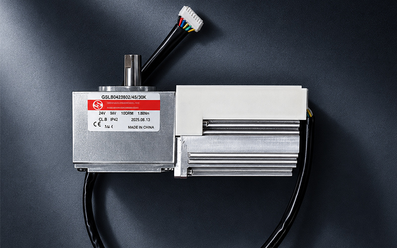
At a Glance
- Client
- Massage & rehabilitation bed manufacturer
- Industry
- Rehabilitation and wellness equipment
- Application
- Positioning axes — backrest, leg section, height, table travel
- Products
- Low-speed BLDC gear motor with FOC controller
- Drive train
- 230:1 reduction, approx. 10 r/min output
- Outcome
- 38.9 dB · 3.00% deviation · +15% rigidity
Customer Background
On a therapy bed the drive sits a few tens of centimetres from the patient’s ear, which makes noise and motion quality part of the product rather than a side effect of it.
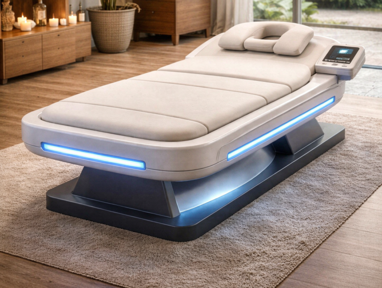
A motorised therapy bed is adjusted many times during a single treatment: the backrest, the leg section, the table height, and on some models the whole table travel, all move while the patient is lying on the surface. Every one of those movements is produced by an electric drive fixed to the frame, and every one of them is felt through the upholstery and heard at close range. That is what separates this application from general positioning duty: the drive is judged by the person on the bed, not by a machine operator standing next to it.
Bed builders usually start from a standard motor catalogue and deal with noise and smoothness late, adding insulation and tuning parameters once the mechanics are fixed. The approach costs more in this application than it looks, because the movement is slow and the torque is high: the motor ends up working far from its comfortable range, and three separate paths — friction and vibration from rotation, torque ripple from commutation, and resonance radiated by the controller housing — all arrive at the same complaint. Comparing motors on a common basis is where this starts. Rating and performance of rotating electrical machines are defined in IEC 60034-1, and a noise figure or a speed-deviation figure only means the same thing on two datasheets when both are quoted on that basis.
This project therefore began with figures rather than with a motor model. The customer’s requirement document set a maximum running noise of 40 dB or less, measured at 15 cm with 32 dB of background noise in the room, and a maximum speed deviation of 5% or better on the moving axis. It also asked for the acoustic and speed-torque results to be shown unit by unit on three pre-production assemblies, following the appliance noise test code of IEC 60704-1, instead of a single best-case reading from a development bench.
The Engineering Challenges
Three performance figures and one delivery condition, all written into the requirement document before a motor was chosen.
AAcoustic comfort
- Target: maximum running noise of 40 dB or below, measured at 15 cm with a 32 dB ambient level in the room.
- Baseline: the drive measured 42.1 dB before the project — 3 dB at the ear, which is not something insulation alone delivers.
- Three sources, one complaint: mechanical friction and vibration, electromagnetic torque ripple, and resonance re-radiated by the controller housing all reach the user through the same surface.
BMotion accuracy
- Requirement: maximum speed deviation of the moving axis within 5%, the figure the industry treats as normal for this class of equipment.
- Baseline: 4.80% measured before the project.
- Why it matters: on a bed, a speed ripple is not an electrical detail. A change of speed is felt as a jolt, and a hesitation reads to the patient as a mechanical fault.
COverload rigidity
- Load changes constantly: patients of different mass get on and off, and posture changes load the axis abruptly and unevenly.
- Requirement: a shallower speed-torque curve, so that speed falls less when the load rises rather than dropping away under pressure.
- Evidence required: the curve itself, measured on the sample, not a single rated operating point.
DUnit-to-unit consistency
- Three assemblies, measured individually: speed-torque curve and noise for each pre-production unit, not an average.
- Reason: one good prototype says nothing about a production batch, and the requirement was written to expose spread while it was still cheap to fix.
- Acceptance: every unit inside the noise target, with the three curves close enough to be described as the same product.
Products & Solution Adopted
A low-speed brushless gear motor, a sine-wave FOC controller, and a rebuilt magnetic circuit — specified from the output speed backwards. It builds on the same brushless gear motor platform Greensky supplies for other low-speed positioning duties.
Low-Speed BLDC Gear Motor
Sized for the movement rather than for the motor: the axis turns at about 10 r/min and the torque comes from the reduction ratio, so friction and vibration start from a low-speed operating point.
FOC Sine-Wave Controller
Field-oriented control holds the phase current close to a sine, so commutation spikes never excite torque ripple in the structure; a damping block in the controller housing stops what remains from being amplified by the enclosure.
Rewound Magnetic Circuit
Winding turns and winding scheme were rebuilt so the rated point sits near 10 r/min and the speed-torque curve flattens — the change that produced most of the gain in overload rigidity.
Starting from speed rather than from a larger motor is what makes this drive quiet. Friction and structure-borne vibration in a small gearmotor rise with rotational speed, so an axis that needs a few r/min and a large torque is better served by a high reduction ratio than by a fast motor that is slowed down afterwards: at 230:1 the output turns at about 10 r/min while the motor stays in a range where it works efficiently. The trade is that the motor now operates in a low-speed, high-torque region where torque ripple is more visible at the output, which is why the drive was specified as a low-voltage DC power drive system together with its controller, on the rating basis of IEC 61800-1, rather than as a motor on its own.
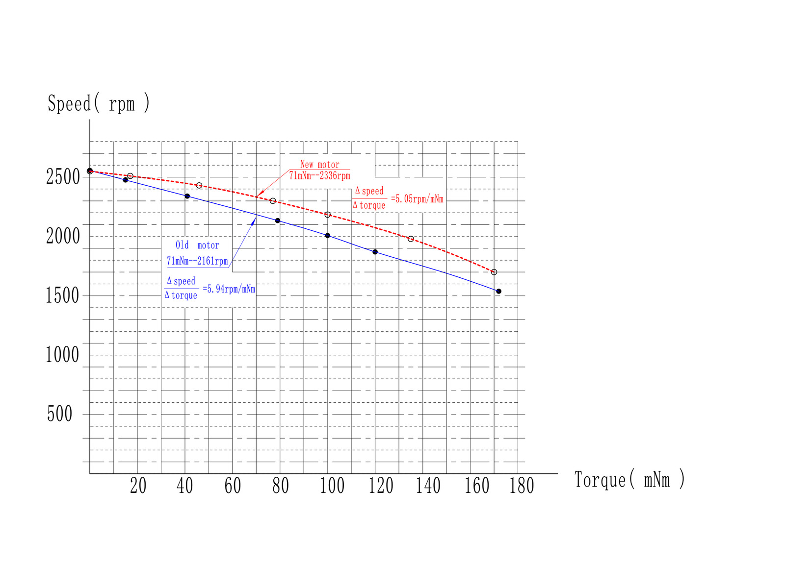
Two paths remain after the speed is set. The first is electromagnetic: field-oriented control keeps the current waveform close to a sine, so the current spikes of block commutation — and the torque ripple they generate — are removed at the source instead of being absorbed afterwards. The second is structural: a damping block inside the controller housing interrupts the path along which small vibrations travel into the housing surface, which is where high-frequency resonance would otherwise be amplified and re-radiated towards the user. Because the controller and motor act as one unit here, electromagnetic compatibility is assessed for the drive system as a whole, to IEC 61800-3. The final change was in the winding. Turns and winding scheme were rebuilt to stabilise the rated speed near 10 r/min and to flatten the speed-torque curve, which took the dynamic slope from 5.94 to 5.05 rpm/mN·m and the maximum speed deviation of the moving axis to 3.00%.
Specification as supplied: GSBLD42S24D40L-S230K
The drive that ran on the three pre-production beds, quoted the way the specification sheet states it: 24 V DC, 230:1, 10 rpm at 10 N·m, on the dedicated controller. Figures are the ones the customer received in the approval document (Rev A01), not catalogue values.
| Motor and gearbox | |
|---|---|
| Model | GSBLD42S24D40L-S230K |
| Motor type | Brushless DC, inner rotor, 3-phase / 8-pole |
| Rated voltage | 24 V DC (21–30 V DC) |
| Reduction ratio | 230:1 |
| Direction of rotation | CCW, viewed from the shaft end |
| Mass | 1.2 kg (1200 ± 10 g), gearbox included |
| Performance at the output | |
| No-load speed | 12 rpm ± 10% |
| Rated speed | 10 rpm ± 10% |
| Rated torque | 10 N·m |
| No-load current | 0.5 A max |
| Rated current | 2.2 A max |
| Line resistance | 1.17 Ω ± 10% |
| Line inductance | 0.726 mH ± 5% |
| Insulation | |
| Insulation class | Class F |
| Withstand voltage | 300 V AC for 60 s, leakage current ≤ 5 mA |
| Insulation resistance | ≥ 10 MΩ at 250 V DC |
| Environment | |
| Operating | −5 to +40 °C, 10–85% RH, non-condensing |
| Storage | −20 to +70 °C, 10–85% RH, non-condensing |
| Compliance | |
| Safety basis | Designed to the Electrical Appliance and Material Safety Law (Japan). The motor as a standalone product is not certified under that law. |
| Appliance certification | Not certified to IEC 60335-1 or IEC 60601-1; compliance is assessed on the finished bed. |
Values are quoted at 24 V DC under the dedicated controller, at 25 °C unless stated otherwise. Torque is stated at the gearbox output; motor-only test points are on the specification sheet.
| Wire | I/O | Function | Level / behaviour |
|---|---|---|---|
| Red | Power | 24V supply | Rated voltage |
| Black | Power | Power ground | — |
| White | Power | Signal ground | — |
| Yellow | In | Run / Brake | 0 V = brake, 3.3 V = run |
| Blue | In | Direction | 3.3 V = CW, 0 V = CCW |
| Green | In | Speed control | 100 Hz PWM: 10% duty → 0.48 rpm, 90% duty → 10 rpm |
| Orange | Out | Tachometer | 1 pulse per revolution, 3.3 V amplitude |
| Purple | Out | Alarm | 0 V = fault, 3.3 V = normal |
Logic level is 3.3 V on all signal wires — a 5 V or 24 V control board needs level shifting. Speed is set by PWM duty at 100 Hz, and the tachometer output closes the loop at one pulse per revolution.
Not specified in this datasheet — confirm before design freeze
These parameters are decided per application. We would rather name them than leave a gap a buyer discovers at the prototype stage:
- Ingress protection (IP) rating
- Duty cycle (S1 / S2 / intermittent)
- Service life and L10 rating
- Output-shaft backlash
- Permissible axial and radial load
- Holding torque and brake type
How We Implemented It
From the customer’s requirement document to a drive that three separate assemblies could reproduce.
Noise baseline and source split
The existing drive was measured at 42.1 dB under the agreed conditions, and the result was separated into mechanical, electromagnetic and structural contributions so that each change could be judged on its own instead of as part of one blanket improvement.
Low-speed operating point
Rated output speed was fixed at about 10 r/min and the reduction ratio at 230:1. This single decision defines the motor’s working range, and with it the rotor, the magnets and the winding that had to be designed around it.
FOC tuning
The controller was set up for sine-wave current with commutation spikes suppressed, removing the electromagnetic source of torque ripple from the assembly rather than damping it after the fact.
Housing damping block
A damping block was added inside the controller housing to break the transmission path into the shell, so that the enclosure no longer re-radiates high-frequency resonance as its own noise.
Winding redesign and three-unit validation
Winding turns and scheme were rebuilt, then the three pre-production units were measured one by one for speed-torque curve and noise, and the results were compared rather than averaged.
Requirements Met
The four figures the drive was specified and validated against, each measured on the assembly.
| Requirement | Specified limit | How the drive meets it | Reference |
|---|---|---|---|
| Maximum running noise | ≤ 40 dB | 38.9 dB measured on the assembly at 15 cm with a 32 dB ambient level. | Customer requirement |
| Noise before the project | 42.1 dB | Baseline measured under the same conditions; the 3 dB reduction was reached by design, not by added insulation. | Baseline measurement |
| Moving-axis speed deviation | ≤ 5% (industry norm) | 3.00% maximum, down from 4.80% before the winding change. | Customer requirement |
| Rated output speed | approx. 10 r/min | Held by the 230:1 reduction together with the rewound motor. | Customer requirement |
| Dynamic slope of the curve | Δspeed/Δtorque, flatter than baseline | 5.05 rpm/mN·m, down from 5.94 — speed falls less as load rises. | Prototype test report |
| Speed at 71 mN·m | Higher than baseline | 2,336 r/min against 2,161 r/min before the change. | Prototype test report |
| Overload rigidity | +15% on a single motor | The flatter slope raises the torque the drive carries before speed collapses under load. | Prototype test report |
| Noise measurement basis | 15 cm, 32 dB ambient | Measured to the conditions agreed with the customer, on the appliance noise test code. | IEC 60704-1 |
| Rating basis of the motor | One common basis | Rated and compared on the same definition of rating and performance. | IEC 60034-1 |
| Drive system scope | Low-voltage DC PDS | Motor and FOC controller specified together as one power drive system. | IEC 61800-1 |
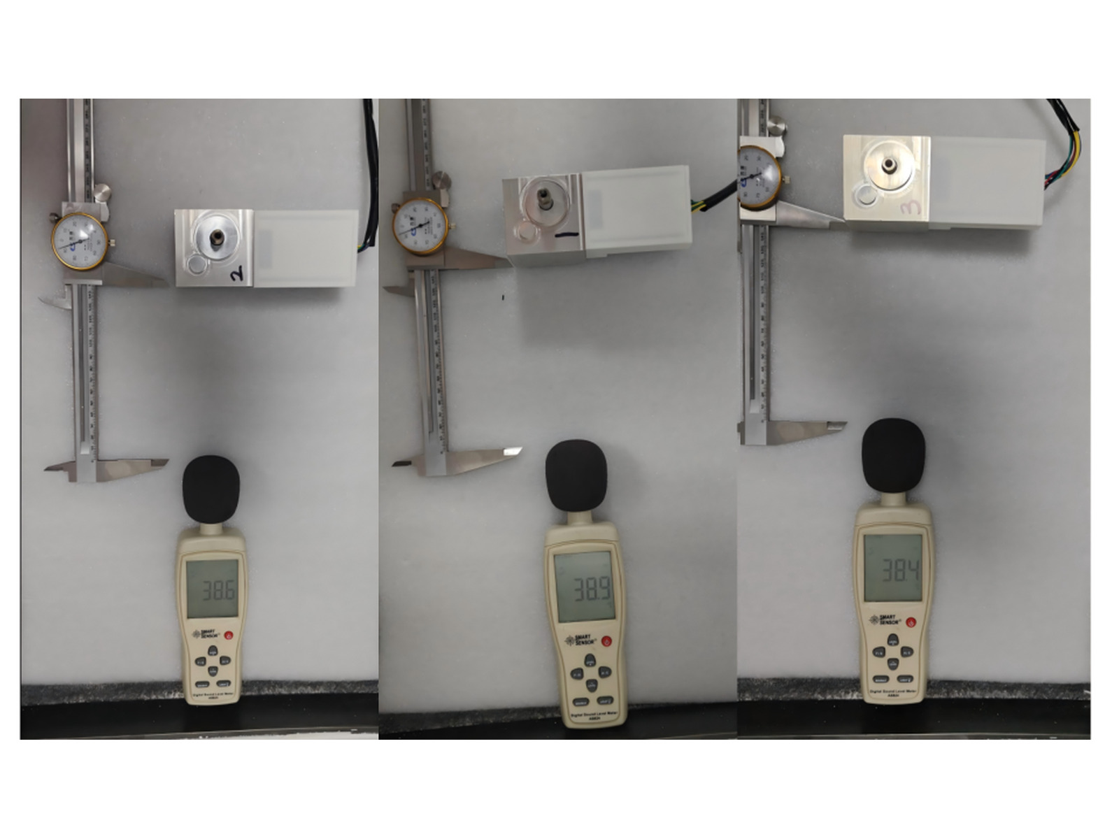
| Unit validation | 3 pre-production assemblies | 38.6 / 38.9 / 38.4 dB, with the speed-torque curve taken on each unit. | Prototype test report |
The figure the customer can build a product around is not 38.9 dB on its own but the spread behind it: three assemblies measured 38.6, 38.9 and 38.4 dB under identical conditions, and each of them gave a speed-torque curve inside the same envelope. Reaching a noise target on one bench sample is a laboratory result. Reaching it on three consecutive pre-production units is a specification the bed can be manufactured to.
Why This Drive Suits Therapy Bed Duty
Four points that decide the outcome in quiet positioning applications.
1Quiet starts at the operating point
- Friction and structure-borne vibration rise with rotational speed, so an axis driven at 10 r/min generates far less of both than the same axis driven fast and geared down later.
- Insulation and absorbers act on noise that already exists, and the space available inside a bed frame limits how much they can do.
- Choosing the reduction ratio is therefore an acoustic decision as much as a mechanical one.
2Sine-wave current removes the electromagnetic source
- Block commutation produces current spikes, and those spikes excite torque ripple that reaches the bed frame as vibration.
- Field-oriented control holds the current close to a sine, so the excitation is removed rather than damped downstream.
- What remains is small enough for a damping block in the controller housing to deal with; without the control change, the same block would only be masking part of the problem.
3Rigidity is a slope, not a power rating
- What the patient feels is how far speed drops when load rises, which is described by Δspeed/Δtorque rather than by rated power.
- A flatter curve — 5.05 instead of 5.94 rpm/mN·m — means the axis keeps its pace when a heavier patient sits down or changes position.
- A larger motor does not automatically flatten the curve; in this project the gain came from the winding, not from the frame size.
4Consistency decides whether it ships
- Three pre-production assemblies were measured individually, and the readings stayed inside 1 dB of each other.
- Curves taken per unit catch winding and assembly variation while it is still a process question rather than a field complaint.
- Which safety framework the finished bed falls under depends on its route to market: household and similar appliances are covered by IEC 60335-1, medical electrical equipment by IEC 60601-1, and the drive has to be specified with that route in mind.
Specifying a drive for a therapy bed, examination chair or positioning axis?
Send us your noise target with its measurement conditions, the speed-deviation limit, load cases and duty cycle — we will propose a matched low-speed brushless motor, controller and reduction.
Start Your Application Case
Share your application, required torque and speed, duty cycle and acoustic target — our engineers respond within 24 hours with a tailored motor proposal.
Greensky Power Co., Ltd.
Email: mkt@greensky-power.com
Tel: +86 5718819 5488
Customized Service: Yes
GSBLD42S24D40L-S230K · Rev A01 · PDF 480 KB