
Choosing an Air Compressor Motor: Load, Starting and Duty
Many articles about compressor motors focus on the industries that use compressed air. For motor selection, the compressor’s operating conditions are more useful: the torque required by the airend, the starting conditions after the contactor closes, and the hours spent at part load over a year.
Quick Answer
Compressor motor selection involves more than the kilowatt rating. Consider the shaft power at rated discharge pressure, the torque needed at startup, and the duty cycle. For a 1.05 m³/min machine at 8 bar, shaft power is about 7.3 kW. Startup torque is lower when the compressor is unloaded and may be roughly twice rated if a leaking check valve leaves pressure in the head. Duty also varies: a piston unit cycles, a screw unit may run continuously with four to six starts per hour, and a variable-speed unit may spend much of the year at 40 percent load. A 7.5 kW motor could be selected for each, but the other requirements decide whether it suits.
- A compressor is a load, not an industry
- Four compressor families, four motor duties
- Where the kilowatts go: a specific-power budget
- What motor efficiency actually buys
- Starting is the constraint, not running
- Load/unload or variable speed
- The motor in a VSD compressor is not a standard motor
- 40 °C, 1,000 m and a hot container
- Flange, shaft and coupling
- A worked example: 7.5 kW at 8 bar
- Six specification mistakes
- What to put on the enquiry
- References
- FAQ
A Compressor Is a Load, Not an Industry
Grouping compressors by the industries that use them can obscure the details a motor supplier needs. Two machines serving the same tool, such as a nail gun, can have very different power ratings. Motor selection depends on the compressor’s duty profile, which is shaped by its type and operating pattern.
Three load characteristics affect motor selection. Compression torque changes with the pressure ratio, so the same motor may deliver less flow at 10 bar than at 8 bar. At a fixed discharge pressure, shaft power and mass flow are approximately proportional, so compressor loads should not be treated like fan loads when selecting a drive. Starting conditions also matter because the motor and compressor are far from steady-state operation just after the contactor closes.
Compare the compressor’s operating requirements with the motor data. Rated output, speed and current describe a particular operating point, while a compressor may spend much of its time at other points. The torque-speed plane helps show the relationship: the motor produces a torque curve, the load requires one, and operation depends on where the two curves intersect.
Four Compressor Families, Four Motor Duties
Compressor type affects motor speed, mounting, starting load and the components most exposed to failure. These requirements differ across compressor families, so their motors are not automatically interchangeable.
| Compressor family | Typical motor | Speed and drive | Start condition | What fails first |
|---|---|---|---|---|
| Reciprocating (piston), portable | 0.75–7.5 kW, 1-phase or 3-phase induction | 2-pole, V-belt to a flywheel | Unloaded by a head unloader | Motor front bearing from belt tension |
| Reciprocating, industrial | 4–75 kW, 3-phase induction | 4- or 6-pole, belt or direct | Unloaded, high inertia flywheel | Valve plate, then motor insulation from cycling |
| Rotary screw | 5.5–250 kW, 3-phase induction | 2-pole direct on the airend, or 4-pole through gears | Inlet valve closed and blowdown | Coupling element, airend bearings |
| Scroll | 1–7.5 kW, 3-phase or 1-phase | 2-pole direct, often tank-mounted | Low residual pressure only | Tip seals, then motor from short cycling |
| Centrifugal (dynamic) | 100 kW and up, 2-pole through a step-up gear, or high-speed PM | Integral gearbox, 3,000/3,600 rpm input | Inlet guide vane closed, blow-off open | Surge damage, not the motor |
Reciprocating: the flywheel changes the motor
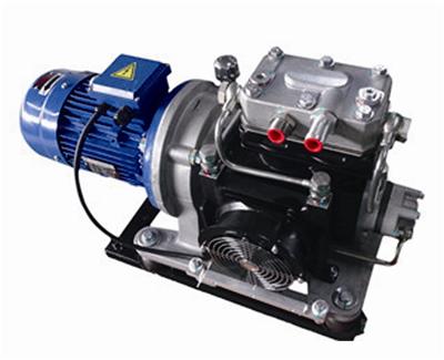
A belt-driven piston compressor uses a flywheel between the motor and crankshaft. The flywheel smooths the torque pulsation from a single-acting cylinder and stores energy. If the unloader empties the head, the motor’s starting load is closer to a no-load start than the piston alone might suggest.
Belt tension places a radial load on the motor’s front bearing. Excessive tension can contribute to early bearing failure on small compressors; the first sign may be noise, followed by seizure, and the motor is sometimes blamed. Even with correct tension, the bearing carries a belt load. Compressor-duty motors may therefore use a heavier front bearing than a general-purpose motor in the same frame.
Rotary screw: the flange is the interface
Screw compressors commonly connect the motor to the airend through a bell housing. In these assemblies, the flange and shaft are central to the fit; IEC B5 or B35 and NEMA C-face are common mounting styles in their respective markets. The register diameter and bolt circle depend on the frame size. A foot-mounted motor with matching power and speed may still not fit the bell housing. An adapter adds cost and alignment considerations, so compare it with sourcing the correct motor.
With a 2-pole motor, the airend runs at motor speed, about 2,900 rpm at 50 Hz or 3,500 rpm at 60 Hz. Larger units may use a 4-pole motor and timing gears to reach the required rotor speed. These arrangements have fixed operating speeds, with flow set by the airend displacement. A variable-speed drive changes the motor requirements, as discussed below.
Scroll: quiet, and thermally fragile
Scroll compressors are often selected for low noise and oil-free air. Smaller packages commonly use a tank-mounted 2-pole motor that runs continuously. The scroll set has little reciprocating mass, so startup is relatively gentle; some machines start and stop in response to pressure rather than running unloaded.
A scroll compressor with a small receiver may cycle twenty or thirty times an hour. Each start adds thermal stress to the winding, and short cycling can contribute to early motor failure. A larger receiver or minimum run timer may reduce cycling; a larger motor does not correct the control issue.
Centrifugal: dynamic, not positive displacement
A centrifugal compressor is a dynamic machine, not a positive-displacement machine. Positive-displacement compressors trap and compress a fixed volume; a centrifugal compressor accelerates gas with an impeller and converts velocity into pressure in a diffuser. Their load curves differ. The article describes centrifugal compressors as starting with the inlet guide vane closed and unloading through a blow-off valve.
Above roughly 100 kW these machines usually run through a step-up gearbox, with a 2-pole motor as the prime mover. The newest generation uses a high-speed permanent-magnet motor on a drive, with no gearbox at all — the one place in this family where a brushless machine competes directly with an induction motor. The comparison is the same one that applies elsewhere: BLDC versus induction comes down to duty and volume, not to a universal winner.

Where the Kilowatts Go: A Specific-Power Budget
Calculate the required shaft power before selecting a motor. The example below uses a compressor delivering 1.05 m³/min of free air at 8 bar gauge, with inlet air at 20 °C at sea level. The inlet pressure is 1 bar absolute and the discharge pressure is 9 bar absolute, giving a pressure ratio of 9.
The ideal isothermal power is the pressure times the volume flow times the logarithm of the ratio. In SI units that is 100,000 Pa × 0.0175 m³/s × ln 9, which gives 3.85 kW. That is the theoretical floor: the power a perfectly cooled, frictionless machine would need. Real compression is closer to adiabatic, and the adiabatic expression with the ratio of specific heats for air gives 5.35 kW. The ratio of the two, 3.85 over 5.35, is 72 percent, which is the isentropic efficiency of this compression process.
| Stage | Value | What it represents |
|---|---|---|
| Isothermal power | 3.85 kW | Theoretical floor for 1.05 m³/min at 9:1 |
| Adiabatic power | 5.35 kW | Same flow with no heat removal |
| Isentropic efficiency | 72% | How close the process comes to the floor |
| Airend shaft power | 7.13 kW | 5.35 kW divided by a 0.75 airend efficiency |
| Motor shaft power | 7.28 kW | Allowing 98% for the coupling |
| Motor input power | 8.05 kW | Divided by 90.4%, the IE3 figure for 7.5 kW at 4-pole |
| Input specific power | 7.67 kW per m³/min | 8.05 kW divided by 1.05 m³/min, at the wall |
For a tender, the final row gives a useful comparison point: input specific power in kilowatts per cubic metre per minute at a stated pressure. Flow without pressure, or pressure without the input power, is not enough to compare machines. The motor must supply the corresponding shaft torque; at 2,900 rpm, 7.28 kW corresponds to 24.0 N·m. See torque behind that power.
Gauge pressure and pressure ratio describe different things. Increasing pressure from 8 to 10 bar gauge sounds like a 25 percent increase, but the absolute pressure ratio rises from 9 to 11. The article estimates that shaft work rises by about 9 to 13 percent, depending on heat accounting, while flow at the same shaft power falls by roughly 8 percent. Quotes at different pressures need to be adjusted before comparing.
What Motor Efficiency Actually Buys
Motor efficiency class is easy to compare, but the example below shows how changes to the airend, coupling and motor affect specific power. It holds motor shaft power at 7.5 kW and varies one input at a time.
| What changes | Flow at 7.5 kW shaft | Specific power | Effect |
|---|---|---|---|
| Airend isentropic efficiency 0.70 | 1.01 m³/min | 7.43 | Baseline |
| Airend isentropic efficiency 0.75 | 1.08 m³/min | 6.93 | 7% less energy per m³ |
| Airend isentropic efficiency 0.78 | 1.13 m³/min | 6.67 | 10% less energy per m³ |
| Coupling 0.95 instead of 0.98 | 1.05 m³/min | 7.11 | 3% worse |
| Motor IE4 instead of IE3 | 1.05 m³/min | 7.53 | 1.8% better |
In this example, increasing airend efficiency from 0.70 to 0.78 reduces energy use by about ten percent, while changing the motor from IE3 to IE4 improves it by less than two percent. At 4,000 operating hours per year and 0.12 EUR per kWh, the estimated savings are roughly 425 EUR and 71 EUR, respectively. Both upgrades may be worthwhile, but the airend change has the larger effect in this calculation.
None of that makes efficiency class optional, because it is a legal floor rather than a preference. EU Regulation 2019/1781 sets IE3 as the minimum for three-phase induction motors from 0.75 to 1,000 kW placed on the EU market, with IE4 required for the 75 to 200 kW band since July 2023. A compressor OEM buying motors in Europe is buying in-scope products unless a specific exclusion applies, and the exclusions are narrow. The class boundaries themselves are explained in motor efficiency class.
Starting Is the Constraint, Not Running
A compressor may run reliably for months and then fail to start after maintenance. The cause can be the machine’s condition rather than a motor fault. In the first seconds after the contactor closes, the motor may draw several times its rated current, and available and required torque differ from their steady-state values.
| Starting method | Current at start | Torque available | Verdict for a compressor |
|---|---|---|---|
| Direct on line | 6.5–7.5 × rated | 2.0–2.5 × rated | Normal up to about 7.5 kW on a stiff supply |
| Star-delta | 2.2–2.5 × rated | 0.7–0.8 × rated | Works only if the unloaded start is guaranteed |
| Soft starter at 3 × rated | 3 × rated | About 0.47 × rated | Fails against trapped pressure |
| Variable-speed drive | 1.5 × rated for 60 s | 1.5 × rated | Works loaded, and gives a controlled stop |
A soft starter limits starting current, but that also reduces available torque. For an induction motor, torque is approximately proportional to the square of applied voltage. In the example, reducing current from 6.5 times rated to 3 times rated leaves about one-fifth of the direct-on-line torque. That may be enough for an unloaded compressor but not for one starting against 8 bar in the head.
The unloaded rule
Most larger compressors are designed to start without pressure on the working parts. A piston unit uses a head unloader to vent the first strokes; a screw unit closes its inlet valve and blows down the separator before startup. These systems also rely on a check valve isolating receiver pressure from the airend, and on the solenoid or diaphragm operating correctly.
If an unloader or check valve fails, the motor may start against pressure. It can draw locked-rotor current without accelerating, and the overload may trip in two to five seconds. Three consecutive attempts can heat a Class F winding enough to cause permanent damage, even if the motor still runs afterwards. Before replacing electrical components, check whether pressure remains at the head and whether blowdown occurred when the compressor stopped.
A larger motor is not a substitute for repairing a leaking check valve. It may push through and mask the fault, while subjecting the airend and coupling to starting torque beyond their design. The check valve is the failed part and costs a fraction of a motor; check and repair it before changing motor size.
Load/Unload or Variable Speed
Fixed-speed screw compressors regulate output by opening and closing the inlet valve as pressure moves through a set band. The motor continues to run during unloaded periods, so part-load energy use is full-load power multiplied by the loaded fraction, plus unload power for the remainder. For a lubricated screw compressor, unloaded power is typically 20 to 35 percent of full-load power because the rotors and oil system continue running.
| Average demand | Load/unload input | Variable speed input | Saving |
|---|---|---|---|
| 100% | 8.05 kW | 8.05 kW | 0 |
| 75% | 6.64 kW | 6.10 kW | 8% |
| 50% | 5.23 kW | 4.15 kW | 21% |
| 25% | 3.82 kW | 2.17 kW | 43% |
The fan and pump affinity laws do not directly describe a compressor holding constant discharge pressure. In this case, specific compression work changes little while mass flow falls, so power is expected to fall roughly with flow rather than with the cube of speed. A savings estimate should use the compressor’s operating profile instead of assuming an 87 percent reduction at half demand.
At 50 percent average demand, typical of a plant sized for its worst week, the example estimates that a drive saves about one kilowatt, or 3,880 kWh and 466 EUR a year at 4,000 hours. That is around six times the estimated return from an IE4 upgrade. The comparison depends on the demand profile and the assumptions used in the calculation.

The Motor in a VSD Compressor Is Not a Standard Motor
Adding a drive changes the motor’s operating conditions. At deep turn-down, check the winding insulation, bearing-current risk and cooling. If these requirements are not met, the resulting failure may look like a manufacturing defect.
Winding insulation
A PWM drive supplies a train of voltage pulses rather than a sine wave. Fast rise times and reflected waves on long motor cables can increase voltage stress at the motor terminals. The article’s 400 V example estimates pulses approaching 1,100 V. IEC 60034-18-41 covers Type I insulation systems; IEC 60034-18-42 covers Type II systems. For a long cable, Type II insulation with a dv/dt filter or output reactor may be required; confirm the combination for the drive and motor.
Specify the motor’s insulation system when it will be used with a drive. A motor suitable for direct-on-line operation may not meet the drive application’s voltage-stress requirements. Insulation testing methods are described in electric motor testing standards.
Bearing currents
Fast switching can create common-mode voltage that couples capacitively to the rotor. Bearing discharge current may erode the raceway and produce fluting, noise or bearing failure. Possible mitigations include an insulated bearing on one or both ends or a shaft-grounding ring. These measures are commonly considered above roughly frame size 90; smaller machines often operate without them. The appropriate design depends on the motor and drive system.
Cooling at low speed
A totally enclosed fan-cooled motor uses a shaft-mounted fan. At half speed, fan airflow is about half and pressure about a quarter under the fan laws. The motor may be rated for full torque at half speed yet still overheat because cooling is reduced. Deep turn-down may therefore require separate ventilation, identified as IC 416 in IEC 60034-6.
One more decision sits on the drive rather than on the motor. A compressor is a constant-torque load, so the drive must be selected on its constant-torque rating. A drive bought on its variable-torque rating, which is the number usually printed largest on the front, will be undersized for this duty. The difference between the two applications is set out in VFD motor versus normal motor, and the control behaviour itself in how a variable-speed motor works.
40 °C, 1,000 m and a Hot Container
Motor ratings assume specified operating conditions. IEC 60034-1 uses 40 °C ambient and 1,000 m altitude as reference conditions. A hot compressor room or a high-altitude site may require derating, which can explain thermal trips even when the motor appears correctly sized.
Temperature
A compressor releases substantial heat into its surroundings unless the room is ventilated or the heat is ducted away. The article describes 45 to 50 °C as common in some unventilated containers or small plant rooms. It also gives a TEFC rule of thumb of about one percent output derating per kelvin above 40 °C, making 46 °C an estimated six percent derating. Check the motor manufacturer’s data for the actual site.
A Class F insulation system with Class B temperature rise can provide thermal margin, estimated here at roughly 25 K. Specify this combination and confirm the motor’s actual design with the supplier; the available margin at a hot site depends on the complete thermal rating and may help reduce thermal trips during hot weather.
Altitude
At 2,000 m, air density is about three quarters of its sea-level value. A fan moving the same volume therefore moves less air mass and provides less cooling. The article gives a typical TEFC derating of about one percent per 100 m above 1,000 m, but the manufacturer’s derating table should govern. The compressor airend may also deliver less mass flow at altitude; that is separate from the motor’s reduced cooling.
| Site condition | Motor derating | 7.5 kW becomes |
|---|---|---|
| 40 °C, sea level | None | 7.5 kW |
| 46 °C, sea level | About 6% | 7.05 kW |
| 40 °C, 2,000 m | About 10% | 6.75 kW |
| 46 °C, 2,000 m | About 15% | 6.38 kW |
The last row is the one that explains a familiar complaint: the same model performs worse in one country than another, and nobody can find a fault. A 7.5 kW motor at 46 °C and 2,000 m has about 6.4 kW of usable output, which is less than the 7.28 kW the airend needs. The machine is not faulty; it was specified at sea level in a temperate country and installed somewhere else.
Flange, Shaft and Coupling
Electrical ratings often receive most of the attention, while mounting and shaft differences can make a replacement incompatible. On a screw compressor, the flange register and shaft are key interface dimensions.
IEC flange mounting is designated B5 for flange only and B35 for feet plus flange, with the register diameter and bolt circle fixed by frame size. NEMA equivalents are the C-face series, 56C on small frames and 143TC or 145TC on the sizes that appear on small compressors. A foot-mounted B3 motor of identical power, speed and voltage will not bolt to a bell housing, and the adapter plate that makes it fit adds an alignment tolerance and a cost that usually exceed the difference in motor price.
The shaft end also needs to match the coupling. A flexible coupling can accommodate limited angular and parallel misalignment, but not axial preload. If assembly pushes the motor against the airend bearing, both bearings may be preloaded and vibration can result. At 2,900 rpm, once-per-revolution vibration is about 48 Hz and may be felt in the pipework before it is heard.
Two further mechanical points belong in the same conversation. Speed is not interchangeable: a 4-pole motor at 1,450 rpm cannot replace a 2-pole at 2,900 rpm without changing the pulley ratio or the gear set, and the relationship between poles and speed is set out in number of poles in a motor. And on belt-driven units the motor bearing carries the belt load, so a replacement motor with a lighter bearing than the original will fail early even though every nameplate figure matches.
A Worked Example: 7.5 kW at 8 bar
Putting the pieces together for the machine used above: 1.05 m³/min of free air at 8 bar gauge, lubricated screw, direct-coupled, in a plant room that reaches 46 °C in summer, running 4,000 hours a year with an average demand near 55 percent.
| Parameter | Specification | Why this value |
|---|---|---|
| Output | 7.5 kW | 7.28 kW calculated, 3 percent margin |
| Speed and poles | 2,900 rpm, 4-pole at 50 Hz, or 3,500 rpm at 60 Hz | Direct coupling to the airend |
| Voltage | 400 V delta, 50 Hz, or 460 V, 60 Hz | Site supply; check the actual terminal voltage |
| Mounting | IEC B5 flange, or NEMA 145TC | Bolts to the airend bell housing |
| Insulation | Class F, Class B rise | Leaves margin for a 46 °C room |
| Protection | Three PTC thermistors in series, plus overload | Detects a hot winding before the overload does |
| Enclosure | IP55, TEFC | Dust and washdown in a plant room |
| Efficiency | IE3 minimum, IE4 if the volume justifies it | Legal floor in the EU; 1.8 percent is the real gain |
| Duty | S1, 4 to 6 starts per hour maximum | Thermal cycling limit of the winding and contactor |
Check the motor’s usable output at the actual site conditions. At 46 °C and sea level, the example estimates about 7.05 kW available against a 7.28 kW demand, so the stated output does not cover the calculated demand. The margin is also insufficient if the room reaches 50 °C. The article suggests moving to a 9 kW motor or ducting the room; compare these options against expected operating conditions.
Where the machine is a small reciprocating unit instead, the same logic gives a different answer: 4-pole, belt-driven, foot-mounted, with a heavier front bearing and a service factor that assumes cycling. That is a general-purpose motor with a compressor duty attached, and the boundary conditions for the category are in general purpose motor. Portable 12 V and 24 V packages are a separate case again, built around permanent-magnet DC motors.
Six Specification Mistakes
| Mistake | What happens | Correct approach |
|---|---|---|
| Sizing on the compressor’s kW badge | The badge is input power; the motor is asked for shaft power | Calculate shaft power, or divide the badge by motor efficiency |
| Ignoring breakaway torque | Motor stalls on the first start after a shutdown | Confirm the unloader and check valve work; size for the loaded case if they cannot be guaranteed |
| Soft starter on a machine that may start loaded | Trips at 3 × current with a fifth of the torque | Use a drive, or fix the unloader first |
| Standard motor on a deep turn-down drive | Insulation failure or bearing fluting within two years | Specify Type II insulation, insulated bearing, separate ventilation |
| Rating at 40 °C in a 50 °C room | Thermal trips every summer, blamed on the motor | Derate for the real ambient, or specify Class F with Class B rise |
| Using service factor as margin | Continuous running at 1.15 shortens insulation life | Size at 1.0 and keep the service factor for transient overload |
The sixth row differs by region. NEMA motors are commonly sold with a service factor of 1.15, which permits a defined overload; that allowance is not a licence to run at 115 percent for years. Insulation ages on temperature, and temperature follows load, so a motor specified at 1.0 with a correctly calculated shaft power outlasts one run continuously at its limit.
What to Put on the Enquiry
Providing these eight details can help a supplier prepare a quotation. Missing information may require follow-up and can leave assumptions unresolved.
- Free air delivery and discharge pressure, both stated, because neither is meaningful alone.
- Compressor type and drive arrangement: screw or piston, direct or belt, and the airend speed if it is geared.
- Shaft power calculated, not copied from a badge, with the isentropic efficiency you are assuming.
- Starting method: direct on line, star-delta, soft starter or drive, and whether a loaded start is possible.
- Starts per hour and annual running hours, which together decide the thermal duty.
- Site ambient and altitude, worst case rather than average, since derating is set by the worst hour.
- Mounting and shaft: flange designation, register diameter, shaft diameter and key, coupling type.
- Efficiency class and any certification the destination market requires, stated as a standard rather than a label.
Two details deserve particular attention: calculate shaft power instead of copying a nameplate value, and confirm whether a loaded start is possible. These checks can identify sizing or startup issues before the order. Apply the same approach to other driven loads on the skid; see the related pump motor discussion.
References
- International Electrotechnical Commission. (2022). IEC 60034-1:2022 — Rotating electrical machines, Part 1: Rating and performance. IEC. https://webstore.iec.ch/en/publication/65446
- International Electrotechnical Commission. (2025). IEC 60034-30-1:2025 — Efficiency classes of line operated AC motors (IE code). IEC. https://webstore.iec.ch/en/publication/91195
- International Electrotechnical Commission. (2014). IEC 60034-2-1:2014 — Standard methods for determining losses and efficiency from tests. IEC. https://webstore.iec.ch/en/publication/121
- International Electrotechnical Commission. (2013). IEC 60529:1989+AMD2:2013 — Degrees of protection provided by enclosures (IP code). IEC. https://webstore.iec.ch/en/publication/2452
- International Electrotechnical Commission. (2016). IEC TS 60034-30-2:2016 — Efficiency classes of variable speed AC motors (IE code). IEC. https://webstore.iec.ch/en/publication/30830
- International Organization for Standardization. (2009). ISO 1217:2009 — Displacement compressors: Acceptance tests. ISO. https://www.iso.org/standard/44769.html
- European Parliament and Council. (2019). Regulation (EU) 2019/1781 laying down ecodesign requirements for electric motors and variable speed drives. EUR-Lex. https://eur-lex.europa.eu/eli/reg/2019/1781/oj
- European Parliament and Council. (2014). Directive 2014/68/EU on pressure equipment. EUR-Lex. https://eur-lex.europa.eu/eli/dir/2014/68/oj
- National Electrical Manufacturers Association. (2021). NEMA MG 1 — Motors and Generators. NEMA. https://www.nema.org/standards
- U.S. Department of Energy. (2024). Motor Systems — Advanced Manufacturing Office. DOE. https://www.energy.gov/eere/amo/motor-systems
FAQ
Q: What type of motor is used in an air compressor?
Almost every mains-powered compressor uses a three-phase squirrel-cage induction motor. Screw units commonly use 2-pole motors at 2,900 rpm on 50 Hz or 3,500 rpm on 60 Hz, direct-coupled to the airend; belt-driven piston units use 4-pole motors at 1,450 or 1,750 rpm. Small portable and vehicle compressors may use 12 V or 24 V permanent-magnet DC motors. See the brushed DC motor overview.
Q: Why does my compressor motor trip when it starts?
A common cause is pressure remaining in the head at startup. The compressor uses a head unloader, or a closed inlet valve and check valve, to isolate the airend from receiver pressure. If a check valve leaks or an unloader fails, the motor may draw locked-rotor current, fail to accelerate and trip. Check head pressure before replacing electrical components.
Q: Can I use a soft starter on a compressor motor?
A soft starter may work if the compressor is reliably unloaded at startup. In the example, limiting current to three times rated leaves about one-fifth of direct-on-line torque, which is insufficient if the compressor must break away against 8 bar in the head. A drive can provide 150 percent torque while limiting current and gives a controlled stop rather than a coast; verify the required ratings for the compressor and drive.
Q: Why is a compressor motor rated at 40 °C?
Forty degrees Celsius and 1,000 m are the reference service conditions in IEC 60034-1. A compressor room in summer often reaches 45 to 50 °C, so the motor is outside its rating on the hottest days of the year. The usual rule is about one percent of output per kelvin above 40, and it compounds with altitude derating. Specifying Class F insulation with Class B rise buys roughly 25 K of margin at little cost.
Q: Does a variable-speed compressor need a special motor?
Often, the motor needs to be selected for three drive-related conditions. IEC 60034-18-42 Type II winding insulation may be required for PWM voltage stress, particularly with a long cable. Common-mode shaft voltage may call for an insulated bearing or grounding ring on larger frames. Reduced shaft-fan cooling at low speed can make separate ventilation, designated IC 416, necessary for deep turn-down. Confirm these requirements for the motor and drive; a standard TEFC motor is not automatically a drop-in substitute.
Q: Is a bigger motor a safe margin on a compressor?
A larger motor may add cost without addressing startup pressure or a hot installation. Oversizing can also leave a motor operating at light load, where power factor and efficiency may be lower. Size the motor from the required shaft power and appropriate margin, then compare investments such as airend efficiency or leak repair. The article estimates that a 20 percent distribution leak costs about ten times the savings from an IE4 upgrade; verify that comparison against site data.
Greensky Power supplies three-phase induction and brushless DC motors for compressor, pump and blower applications, including flange-mounted screw-compressor motors with Class F insulation and PTC protection. For a sizing enquiry, provide the free air delivery, discharge pressure and site ambient. Contact the engineering team.