
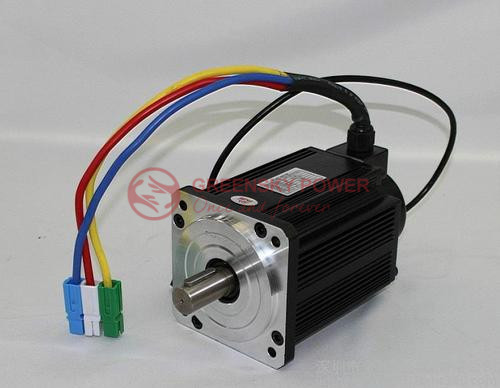
Why Do Brushless DC Motors Have 3 Wires? (Phase, Wiring & Standards Explained)
[ez-toc]
Quick Answer: Brushless DC (BLDC) motors use three wires because the stator is built from three separate phase windings—labeled U, V, and W (or A, B, C). An electronic controller (ESC) energizes these phases in a precise sequence, each offset by 120°, to create a rotating magnetic field that pulls the permanent-magnet rotor around. Three phases are the mathematical minimum for smooth, self-starting, dead-spot-free rotation: a two-wire system stalls in magnetic dead spots, while a four- or five-wire system adds cost and control complexity with diminishing returns (IEC 60034-1; NEMA MG 1). The three wires are not power/control/ground—they are all phase conductors, and swapping any two simply reverses rotation direction.
Tip: If you’re not familiar with bldc motor manufacturers, read our detailed guide about Chinese bldc motor manufacturers to learn more about bldc motor manufacturers.
What Is a Brushless DC Motor and Why Does It Need Three Wires?
A brushless DC motor is a synchronous machine in which the copper windings form the stator and the permanent magnets form the rotor. Instead of mechanical brushes and a commutator flipping current direction, an external electronic controller performs electronic commutation—switching current between windings at exactly the right moment based on rotor position (Hall sensors or sensorless back-EMF detection).
The three external wires are the three phase terminals brought out from the stator. They correspond to three sets of coils physically distributed around the stator so that their magnetic axes are spaced 120° apart electrically. Standard phase labeling follows IEC 60034-1 convention: U, V, W (also written A, B, C in North American literature).
Three Wires, Not Two or Four
The number of wires is a direct consequence of the number of phases:
- Two wires (brushed DC): Current direction is reversed mechanically by the commutator. The motor can “push” itself past dead spots because the brushes physically break and remake contact.
- Three wires (BLDC, standard): Each phase is energized in sequence to produce a magnetic wave that travels 360° around the stator. This is the minimum configuration that guarantees continuous torque in every rotor position.
- Four, five, or six phases: Produce an even smoother field, but each extra phase needs another wire, another coil set, and another switching stage in the controller—complexity that rarely pays off for general-purpose motion.
This is the same reason three-phase power dominates grid distribution worldwide: it is the lowest-cost way to deliver rotation without a mechanical commutator.

How Many Wires Can a BLDC Motor Have?
A bare three-wire motor is the industry default, but real products carry more wires when feedback or thermal protection is integrated:
| Configuration | Wire Count | What the Wires Carry | Typical Use |
|---|---|---|---|
| 3-wire | 3 | Phase U, V, W only (sensorless) | Drones, cooling fans, pumps |
| 5-wire | 5 | U, V, W + Hall Vcc + Hall GND | Robotics, conveyors (shared Hall return) |
| 6-wire | 6 | U, V, W + 3 individual Hall outputs | Servo drives, precision actuators |
| 8-wire | 8 | U, V, W + Hall x3 + temperature sensor | Automotive, medical (overtemp protection) |
So when an engineer asks “why 3 wires,” the precise answer is: three phase conductors are mandatory for the rotating field; additional wires are optional feedback/thermal channels, not part of the power path.
How a 3-Wire BLDC Motor Produces Rotation: Step by Step
- DC supply input. A battery or DC bus feeds the controller (e.g., 12 V, 24 V, or 48 V). The BLDC itself cannot run from DC alone—it needs the controller to convert it.
- DC → three-phase PWM. The controller’s inverter (six MOSFETs/IGBTs) chops the DC bus into three pulse-width-modulated phase voltages.
- 120° sequential energization. At any instant, two of the three phases conduct while the third is off (six-step, or trapezoidal, commutation). The active pair shifts every 60° of electrical rotation, advancing the field in 60° steps.
- Rotating magnetic field. The sequenced currents generate a magnetic field vector that sweeps around the stator. FAULHABER’s design documentation describes the stator field as “traveling in a circle” to pull the rotor magnet along.
- Rotor follows + feedback. Hall sensors (in 5/6/8-wire motors) report rotor angle so the controller fires the next pair at the exact right moment. In sensorless designs, the controller infers position from the floating phase’s back-EMF.
For higher smoothness, sinusoidal commutation (FOC) drives all three windings with currents shifted 120° and shaped as sine waves—maxon notes this eliminates torque ripple and yields ~5% more continuous torque than block commutation.
BLDC 3-Wire vs Brushed DC 2-Wire vs Stepper 4-Wire
| Feature | Brushed DC (2 wires) | BLDC (3 wires) | Stepper (4–6 wires) |
|---|---|---|---|
| Commutation | Mechanical (brushes) | Electronic (ESC) | Electronic (driver) |
| Phases | 1 (split by commutator) | 3 (U/V/W) | 2 (bipolar) or more |
| Wear parts | Brushes & commutator | None | None |
| Typical efficiency | 75–85% | 85–94% | 40–70% |
| Dead-spot risk | None (mechanical) | None (3-phase) | None (multi-phase) |
| Best for | Low-cost, simple | High-speed, high-efficiency | Open-loop positioning |
| Controller cost | Low (none) | Medium–High | Medium |
Engineering Data: Wiring Topology, Efficiency & Temperature Limits
Star (Wye, Y) vs Delta (Δ) Internal Connection
Inside the motor, the three phase windings can be connected in two ways. maxon’s EC motor engineering notes state the rhombic winding is “divided into three partial windings, each shifted by 120°” and “can be connected in two different manners—’Y’ or ‘Δ’. This changes the speed and torque inversely proportional by the factor √3.”
| Parameter | Star (Y) Connection | Delta (Δ) Connection |
|---|---|---|
| Phase voltage | V_phase = V_line / √3 | V_phase = V_line |
| Phase current | I_phase = I_line | I_phase = I_line / √3 |
| Speed constant | Lower (higher torque constant) | Higher (used in high-speed motors) |
| Torque constant | Higher | Lower |
| Common in | maxon EC-i, EC-flat | High-speed maxon EC, RC motors |
IEC 60034-30-1 Efficiency Classes (IE1–IE5)
BLDC motors routinely operate in the IE4–IE5 band. The table below maps the international efficiency classes referenced in IEC 60034-30-1 and the equivalent NEMA tiers:
| IE Class | Description | NEMA Equivalent | Typical BLDC Range |
|---|---|---|---|
| IE1 | Standard efficiency | — | <80% |
| IE2 | High efficiency | — | 80–85% |
| IE3 | Premium | NEMA Premium | 85–90% |
| IE4 | Super Premium | NEMA Super Premium | 90–93% |
| IE5 | Ultra Premium | Not yet defined by NEMA | 93–96% |
Real-world examples from manufacturer data sheets: Faulhaber 3272G036CR reaches 88% max efficiency; Siemens SIMOTICS permanent-magnet synchronous motors reach 92–94%; maxon EC-max 30 reaches ~75% at 48 V in its continuous range.
Insulation Temperature Limits (IEC 60034-1)
Winding temperature is the hard limit on a BLDC’s continuous duty. Per IEC 60034-1 thermal classes:
| Insulation Class | Max Winding Temp | Typical Application |
|---|---|---|
| Class B | 130 °C | General-purpose industrial |
| Class F | 155 °C | Siemens SIMOTICS, maxon EC (common) |
| Class H | 180 °C | Automotive, harsh environment |
Faulhaber’s CR-series windings tolerate up to 155 °C (optional), with thermal resistances Rth1 = 2.9 K/W and Rth2 = 8.9 K/W, meaning a 10 W winding loss raises temperature by roughly (2.9 + 8.9) × 10 ≈ 118 K above ambient in the insulated case.
Key Formulas for 3-Wire BLDC Design
Use these to size and verify a three-wire BLDC system:
| Quantity | Formula | Notes |
|---|---|---|
| Phase voltage (star) | Vph = Vline / √3 | Delta: Vph = Vline |
| Back-EMF | E = kE × ω | kE from data sheet (V·s/rad) |
| Electromagnetic torque | T = kT × I | kT ≈ kE in SI units |
| Three-phase copper loss | Pcu = 3 × I² × Rph | Dominant loss at rated current |
| Winding temperature rise | ΔT = Ploss × (Rth1 + Rth2) | Verify ΔT + Tamb < class limit |
| SKF bearing life | L10h = (10⁶ / 60n) × (C / P)ᵖ | p = 3 ball, 10/3 roller |
| NEMA service factor | SF = Tallow / Trated | Up to 1.15 per NEMA MG 1 |
Academic work confirms the practical impact of winding choice: Copt et al. (IEEE ECCE 2017, DOI:10.1109/ECCE.2017.8096636) show star↔delta reconfiguration reshapes the torque–speed curve, and Lee et al. (IEEE Trans. Magnetics 2024, DOI:10.1109/TMAG.2024.3465879) quantify that circulating currents in delta windings can cut efficiency by up to 18% at low speed/torque.
Best Applications for 3-Wire BLDC Motors
| Application | Why 3-Wire BLDC Fits | Typical Voltage |
|---|---|---|
| Drones / RC / hobby | High power density, sensorless OK | 11.1–22.2 V LiPo |
| Cooling fans & blowers | Low cost, long life, no brushes | 12–24 V |
| E-bikes / EVs | IE4–IE5 efficiency, regen capable | 24–48 V (up to 400 V) |
| Robotics & servo | Precise FOC, 5/6-wire + encoder | 24–48 V |
| Pumps & HVAC | Quiet, efficient, variable speed | 24–230 V |
| Medical devices | Low EMI option, sterilizable | 12–48 V |
How to Specify a 3-Wire BLDC Motor: 6-Step Selection Process
- Define load. Calculate required torque (T = F × r for linear loads) and speed (rpm).
- Pick voltage & topology. Choose 12/24/48 V and star vs delta per the speed/torque trade-off (√3 factor).
- Check efficiency class. Target IE4+ to meet the DOE 2027 rule and cut lifetime energy cost (ABB notes payback < 1 year for higher IE class).
- Verify thermal margin. Confirm ΔT = Ploss × (Rth1 + Rth2) keeps winding below its IEC 60034-1 class limit at max ambient.
- Select controller & feedback. Sensorless (3-wire) for fans; Hall/sensor (5–8 wire) for startup-under-load and low-speed torque.
- Validate bearing life. Use SKF L10h = (10⁶ / 60n) × (C/P)ᵖ to confirm the bearing outlasts the duty cycle.
Common Engineering Mistakes with 3-Wire BLDC Motors
| Mistake | Consequence | Correction |
|---|---|---|
| Assuming one wire is ground | Miswiring, no start, controller fault | All three are phases (U/V/W); ground is the chassis/case |
| Running sensorless motor under load at low speed | Stall or rough startup | Use Hall-sensed 5/6-wire version |
| Wrong phase pairing on delta vs star | Torque/speed off by √3 | Confirm internal connection from data sheet |
| Ignoring winding temp rise | Insulation breakdown (Class F 155 °C) | Thermal-model with Rth1+Rth2 |
| Oversizing controller current | Cost & EMI waste | Set controller ≥ 20–30% over motor rated |
| Skipping bearing life check | Premature mechanical failure | Compute SKF L10h before sign-off |
BLDC 3-Wire Troubleshooting Table
| Problem | Likely Cause | Solution |
|---|---|---|
| Motor won’t start | No rotor position signal / open phase | Check all 3 phase wires + Hall Vcc/GND |
| Runs backward | Two phase wires swapped | Swap any two of U/V/W |
| Vibrates, no spin | Only one phase energized | Test MOSFET stage; one phase pair stuck |
| Overheats quickly | Overcurrent / poor cooling | Reduce load; verify ΔT < class limit |
| Stutters at low speed | Sensorless in high-inertia load | Switch to Hall-sensed version |
| Cogging / ripple | Block commutation | Use sinusoidal (FOC) control |
| EMI on nearby electronics | Unshielded phase leads | Twist phases; add ferrite; shield harness |
| Bearing noise | L10h exceeded | Replace; upsize C/P ratio ≥ 4 |
Frequently Asked Questions
1. Can a BLDC motor run with just a battery?
No. A brushless DC motor requires an electronic controller (ESC) to perform commutation. Connecting DC directly locks the rotor or produces no rotation. The controller converts DC to three-phase PWM across the U/V/W wires.
2. What do the three wire colors mean?
In industrial equipment, IEC color coding uses brown, orange, and yellow for U, V, W. In hobby/consumer motors, colors vary (red/blue/yellow, black/red/yellow). Color is not standardized across brands—always verify with the data sheet. Swapping any two wires reverses direction.
3. Are the three wires polarized like positive/negative?
No. Unlike a brushed DC motor’s two wires (+, −), the three BLDC wires are all AC-like phase conductors whose relative polarity cycles. There is no fixed “+” or “−” among them; the controller defines the sequence.
4. Why not use a two-phase BLDC?
A two-phase system creates a single-axis magnetic field with dead spots where the rotor can stall. Three phases spaced 120° eliminate dead spots and guarantee self-starting rotation—the minimum for reliable operation.
5. Do I need the 5th or 6th wire?
Only if you need rotor position feedback. A 3-wire sensorless motor works for fans and free-spinning loads. Add Hall wires (5/6-wire) when you need reliable startup under load, low-speed torque, or closed-loop servo control.
6. What standard governs BLDC motors in the US vs internationally?
Internationally, IEC 60034-1 / 60034-30-1 define construction and efficiency classes. In the US, NEMA MG 1 is the general reference and NEMA MG 10 covers brushless DC motors specifically; efficiency compliance follows DOE 10 CFR Part 431, with IE4 required for 1–750 hp motors from June 1, 2027.
Why Choose Greensky for Your BLDC Motor Projects?
Greensky Power is a China-based B2B manufacturer of brushless DC motors, brushed DC motors, gear motors, and BLDC controllers serving North America and Europe since 2011. Our engineering team supports three-wire and Hall-sensed BLDC designs with:
- Vertical integration—stator winding, magnet assembly, and controller firmware under one roof.
- Engineering support—PhD-level R&D team and FOC/sensorless tuning for your exact load profile.
- 100% individual testing—every motor is torque-, efficiency-, and thermal-verified before shipment.
- Standard compliance—designs aligned with IEC 60034 and NEMA MG 1; IE4-ready for the 2027 DOE rule.
- Local support—United Motion Inc. provides pre- and after-sales engineering for North American customers.
- OEM/ODM flexibility—custom voltage (12/24/48 V), winding (Y/Δ), connector, and firmware options.
Explore our Chinese BLDC motor manufacturer guide or review the top BLDC manufacturers worldwide to compare options. For drive electronics, see our motor controller range.
References & Authoritative Sources
- IEC 60034-1: Rotating electrical machines—General requirements (construction, insulation classes, terminal marking U/V/W). https://webstore.iec.ch/publication/67471
- IEC 60034-30-1: Efficiency classes of line-operated AC motors (IE1–IE5). https://webstore.iec.ch/publication/69787
- NEMA MG 1: Motors and Generators—general standard (incl. service factor, Design B). https://www.nema.org/standards/view/mg-1-2016-motors-and-generators
- NEMA MG 10: Brushless DC Motors (performance & test methods). https://www.nema.org/
- U.S. DOE, 10 CFR Part 431: Energy conservation standards for electric motors (IE4 from June 1, 2027). https://www.doe.gov/eere/buildings/electric-motors
- International Energy Agency (IEA): Motors drive ~70% of industrial electricity; motor systems ~53% of global electricity. https://www.iea.org/reports/energy-efficiency-of-motors-and-drives
- SKF: Bearing rating life L10 / L10h calculation (ISO 281). https://www.skf.com/us/products/bearings-units-housings/principles/bearing-selection-process/bearing-size/size-selection-based-on-rating-life/bearing-rating-life
- Siemens SIMOTICS: Permanent-magnet synchronous / BLDC motor data sheets (efficiency, Class F 155 °C). https://www.siemens.com/global/en/products/drives/motors/simotics.html
- maxon EC motor engineering notes: three partial windings 120° apart, Y/Δ connection, block vs sinusoidal commutation. maxon EC motor PDF
- FAULHABER: Brushless DC motors—thermal resistance, winding temperature limits, commutation. https://www.faulhaber.com/en/products/brushless-dc-motors/
Academic support: Copt et al., IEEE ECCE 2017 (DOI:10.1109/ECCE.2017.8096636); Lee et al., IEEE Trans. Magnetics 2024 (DOI:10.1109/TMAG.2024.3465879); Matouš et al., IEEE PEMC 2021 (DOI:10.1109/PEMC48073.2021.9432604).
China Stepper Motors Suppliers, Manufacturers, Factory – Wholesale Stepper Motors at Good Price
