
Magnetic Gear Pump vs Conventional Gear Pump: Sealless vs Shaft-Seal Compared
Quick Answer
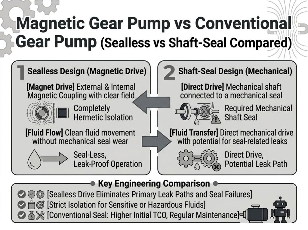
A magnetic gear pump and a conventional gear pump are the same positive-displacement machine — two meshing gears that trap and carry a fixed volume per revolution. The only real difference is how torque crosses the pressure boundary. A conventional gear pump drives the gears through a motor shaft that penetrates the housing, so it needs a dynamic mechanical seal (or packing) that leaks and wears.
A magnetic gear pump replaces that shaft with a magnetic coupling: an outer magnet on the motor drags an inner magnet on the gear shaft through a static containment shell — no penetration, no seal, zero leakage. The trade-off is cost and a small 5–8% eddy-current efficiency penalty on metallic shells. For compact, low-flow, low-power OEM equipment that cannot tolerate leaks or seal maintenance, the magnetic gear pump is the dominant choice.
In this guide
- Quick Answer
- What Is the Real Difference?
- How a Conventional Gear Pump Works
- How a Magnetic Gear Pump Works
- Feature Comparison Table
- Efficiency, Temperature & Torque: The Real Trade-offs
- Where Each Wins: Applications & OEM Equipment
- How to Choose (7 Steps)
- Common Engineering Mistakes
- Troubleshooting: Problem → Cause → Solution
- FAQ
- Why Choose GreenSky?
- References
What Is the Real Difference?
Strip away the marketing and both devices look nearly identical: a close-clearance housing, a pair of external or internal meshing gears, and flow that tracks speed as Q = D × N × ηv. The divergence is entirely in the drive interface:
- Conventional gear pump — motor shaft → coupling → gear shaft, passing through the housing wall. The shaft must be sealed against the fluid, which introduces a dynamic seal, a wear item, and a leak path.
- Magnetic gear pump — motor shaft → outer magnet → magnetic field → inner magnet → gear shaft. The field crosses a thin non-magnetic containment shell, so nothing rotating penetrates the wetted cavity. The seal becomes a static O-ring or weld.
That single interface decision drives almost every downstream difference — leakage risk, maintenance, efficiency, cost, and where each pump belongs. Both gear-pump types sit under the same standards umbrella: API 676 (4th ed., 2022) covers rotary positive-displacement pumps, while sealless designs are additionally governed by API 685 (3rd ed., 2022) for the containment and leak-detection requirements. For the motor side, both rely on IEC 60034 duty/thermal ratings and NEMA MG 1 efficiency tables.
How a Conventional Gear Pump Works
- Suction. As teeth disengage on the inlet, the expanding cavity drops pressure and draws fluid in.
- Transport. Fluid is trapped in pockets between the teeth and bore and carried around the periphery.
- Discharge. Teeth re-mesh at the outlet, collapsing the cavity and forcing fluid into the line.
- The seal. The motor shaft enters the housing through a mechanical seal (rotating + stationary faces, plus an elastomer secondary seal) or gland packing. This seal is the classic failure point.
How a Magnetic Gear Pump Works
- Micromotor spins the outer magnet. A BLDC (or AC) motor turns the outer drive magnet assembly.
- Field crosses the shell. The rotating field passes through the stationary, non-magnetic containment shell (the single part that defines a sealless pump).
- Inner magnet follows in lockstep. The inner magnet — rigidly fixed to the drive gear — is dragged around at identical speed with zero slip (synchronous coupling).
- Gears pump. The gear set moves fluid exactly as a conventional gear pump does.
- No leak path. With no shaft penetration, the only seals are static; the coupling also acts as an overload clutch that decouples (
T ∝ 1/g²pull-out) if the gears jam.
The complete gear-pump + coupling mechanics are detailed in our magnetic gear pump explainer, and the miniature end of the range in how a micro magnetic pump works.
Feature Comparison Table
| Attribute | Magnetic gear pump | Conventional gear pump |
|---|---|---|
| Drive interface | Magnetic coupling, sealless | Motor shaft + mechanical seal |
| Leak path | None (static shell only) | Rotating shaft seal (wear item) |
| Leakage risk | Zero in normal operation | Gradual weep → catastrophic |
| Seal maintenance | None | Periodic inspection / replacement |
| Service life | 20,000+ h (no seal) | Seal 2,000–5,000 h; pump longer |
| Efficiency | ~80–85% (metal shell; 5–8% eddy loss) | 80–95% |
| Dry-run tolerance | Poor — bearings fail in seconds | Better — brief dry run tolerable |
| Solids / abrasive | Sensitive (>20–100 µm laps shell) | More tolerant; wears gears/seal |
| High viscosity | Limited — magnetic slip + eddy heat | Excellent — thick oils, resins |
| Pressure capability | High (20–40 bar typical gear designs) | Very high (some >100 bar) |
| Temperature | Magnet-limited (NdFeB ~80–150 °C; SmCo >300 °C) | Seal-elastomer limited |
| Initial cost | Higher (magnet + shell) | Lower |
| Containment | Hermetic — toxic / pure / volatile fluids | Acceptable-leak for benign fluids |
| Compact / OEM fit | Excellent — small, low-power, leak-free | Good, but seal is a service point |
Efficiency, Temperature & Torque: The Real Trade-offs
Eddy-current loss — the magnetic pump’s one efficiency tax
The same rotating field that transmits torque also induces eddy currents in a conductive containment shell, wasting power as heat. On a metallic shell the loss is roughly 5–8% at typical duty, climbing with shell diameter, speed and wall thickness (1–5 kW on large couplings; up to 20 kW reported at high power). The fix is material, not size:
- Non-metallic shells (ceramic, PEEK, FRP) carry no eddy current — the loss vanishes, which is why compact, high-efficiency and low-power OEM pumps favor them.
- Metallic shells (Hastelloy C, 316 SS) keep high pressure/temperature but pay the 5–8% tax; advanced hybrid shells cut eddy loss by up to 90% while holding ~300 °C / 500 bar.
Magnet and seal temperature limits
Conventional gear pumps are limited by the seal elastomer (often NBR/EPDM, degrading sharply above ~100–150 °C). Magnetic gear pumps are limited by the magnet grade: NdFeB weakens around 80–150 °C, SmCo stays stable above 300 °C, and non-metallic shells cap near 120–150 °C while metal shells reach ~260 °C.
Torque and power
Both types share the hydraulic torque relationship:
Thyd = Δp × Vd / (2π × ηm) and Phyd = Δp × Q / 600
The magnetic pump adds one sizing rule the conventional pump doesn’t need: the coupling pull-out torque (scaling with 1/g²) must exceed the worst-case gear load by 1.2–1.5×, or the magnets slip apart under startup viscous torque. For drive selection, pair the pump with an IE4-class BLDC micromotor sized ≥1.15× shaft power — see our torque calculation guide and BLDC vs servo breakdown.
Where Each Wins: Applications & OEM Equipment
Choose a magnetic gear pump when…
- Fluid is hazardous, toxic, expensive, volatile or high-purity — strong acids, solvents, pharmaceuticals, reagents, fuels, inks. Zero leakage is a safety/compliance requirement, not a preference.
- A leak or seal stop is unacceptable — continuous metering, diagnostic instruments, fuel cells, electronics liquid-cooling loops.
- You need compact, low-flow, low-power OEM integration. In miniature fluid systems the shaft seal is proportionally the most failure-prone part; the sealless head plus a small BLDC drive is why OEM micro-pump makers (e.g. Micropump) lead with magnetic gear heads — flow from ~0.4 µL to 42 L/min, pressure to 80 bar, under 0.5 kg.
Choose a conventional gear pump when…
- The fluid is benign and lubricating — clean oil, fuel, water — where a small leak is acceptable.
- You need peak efficiency on high-viscosity fluids (resins, adhesives, syrups) or very high pressure, and magnetic slip / eddy heat would bite.
- Dry-running or mild solids are expected and the seal-maintenance overhead is an accepted trade-off for lower upfront cost.
How to Choose (7 Steps)
- Classify the fluid. Hazardous / pure / volatile → magnetic. Benign / lubricating → either, conventional is cheaper.
- Define the duty. Flow (
Q = D × N × ηv), discharge pressure, duty cycle (S1 vs S3 per IEC 60034-1), and ambient. - Decide the leak policy. Zero-leakage requirement → magnetic; small leak acceptable → conventional.
- Check efficiency budget. If eddy loss matters, pick a non-metallic shell (magnetic) or stay conventional for high-viscosity throughput.
- Verify temperature. Seal elastomer vs magnet grade (NdFeB → SmCo above ~150 °C) and shell material.
- Size the drive. Hydraulic power + losses, motor ≥1.15×; for magnetic, confirm coupling pull-out ≥1.2–1.5× load and BLDC efficiency (IE4).
- Confirm compliance. API 676/685, CE, RoHS/REACH for export; IEC 60601-1 / ISO 13485 for medical/analytical targets (see CE for European OEMs).
Common Engineering Mistakes
- Picking a magnetic pump then running it dry. The self-lubricating bearings die in seconds — always add a dry-run interlock or flow switch.
- Ignoring the eddy-current tax on a metal shell. You inherit 5–8% loss and heat; a non-metallic shell often reclaims it at low power.
- Forgetting coupling pull-out torque. Below 1.2–1.5× load the magnets slip and the pump stalls on startup viscous torque.
- Using a conventional gear pump on toxic fluid “to save money.” Seal leakage and its downtime cost (5–10× the seal) erase the savings.
- Choosing magnetic drive for a gritty slurry. Particles lap the shell and magnet; a conventional pump (or a strainer + magnetic pump) is the right call.
- Sizing the micromotor at 3× instead of ~1.15×. Oversizing wastes board space and battery in compact OEM designs.
- Specifying motor and pump separately. For OEM integration, co-spec the BLDC winding, voltage, and controller with the pump head — see OEM motor manufacturing.
Troubleshooting: Problem → Cause → Solution
| Problem | Likely cause | Solution |
|---|---|---|
| Gradual drip at shaft | Conventional seal wear / face damage | Replace seal; check alignment & flush plan |
| No flow on start (magnetic) | Coupling decoupled — load > pull-out | Prime; verify torque margin ≥1.2–1.5×; check gears |
| Efficiency below spec (magnetic) | Metal-shell eddy loss | Switch to non-metallic / hybrid shell |
| Magnet weakening / overheating | Shell eddy heat or ambient > magnet limit | Non-metallic shell; step up to SmCo; improve cooling |
| Bearing failure in seconds (magnetic) | Dry running or abrasive particles | Add dry-run protection + suction strainer |
| Contamination of fluid | Seal weep (conventional) or wrong wetted material | Upgrade to SS316 / PEEK / PTFE; go sealless |
FAQ
What is the main difference between a magnetic gear pump and a conventional gear pump?
Both are positive-displacement gear pumps with identical pumping action. The only structural difference is how motor torque crosses the pressure boundary. A conventional gear pump passes a motor shaft through the housing, needing a dynamic mechanical seal that leaks and wears. A magnetic gear pump replaces that shaft with a magnetic coupling — an outer magnet on the motor and an inner magnet on the gear shaft, separated by a static containment shell — so there is no rotating penetration and no seal to leak.
Which gear pump leaks less, magnetic or conventional?
The magnetic gear pump. It has no dynamic shaft seal; the only seals are static O-rings or welds at the shell, so it is inherently leak-free. A conventional gear pump always has a rotating shaft seal that wears — mechanical seals account for roughly 70% of pump maintenance cost, with typical seal life of 2,000–5,000 hours versus 20,000+ hours for a magnetic drive gear pump.
Is a magnetic gear pump less efficient than a conventional gear pump?
Usually yes, by a small margin. A metallic containment shell induces eddy currents from the rotating field, costing roughly 5–8% efficiency (more at high speed or power — up to 1–5 kW on large couplings). A conventional gear pump has no such loss and runs 80–95% efficient. You can recover most of the gap with a non-metallic shell (ceramic/PEEK/FRP), which is why compact, low-power OEM pumps favor non-metallic shells.
Can a magnetic gear pump run dry or handle abrasive fluids?
Poorly on both. Its product-lubricated bearings are cooled by the pumped fluid, so dry running destroys them in seconds; abrasive particles lap the inner magnet and shell. A conventional gear pump tolerates brief dry running and mild solids better, though gears and seal still wear. For clean, corrosive, toxic, volatile or high-purity liquids, the magnetic gear pump is safer.
Why do magnetic gear pumps dominate compact, low-flow OEM equipment?
In a miniaturized device the shaft seal is proportionally the most failure-prone, hardest-to-service part, and a leak or maintenance stop is unacceptable — the sealless coupling removes it. Low-flow metering also needs a leak-free, contamination-free path, and the small BLDC micromotor with no seal drag keeps power low so the whole head fits in a few centimetres.
How do I decide between a magnetic and a conventional gear pump?
Choose magnetic when the fluid is hazardous, toxic, expensive, volatile or high-purity, when a leak or seal maintenance is unacceptable, or when you need compact, low-flow, low-power OEM integration. Choose conventional when the fluid is benign and lubricating, when you need the highest efficiency at high viscosity or very high pressure, or when dry-running and mild solids are expected and a small leak is acceptable for lower cost.
Why Choose GreenSky?
GreenSky Power — the drive behind your gear pump, magnetic or conventional
Whichever interface you choose, the gear pump is only as good as the micromotor and controller turning it. GreenSky Power is a B2B motor manufacturer supplying the compact BLDC / PMSM drive motors and integrated drive electronics for both sealless and shaft-sealed gear pumps:
- Compact, low-power drives — 12–42 mm BLDC motors with custom windings for 3.7–48 VDC, tuned for low current draw and long battery life in OEM devices.
- High efficiency — IE4-class permanent-magnet designs with FOC controllers for precise flow-by-RPM, recovering the efficiency gap on any pump.
- OEM-ready integration — optional encoder, 0–10 V / PWM setpoint, tachometer output, and integrated speed controller in the motor can.
- Export compliance — RoHS, REACH and CE-ready documentation, with IEC 60601-1 / ISO 13485-aligned support for medical and analytical targets (see our European OEM program).
- Co-design — from custom drive solutions to volume OEM manufacturing, we spec the motor and controller together with your pump head.
Explore our motor portfolio and efficiency / battery-runtime guidance to match a drive to your gear pump.
References
- IEC 60034-1:2019, Rotating electrical machines — Part 1: Rating and performance (duty cycles S1–S10, thermal classes). webstore.iec.ch/publication/60135
- IEC 60034-30-1:2014, Rotating electrical machines — Part 30-1: Efficiency classes IE1–IE5. webstore.iec.ch/publication/65564
- NEMA MG 1-2021, Motors and Generators (U.S. motor efficiency tables). nema.org/standards/view/mg-1-motors-and-generators
- U.S. DOE, 10 CFR Part 431 — Energy Efficiency Program for Certain Commercial and Industrial Equipment (motors Subpart B; clean-water pumps Subpart Y, PEI metric). ecfr.gov/current/title-10/part-431
- API Standard 685, Sealless Centrifugal Pumps for Petroleum, Petrochemical, and Gas Industry Process Service, 3rd ed. (2022). api.org/products-and-services/standards
- A. Hatch, A. E. Kamholz, G. Holman, P. Yager, K. F. Böhringer, “A Ferrofluidic Magnetic Micropump,” IEEE/ASME J. Microelectromech. Syst., 10(2):215–221, 2001. doi.org/10.1109/84.925748
- M. Khoo and C. Liu, “A novel micromachined magnetic membrane microfluid pump,” IEEE EMBS, 2000. doi.org/10.1109/IEMBS.2000.900628
- IEA, Energy Efficiency of Electric Motor Systems (motor-driven systems and the IE4/IE5 pathway). iea.org/reports/energy-efficiency-of-electric-motor-systems
- SKF, Bearings in pumps — selection and lubrication for long life (product-lubricated bearing guidance). skf.com/group/industries/pumps
- Siemens, SINAMICS drives for pump and fan applications (compact VFD / motor control). siemens.com/global/en/products/drives/motor-control/drives/sinamics.html
