Gear Motor vs DC Motor: What’s the Difference and Which Should You Choose?
Quick Answer:
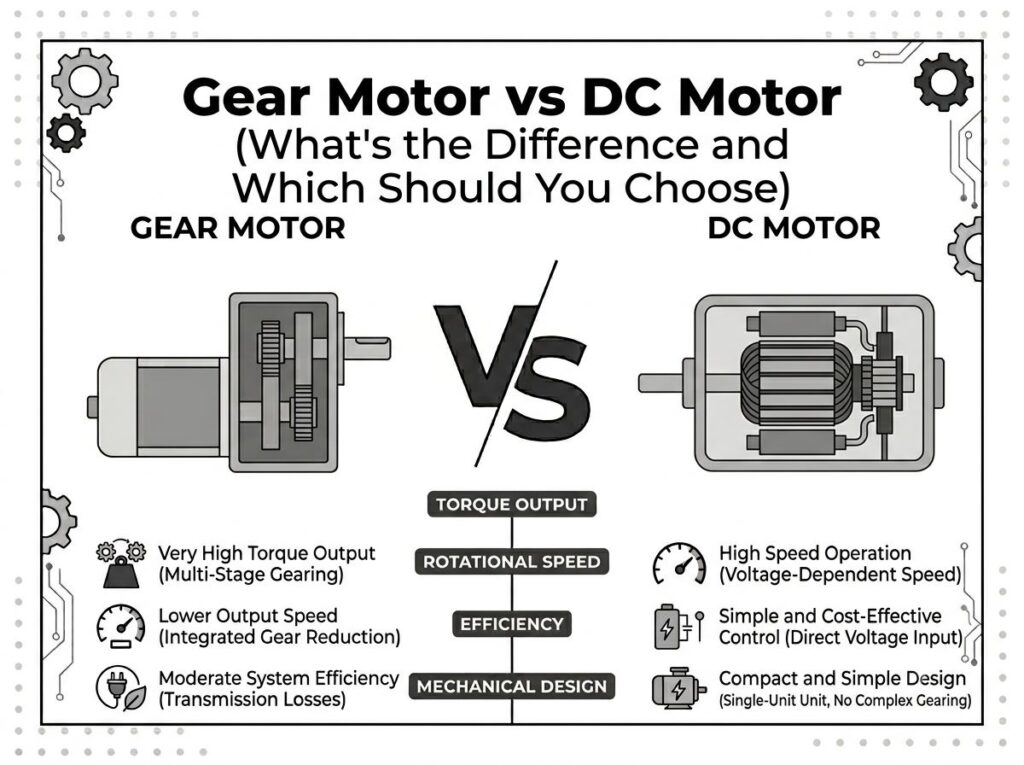
A gear motor is a DC or AC motor combined with a gearbox, while a DC motor refers only to the electric motor itself. Gear motors provide significantly higher torque and lower output speed by using mechanical gear reduction, making them ideal for conveyors, robotics, automation equipment, and motion control systems. In contrast, DC motors typically deliver higher rotational speed and are commonly used in direct-drive applications such as pumps, fans, and cutting blades.
Many industrial gear motors today actually use permanent magnet DC motors or brushless DC motors paired with planetary, spur, worm, or helical gearboxes to achieve the desired balance between speed, torque, efficiency, and positioning precision.
What Is a DC Motor?
A DC (Direct Current) motor is an electric motor powered by direct current. It converts electrical energy into rotational mechanical energy through electromagnetic interaction between the stator and rotor.
Because of their simple construction, fast response, compact size, and relatively easy speed control, DC motors have been widely used for decades in industrial automation, medical devices, household appliances, electric vehicles, robotics, power tools, and battery-powered equipment.
Unlike gear motors, a standard DC motor does not inherently reduce speed or increase torque. Instead, it delivers its output directly from the motor shaft. If lower speed or higher torque is required, a gearbox can be added externally to create a DC gear motor.
Basic Construction of a DC Motor
Although different DC motor technologies exist, most share several fundamental components:
- Rotor (Armature) — the rotating component that generates mechanical output.
- Stator — produces the stationary magnetic field surrounding the rotor.
- Permanent Magnets or Field Windings — create magnetic flux required for torque generation.
- Bearings — support the rotating shaft while minimizing friction.
- Output Shaft — transfers rotational power to the driven equipment.
The interaction between the magnetic fields of the rotor and stator generates electromagnetic torque, causing the rotor to rotate continuously.
Types of DC Motors
Modern industrial systems generally use two primary categories of DC motors.
1. Brushed DC Motor
Brushed DC motors use carbon brushes and a mechanical commutator to switch current through the rotor windings during rotation.
Their advantages include:
- Simple controller requirements
- Low initial cost
- Easy installation
- Excellent starting torque
- Widely available worldwide
However, brushes gradually wear over time, requiring periodic maintenance. Mechanical commutation also produces electrical noise, sparks, and friction, limiting lifespan in demanding industrial environments.
Typical Applications
- Power tools
- Automotive accessories
- Household appliances
- Small actuators
- Portable equipment
2. Brushless DC Motor (BLDC)
Brushless DC motors eliminate mechanical brushes entirely. Instead, electronic controllers perform commutation based on rotor position detected by Hall sensors or encoder feedback.
Compared with brushed motors, BLDC motors offer numerous engineering advantages:
- Higher efficiency
- Longer service life
- Lower maintenance
- Higher power density
- Excellent speed regulation
- Lower operating noise
- Better thermal performance
Because there are no brushes generating friction or wear, BLDC motors are increasingly replacing traditional brushed motors in industrial automation and intelligent equipment.
Common BLDC Applications
- Industrial robots
- AGVs
- Autonomous mobile robots (AMRs)
- Electric lawn mowers
- Medical equipment
- Servo systems
- Smart logistics equipment
Permanent Magnet Technology
Most modern DC motors use permanent magnets rather than wound field coils to generate the stator magnetic field.
Permanent magnet DC motors provide several important engineering benefits:
- Higher efficiency
- Lower electrical losses
- Compact dimensions
- Reduced weight
- Improved torque density
- Lower energy consumption
High-performance rare-earth magnets, particularly Neodymium Iron Boron (NdFeB), have significantly improved the performance of modern DC motors over the past decade, enabling compact motors to deliver much higher torque than previous generations.
How a DC Motor Produces Torque
The operating principle of a DC motor is based on electromagnetic force.
When electrical current flows through the motor windings, a magnetic field is generated. The interaction between this magnetic field and the magnetic field produced by the stator creates rotational force on the rotor.
As the magnetic poles continuously switch position through either mechanical commutation (brushed motors) or electronic commutation (BLDC motors), the rotor continues rotating and delivers mechanical power to the output shaft.
The motor’s performance is primarily influenced by:
- Supply voltage
- Current
- Motor winding design
- Magnet strength
- Controller performance
- Cooling capability
Advantages of DC Motors
| Advantage | Engineering Benefit |
|---|---|
| High Speed | Suitable for direct-drive applications |
| Compact Size | Easy integration into equipment |
| Simple Speed Control | Voltage or PWM regulation |
| Fast Dynamic Response | Quick acceleration and deceleration |
| Wide Speed Range | Typically 500–10,000 RPM |
| High Efficiency (BLDC) | Lower energy consumption |
Limitations of Standard DC Motors
Despite their many advantages, standard DC motors are not ideal for every application.
Because they rotate at relatively high speed while producing limited output torque, they often cannot directly drive heavy mechanical loads.
Typical limitations include:
- Lower output torque without reduction gears
- Reduced holding capability
- Poor low-speed stability under heavy load
- Additional gearbox required for many industrial systems
For this reason, engineers frequently combine DC motors with gearboxes to obtain higher torque, lower speed, and improved motion control. The result is known as a DC gear motor, which will be explained in the next section.
What Is a Gear Motor?
A gear motor is an integrated drive unit consisting of an electric motor and a mechanical gearbox. Unlike a standard DC motor that delivers power directly from its output shaft, a gear motor reduces rotational speed through a gear train while proportionally increasing output torque.
It is important to understand that a gear motor is not a separate motor technology. Instead, it is an assembly that combines two major components:
- Electric Motor – Generates rotational power.
- Gearbox (Speed Reducer) – Converts high-speed, low-torque output into low-speed, high-torque output.
Depending on the application, the motor can be a brushed DC motor, brushless DC (BLDC) motor, AC induction motor, servo motor, or stepper motor. The gearbox is selected according to the required reduction ratio, efficiency, noise level, and output torque.
Basic Structure of a Gear Motor
A typical industrial gear motor consists of the following components:
| Component | Function |
|---|---|
| Electric Motor | Produces rotational power |
| Input Shaft | Transfers power from the motor into the gearbox |
| Gear Train | Reduces speed and multiplies torque |
| Bearings | Support rotating shafts and reduce friction |
| Gear Housing | Protects internal gears and retains lubricant |
| Output Shaft | Delivers torque to the driven equipment |
Because the motor and gearbox are designed as a matched system, gear motors generally provide higher reliability, lower installation complexity, and better mechanical alignment than separately assembled motor-gearbox combinations.
How Does a Gearbox Increase Torque?
A gearbox works according to the principle of mechanical speed reduction.
When the motor drives a smaller gear that meshes with a larger gear, the rotational speed decreases while the available torque increases. This allows relatively small motors to move heavy loads efficiently.
Engineering relationship:
Gear Ratio ↑
↓
Output Speed ↓
↓
Output Torque ↑
For example, a DC motor operating at 3,000 RPM with an output torque of 0.4 N·m can be paired with a 30:1 gearbox. Ignoring minor transmission losses, the output speed becomes approximately 100 RPM while the output torque increases to around 12 N·m.
This simple principle explains why gear motors are widely used in applications that require high starting torque, controlled motion, or the ability to move heavy loads.
Common Types of Gear Motors
Different gearbox designs provide different advantages. Selecting the appropriate gearbox depends on torque requirements, installation space, efficiency, noise level, and budget.
1. Spur Gear Motor
Spur gear motors use straight-cut gears mounted on parallel shafts. They are among the simplest and most economical gear motor designs.
Advantages:
- Simple construction
- Low manufacturing cost
- High mechanical reliability
- Easy maintenance
- Suitable for moderate torque applications
Typical Applications:
- Packaging machinery
- Automatic doors
- Office equipment
- Material handling systems
2. Planetary Gear Motor
Planetary gear motors are widely recognized as the preferred solution for precision motion control. Their gearbox consists of a central sun gear, multiple planet gears, and an internal ring gear.
Because several planet gears share the transmitted load simultaneously, planetary gearboxes achieve exceptionally high torque density while maintaining compact dimensions.
Advantages:
- High torque capacity
- Compact size
- Excellent load distribution
- High transmission efficiency
- Low backlash options
- Smooth operation
Typical Applications:
- Industrial robots
- AGVs and AMRs
- Servo systems
- Medical devices
- Electric wheel drives
- Smart automation equipment
Modern robotic systems frequently use BLDC planetary gear motors because they combine the efficiency of brushless technology with the high torque output of planetary reduction.
3. Worm Gear Motor
Worm gear motors use a worm shaft that meshes with a worm wheel positioned at a right angle. This configuration enables large reduction ratios within a compact package.
One of the most valuable characteristics of worm gear motors is their ability to provide partial or complete self-locking, preventing reverse motion under load in many applications.
Advantages:
- Very high reduction ratios
- Compact right-angle output
- Quiet operation
- Good shock absorption
- Self-locking capability in many designs
Typical Applications:
- Lifting mechanisms
- Gate operators
- Turnstiles
- Conveyor positioning systems
- Industrial actuators
4. Helical Gear Motor
Helical gear motors use angled gear teeth that engage gradually rather than simultaneously. This design significantly reduces vibration and operating noise while improving load-carrying capacity.
Advantages:
- Very high efficiency
- Smooth and quiet operation
- High load capacity
- Long service life
- Suitable for continuous-duty operation
Typical Applications:
- Heavy-duty conveyors
- Mining equipment
- Industrial production lines
- Food processing machinery
- Large automation systems
Advantages of Gear Motors
| Advantage | Engineering Benefit |
|---|---|
| High Output Torque | Moves heavy loads efficiently |
| Low Output Speed | Improves motion control and positioning |
| Compact Integrated Design | Simplifies installation |
| Improved Load Capacity | Suitable for industrial machinery |
| Wide Reduction Ratios | Flexible speed selection |
| High Reliability | Long operating life under continuous duty |
Typical Industrial Applications of Gear Motors
Gear motors are selected whenever applications require controlled movement rather than maximum rotational speed.
Common examples include:
- Conveyor systems
- Industrial robots
- Automated Guided Vehicles (AGVs)
- Autonomous Mobile Robots (AMRs)
- Warehouse automation
- Electric wheel drives
- Swing gates
- Turnstiles
- Automatic doors
- Lawn mower drive wheels
- Material handling equipment
- Packaging machinery
Although many of these systems are commonly referred to simply as “gear motors,” the motor inside is frequently a high-efficiency permanent magnet DC motor or BLDC motor. The gearbox is what transforms that motor into a low-speed, high-torque drive solution.
Can a DC Motor Be a Gear Motor?
Yes. In fact, many industrial gear motors are built by combining a DC motor with a gearbox. This is one of the most common drive configurations used in modern automation equipment.
DC Motor
+
Gearbox
=
DC Gear Motor
This simple combination allows engineers to take advantage of the high rotational speed and compact size of a DC motor while obtaining the low-speed, high-torque output required by most industrial machinery.
Why Not Use a DC Motor Alone?
A standard DC motor often rotates at speeds ranging from 500 to 10,000 RPM, depending on its design and operating voltage. While this is ideal for direct-drive applications such as fans or pumps, it is usually too fast for equipment that requires controlled motion or high pulling force.
For example, a conveyor belt typically operates at only a few dozen revolutions per minute. If driven directly by a high-speed DC motor, the conveyor would run far too quickly and produce insufficient torque to move heavy products.
Adding a gearbox solves this problem by reducing speed and multiplying torque, allowing a relatively small motor to handle much larger loads.
Common DC Gear Motor Configurations
| Motor Type | Gearbox Type | Typical Application |
|---|---|---|
| Brushed DC Motor | Spur Gearbox | Office equipment, small machinery |
| Brushed DC Motor | Worm Gearbox | Gate operators, actuators |
| BLDC Motor | Planetary Gearbox | Robotics, AGVs, AMRs |
| BLDC Motor | Helical Gearbox | Industrial automation |
| Permanent Magnet DC Motor | Planetary Gearbox | Medical equipment, wheel drives |
Today, the majority of high-performance industrial motion systems no longer treat the choice as gear motor versus DC motor. Instead, they integrate both technologies to create a drive solution that delivers the optimal balance of speed, torque, efficiency, precision, and durability.
Gear Motor vs DC Motor: Key Differences
Understanding the fundamental differences between a gear motor and a DC motor is essential for selecting the correct drive system in industrial design. Although both are used to produce rotational motion, they differ significantly in structure, output characteristics, and application suitability.
A DC motor is a standalone electromagnetic device that produces high-speed rotational output. A gear motor, on the other hand, is a complete mechanical system that combines a motor with a gearbox to reduce speed and increase torque.
In practical engineering terms, the difference is not just structural—it directly affects torque density, speed range, efficiency behavior under load, and system integration complexity.
| Feature | DC Motor | Gear Motor |
|---|---|---|
| Definition | Electric motor only | Motor + gearbox assembly |
| Speed | High (direct output) | Low (after reduction) |
| Torque | Lower at shaft | Higher due to gear ratio |
| Efficiency | High electrical efficiency | Depends on gearbox type |
| Cost | Lower system cost | Higher system cost (additional gearbox) |
| Precision Control | Medium (depends on controller) | High (mechanical reduction improves stability) |
| Typical Applications | Fans, pumps, blowers | Conveyors, robotics, automation systems |
Torque Comparison
Torque is one of the most critical deciding factors when choosing between a DC motor and a gear motor. While DC motors can generate sufficient torque for lightweight or high-speed applications, they often fall short in heavy-load or low-speed conditions.
Gear motors solve this limitation by using mechanical reduction through a gearbox, effectively multiplying output torque without increasing motor size.
How Gear Ratio Affects Torque
The relationship between gear ratio, speed, and torque is fundamental in mechanical engineering:
Gear Ratio ↑
↓
Output Speed ↓
↓
Output Torque ↑
This means that when a motor is paired with a gearbox, the system trades speed for torque. For example, a 10:1 gearbox reduces speed by a factor of ten while increasing torque by approximately the same factor (minus efficiency losses).
In real-world applications, this allows a small DC motor to perform tasks that would otherwise require a much larger motor if used without a gearbox.
Engineering Example
Consider a DC motor with the following specifications:
- Speed: 3000 RPM
- Torque: 0.5 N·m
When paired with a 20:1 planetary gearbox:
- Output Speed: ~150 RPM
- Output Torque: ~10 N·m (minus gearbox losses)
This demonstrates why gear motors are preferred in applications requiring high starting torque such as conveyors, robotics joints, and automated lifting systems.
Speed Comparison
Speed is another major differentiator between DC motors and gear motors. DC motors are naturally high-speed devices, while gear motors are designed to operate at reduced speeds optimized for mechanical loads.
Typical Speed Ranges
- DC Motor: 500–10,000 RPM
- Gear Motor Output: 5–500 RPM
The large reduction in speed is not a disadvantage but a functional requirement for most industrial systems. Many mechanical loads cannot operate efficiently at high speed and require controlled motion instead.
For example:
- Robotic arms require precise, low-speed movement
- Conveyors must maintain stable speed under variable loads
- Turnstiles require smooth acceleration and deceleration
In these cases, a gear motor provides significantly better control compared to a direct-drive DC motor.
Efficiency Comparison
A common misconception is that gear motors are always inefficient due to energy losses in the gearbox. In reality, modern gearbox technologies—especially planetary and helical designs—offer very high mechanical efficiency.
Efficiency depends heavily on gear type, lubrication quality, load conditions, and manufacturing precision.
Gearbox Efficiency by Type
| Gearbox Type | Typical Efficiency Range | Engineering Notes |
|---|---|---|
| Planetary Gearbox | 95% – 98% | High efficiency, compact design, widely used in robotics and AGVs |
| Helical Gearbox | 96% – 98% | Smooth transmission, low noise, high load capacity |
| Spur Gearbox | 90% – 95% | Simple design, moderate efficiency, cost-effective |
| Worm Gearbox | 50% – 90% | High reduction ratio but significant sliding friction losses |
While DC motors are highly efficient in electrical energy conversion (especially BLDC types), gear motors introduce mechanical losses. However, in properly selected applications, the improved torque and reduced system stress often outweigh the efficiency penalty.
In robotics and automation, planetary gear systems are widely used because they provide an optimal balance between efficiency, torque density, and compact size.
Cost Comparison
Cost is a major factor in industrial procurement decisions. However, it is important to distinguish between component cost and system-level cost.
A DC motor alone is generally less expensive than a complete gear motor system. However, when a gearbox, mounting structure, and mechanical coupling are required, the total system cost may increase significantly.
| Cost Element | DC Motor System | Gear Motor System |
|---|---|---|
| Motor Cost | Lower | Medium |
| Gearbox Cost | Not required | Required |
| Controller Cost | Required (especially BLDC) | Required (depending on motor type) |
| Mechanical Integration | Higher engineering effort | Pre-integrated system |
| Total System Cost | Lower for simple applications | Higher but more optimized for torque-critical systems |
In many OEM projects, gear motors reduce overall engineering cost even if component cost is higher, because they simplify mechanical design, reduce assembly time, and improve system reliability.
Which Is Better for Robotics?
Robotics is one of the most important application fields when comparing gear motors and DC motors. The key requirements in robotics include precise positioning, high torque at low speed, compact structure, and smooth motion control.
A standard DC motor alone is rarely sufficient for robotic joints or load-bearing movement because it operates at high speed with relatively low torque at the shaft. Without a reduction system, it cannot maintain stable motion under varying loads.
For this reason, most modern robotics systems use a combination of a DC or BLDC motor with a planetary gearbox, forming a DC planetary gear motor or BLDC gear motor.
Best solution: DC/BLDC planetary gear motor
Which Is Better for Conveyor Systems?
Conveyor systems require continuous operation, stable speed, and sufficient torque to move materials under varying load conditions.
A gear motor is typically the better choice because it provides consistent low-speed output and high torque without requiring complex external mechanical design.
DC motors without gear reduction are not ideal because they rotate too fast and cannot efficiently handle heavy loads at low speed.
Best solution: Gear motor (especially helical or worm gear types depending on load conditions)
Which Is Better for Pumps?
Pumps generally require high-speed rotation rather than high torque. The fluid dynamics of pumping systems depend heavily on impeller speed, which makes direct-drive DC motors a more suitable choice.
In most pump applications, adding a gearbox would unnecessarily reduce efficiency and increase system complexity.
BLDC motors are especially popular in modern pump systems due to their high efficiency, compact size, and ability to maintain stable speed under varying load conditions.
Best solution: DC motor or BLDC motor (direct drive)
Which Is Better for Lawn Mowers?
Lawn mower systems typically require two different motion requirements: blade rotation and wheel drive. These two subsystems have very different mechanical needs.
Blade System
The cutting blade requires high-speed rotation for effective cutting performance. In this case, a direct-drive DC or BLDC motor is preferred.
Adding a gearbox would reduce blade speed and negatively impact cutting efficiency.
Best solution: Direct-drive BLDC motor
Drive Wheel System
The wheel drive system requires high torque at low speed, especially when climbing slopes or moving over uneven terrain.
A gear motor is ideal here because it provides the necessary torque multiplication and stable low-speed control.
Best solution: DC gear motor or BLDC planetary gear motor
Which Is Better for Turnstiles?
Turnstile systems require controlled rotation, smooth acceleration, and reliable torque output to ensure safety and consistent operation in public access systems.
A planetary gear motor is the most widely used solution in modern turnstile designs because it provides:
- High torque density
- Compact installation size
- Precise position control
- High durability for continuous operation
Worm gear motors are also used in some designs due to their self-locking capability, but planetary systems offer better efficiency and smoother motion control.
Best solution: Planetary gear motor (DC or BLDC based system)
How to Choose Between Gear Motors and DC Motors
Selecting between a gear motor and a DC motor depends entirely on application requirements such as torque demand, speed range, duty cycle, space constraints, and control precision.
The following application matrix provides a simplified engineering guideline:
| Application | Recommended Solution |
|---|---|
| Fan | DC Motor |
| Pump | DC Motor / BLDC Motor |
| Conveyor | Gear Motor (Helical / Spur) |
| AGV | BLDC Planetary Gear Motor |
| Robot Joint | BLDC Planetary Gear Motor |
| Lawn Mower Blade | BLDC Direct Drive Motor |
| Lawn Mower Drive Wheel | DC Gear Motor / BLDC Gear Motor |
| Turnstile | Planetary Gear Motor |
In modern industrial design, the decision is rarely “gear motor vs DC motor” alone. Instead, engineers increasingly combine both concepts by using a DC or BLDC motor integrated with a precision gearbox to achieve optimal system performance.
Why OEM Buyers Choose Greensky Power
For OEM manufacturers and industrial automation companies, selecting a reliable motor supplier is not only about product specification, but also about system integration capability, customization flexibility, and production stability.
Greensky Power provides integrated motion solutions designed for industrial applications requiring torque optimization, compact structure, and long service life.
- Planetary Gear Motors
- Spur Gear Motors
- Worm Gear Motors
- BLDC Gear Motors
- Custom Gearbox Engineering
- Motor + Gearbox Integrated Solutions
- OEM/ODM Design Support
- Low MOQ for Engineering Samples
- Fast Prototyping and Validation
These capabilities allow OEM customers to reduce development time, improve mechanical reliability, and accelerate product launch cycles in competitive industrial markets.
FAQ
Is a gear motor the same as a DC motor?
No. A DC motor is a standalone electric motor, while a gear motor is a motor combined with a gearbox to reduce speed and increase torque.
Can a DC motor have a gearbox?
Yes. When a gearbox is added to a DC motor, the result is called a DC gear motor, commonly used in industrial automation and robotics.
Is a gear motor stronger than a DC motor?
A gear motor provides higher output torque due to gear reduction, but it does not inherently generate more power. It trades speed for torque.
Why use a planetary gear motor?
Planetary gear motors offer high torque density, compact size, high efficiency, and excellent load distribution, making them ideal for robotics and AGVs.
Which motor is best for robotics?
Most robotics systems use BLDC motors combined with planetary gearboxes to achieve precise motion control and high torque output.
Which motor is best for conveyors?
Gear motors, especially helical or spur types, are commonly used because they provide stable low-speed high-torque operation.
References
1. IEEE Transactions on Industrial Electronics – Electric Motor Drive Systems
2. Electric Machinery Fundamentals – Stephen J. Chapman
3. Mechanical Engineering Design – Shigley’s Mechanical Engineering Design Principles
4. Industrial Gear Systems Handbook – Gear Technology Journal
5. Brushless DC Motor Applications in Automation Systems – Power Electronics Review