36V BLDC Motor Controller
Compact, efficient 36 V brushless DC motor controllers built for the battery-bus world of e-bikes, AGVs and light electric vehicles. 10–80 A continuous, 200–2,000 W, field-oriented control (FOC) or square wave, with CAN / RS485 to the pack’s BMS and regenerative braking — supplied to order for OEM customers.
A Controller Is the Drive, Not the Motor
The 36V BLDC motor controller is the power stage and the brain that turns a DC bus into the three-phase sequence a brushless motor needs. At 36 V it is rarely a stand-alone box on a lab bench — it is part of a battery-powered system, talking to the pack’s battery-management system (BMS) and recovering energy on the way down.
As an adjustable-speed drive, this controller sits inside IEC 61800-1’s definition of a DC power drive system: a semiconductor power converter plus the control, protection, monitoring and measurement that feeds the motor. Understanding it that way — rather than as an accessory — is what keeps the current, the BMS handshake and the protection features on the same page.
36V BLDC Controller Product Range
The current rating is the axis that matters. Three current bands cover small fans up to AGV drive wheels, with the control method and the customisation chosen separately.
36V 10–20 A
For small fans, pumps and compact battery systems, where the motor current is a few amps and the drive sits close to the battery.
36V 20–40 A
Ideal for e-bikes and light automation, the workhorse band for traction and positioning duty on a 36 V pack.
36V 40–80 A
For AGV and medium-power applications, where peak torque and low-speed holding current are what count.
Sensor / Sensorless
Flexible control depending on application — Hall sensors for low-speed stability, sensorless for a simpler harness.
FOC Controllers
High efficiency and smooth performance, with the current loop that gives quiet, low-ripple torque at low speed.
OEM Custom Controllers
Customized firmware, connectors and housing, so the drive matches your pack and panel rather than the other way round.
What 10–80 A Buys You at 36 V
Power is voltage times current, so the published 10–80 A band maps directly onto a 360–2,880 W window of bus power at 36 V. The chart reads the same relationship you would check on a motor — and it is the fastest way to see whether a controller is big enough before you buy it.
| Controller current | Bus power at 36 V | Typical duty |
|---|---|---|
| 10 A | 360 W | Small fans, pumps |
| 40 A | 1,440 W | E-bikes, light automation |
| 80 A | 2,880 W | AGV, medium power |
Current is the hard limit
An over-current trip is not a subtle warning — it is the drive protecting itself. Pick the controller by the motor’s peak current, not its rated wattage, because the peak is what trips the protection.
Power follows the bus
The 2,000 W top end needs a real 36 V supply. If the pack sags under load, the same motor draws more current for the same power — so the current rating is the safer number to design around.
The window you actually buy
200 W is the floor, not a precision point. Below a few amps the switching losses dominate, so very small loads are better served by a drive sized honestly rather than over-specified.
The published 10–80 A and 200–2,000 W are reproduced exactly. Bus power and current are related by the 36 V bus and nothing else; the nameplate and the drawing issued against your motor are the controlling documents. Peak current, derating and the exact trip points are confirmed on that drawing.
How to Choose a 36V BLDC Motor Controller
Six decisions fix the right controller, and the first one — current matching — is where most wrong purchases happen.
Current matching
Controller current should exceed motor current by 20–30%. The margin is for start-up, load spikes and ambient derating — not for wasted headroom.
Control mode
FOC for precision and quiet low-speed torque, square wave for cost-sensitive use where torque ripple does not matter.
Sensor type
Hall sensors for stable low-speed and position, sensorless for a simpler harness and lower part count — but sensorless needs a minimum speed to lock on.
Battery interface
On a 36 V pack the drive usually talks to the BMS over CAN or RS485 — SOC, enable and the regen handshake are negotiated, not just a PWM throttle.
Protection features
Over-current, over-voltage and thermal protection are not optional extras — they are the difference between a drive that fails safely and one that fails destructively.
Application matching
Different tuning for e-bike, fan and pump. An e-bike profile needs regen and a soft reverse; a fan ramps gently; a pump holds a set point.
The 20–30% current margin is a rule of thumb for steady-state matching, not a substitute for the drive’s own derating curves. Confirm the peak current, the trip points and the ambient derating against the motor and the 36 V pack you actually use.
Applications of 36V BLDC Controllers
E-Bikes & Scooters
The natural 36 V pack voltage, with regen and the BMS handshake that a road-legal-class e-bike or scooter expects.
AGV & Robotics
Hard low-speed torque and fast reversal for drive wheels, where FOC keeps the motion smooth.
HVAC Fan Systems
Soft ramps and speed control, with the efficiency that pays back over continuous duty.
Water Pumps
Constant-pressure and flow control, where the drive holds a set point rather than a speed.
Automation Equipment
Positioning and feed axes, where the drive’s current loop gives the repeatability the process needs.
Battery Powered Devices
Compact, efficient drives for cordless and mobile equipment, where every watt from the pack is budgeted.
For a pump or any fluid-handling application, the wetted seal and housing materials must be verified against the actual service environment — the controller’s job is the drive, but the machine still has to survive the fluid it moves.
Our Manufacturing Capabilities
Greensky supports OEM and ODM development for BLDC motor application manufacturers.
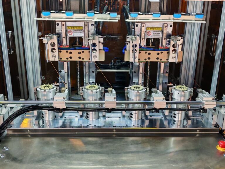
Motor Production Line
Advanced production lines ensure consistent quality and high production capacity for global BLDC motor application manufacturers.
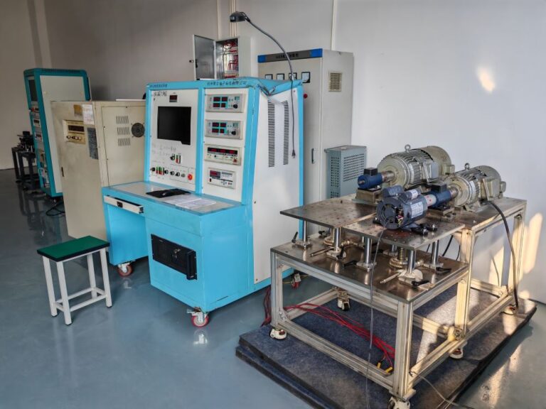
Motor Testing Laboratory
Professional testing equipment verifies torque, efficiency, durability and performance before shipment.
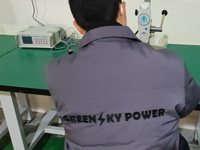
Quality Inspection
Strict inspection procedures ensure each motor meets international standards and customer specifications.

OEM Production
Flexible OEM manufacturing supports custom BLDC motor solutions for application manufacturers.
Controller Ratings and Interface
What is fixed across the 36 V range, what is set per order, and the documents available today.
| Parameter | Specification |
|---|---|
| Voltage | 36 V DC |
| Current range | 10 – 80 A |
| Power range | 200 W – 2,000 W |
| Control mode | FOC / Square Wave |
| Efficiency | ≥94% |
| Communication | PWM / CAN / RS485 |
| Protection | Over-current / Over-voltage / Thermal |
| Logic level and connector pinout | Not specified — confirm before design freeze |
There is no single datasheet covering every 36 V controller build, because the current band, control mode, connectors and firmware are configured per order. The documents above give the range and the wiring conventions; the drawing issued against your motor and drive is the controlling document. If a download does not start in a mobile in-app browser, open this page in the system browser and tap again.
Drive interface — confirm before design freeze
What to ask for · its current status · why it matters on a real machine| Item | Status | Why it is on this list |
|---|---|---|
| Bus voltage | 36 V DC nominal | Ten series Li-ion cells give 36 V as the natural pack voltage; the working range and tolerance against pack sag have to be confirmed for your battery. |
| Continuous and peak current | Not specified — confirm before design freeze | The 10–80 A is the range, not a rating. The continuous and the peak current for your motor, plus the peak duration, fix the actual drive you need. |
| Output power | 200 – 2,000 W (published) | The useful output at ≥94% efficiency; bus power is higher (up to ~2,880 W at 80 A) and the two numbers describe different limits. |
| Battery / BMS communication | PWM / CAN / RS485 per order; mapping to be defined | On a 36 V pack the drive usually negotiates SOC, enable and the regen handshake with the BMS. CAN and RS485 are buses — the message IDs, baud and register map have to be agreed. |
| Logic level and throttle | Not specified — confirm before design freeze | A 3.3 V host driving a 5 V input, or the reverse, is the most common integration failure. Get the level and the PWM frequency in writing before the control PCB is frozen. |
| Hall / sensor wiring and pinout | See the BLDC series datasheet | Phase and Hall order must match between drive and motor; reversing either will not run correctly, and the pinout has to match your harness. |
| Protection set points | Not specified — confirm before design freeze | Over-current, over-voltage and thermal trip points are configured, not universal. Set them to the motor and the application, not to a default. |
| Regenerative braking | Supported; recovery current to confirm | Regen recovers energy to the 36 V pack on e-bikes, scooters and AGV, but the recovery current and the termination voltage must match the BMS to charge safely. |
| Ingress protection of the housing | Not specified — confirm per build | A drive in a sealed box still needs its own thermal path. The IP rating of the housing and the heatsink strategy have to be agreed rather than assumed. |
| Firmware and customisation | Custom firmware per project | Start-up ramps, fault behaviour, regen and commutation are firmware decisions. They are supplied per project, so the specification has to be written before the code. |
| Feedback option | Encoder or Hall per model; to be specified | Closed-loop speed or position needs feedback, and the encoder resolution and Hall sequence have to match the drive you intend to use. |
24V vs 36V vs 48V vs 72V BLDC Controllers
The same drive architecture scales across four bus voltages, but the application they serve changes. 24 V is the compact, battery-friendly choice; 36 V is the e-mobility sweet spot; 48 V and 72 V are where industrial and high-power duty live.
| Feature | 24 V | 36 V | 48 V | 72 V |
|---|---|---|---|---|
| Typical application | Small devices | E-bike / AGV | Industrial | High power EV |
| Power range | Low (to ~1 kW) | Medium | High | Very high |
| Relative cost | Low | Medium | Higher | Highest |
| Same 500 W current | ~24.5 A | ~16.3 A | ~12.3 A | ~8.2 A |
36 V is the e-mobility bus
Ten series Li-ion cells give 36 V as the pack voltage for e-bikes, scooters and light AGV — so the controller is designed to sit with a battery, not a lab supply, and to talk to its BMS.
The current falls as voltage rises
At the same 500 W, 36 V draws about 16.3 A and 48 V about 12.3 A. The higher bus moves the same power through thinner cable and lower loss — which is why 48 V and 72 V own industrial and high-power duty.
Pick the bus to match the pack
If the machine already runs on a 36 V battery, stay at 36 V — the controller is one part of a system, and a second bus voltage costs more than it saves at this power level.
Current figures are arithmetic at 85% efficiency for illustration, not a rating. The same motor is built at each voltage, so the decision is about the machine’s existing bus and harness, not the drive’s capability.
Standards for a 36V BLDC Drive
Three standards answer three questions about a brushless drive: how it is rated as a drive system, how it is sealed, and how the battery it serves is built safely.
Rating as a drive system
IEC 61800-1:2021 defines an adjustable-speed DC power drive system — the power conversion, control, protection, monitoring and the motor together. It is the standard that turns “a controller” into a rated, testable drive system.
Ingress protection
IEC 60529 defines the IP code that applies to the drive’s housing. Whatever the code, a drive still needs its own thermal path — sealing it into a box without airflow derates the output.
Battery safety
IEC 62133-2:2017 is the safety standard for the secondary Li-ion cells and battery packs a 36 V system uses. The pack must comply; the controller is designed to work with a compliant pack and its BMS.
The CE mark, and how to read it
A 36 V DC product sits below the 75 V DC threshold of the Low Voltage Directive, so the CE side is typically the EMC directive rather than LVD. The CE mark on a controller is a conformity statement, not a single certificate; the certificate number and scope are supplied per project against the model you are buying.
A drive is part of a system, not the whole of it
The EMC performance of a drive depends on how it is wired — the motor cable, the earthing and the filtering all change the emissions. A drive that meets the directive on the bench can still fail in your machine, so the declaration for the finished equipment is issued by the equipment manufacturer, with the drive’s documentation as part of the technical file.
Why Choose Our 36V BLDC Motor Controllers
High efficiency
Up to 94% efficiency, which keeps the heat down and the battery run-time up on continuous duty.
Stable output
Smooth motor performance, with the FOC current loop that gives quiet, low-ripple torque at low speed.
Wide compatibility
Supports multiple BLDC motors and interfaces with the battery, the BMS and the host PLC.
OEM support
Custom firmware and hardware, so the drive is built around your specification rather than the other way round.
OEM & custom 36V controllers
- Firmware customization — start-up ramps, fault behaviour, regen and commutation written to your application
- PCB and connector design — the board and the connectors that match your panel and pack
- Compact housing solutions — enclosure and heatsink sized to the space you have
- Private label branding — your name and part number on the drive and the packaging

Need a 36V BLDC Controller for Your Project?
Talk with our sales engineers
- Motor — the motor’s rated and peak current, and its voltage.
- Control — FOC or square wave, sensor or sensorless.
- Battery — the 36 V pack, its BMS and the interface (CAN / RS485 / PWM) you need.
- Application — e-bike, AGV, fan, pump or something else.
- Regen — whether you need energy recovery back to the pack, and the recovery current.
- Order plan — sample quantity, annual volume and labelling.
Send an inquiry
Send the motor’s rated and peak current, and the control mode you need — we reply with a drive proposal within 24 hours.
36V BLDC Motor Controller FAQ
1. What applications use 36V controllers?
Mainly e-bikes, scooters, AGV systems and small automation equipment — anything built around a 36 V battery pack where the drive also talks to the pack’s BMS and can recover energy on braking.
2. What is the difference between 36V and 48V?
48 V supports higher power and industrial applications, while 36 V is the common e-mobility pack voltage. At the same power the current falls from about 16.3 A at 36 V to about 12.3 A at 48 V, so the higher bus runs through thinner cable — the choice is about your machine’s existing pack and harness.
3. Do you support FOC control?
Yes, we provide advanced FOC BLDC controllers. FOC gives quiet, low-ripple torque at low speed, which matters for e-bikes and robotics; square wave is the cost-sensitive option where ripple does not matter.
4. Can you customize firmware?
Yes, full OEM and ODM customization is available: firmware, PCB and connector design, compact housing and private label branding, from a first prototype to large-scale manufacturing. Regen behaviour and BMS mapping are part of the firmware specification.
5. How much current headroom should I leave?
Size the controller 20–30% above the motor’s current. The margin covers start-up, load spikes and ambient derating — but the decisive number is the motor’s peak current, not its rated wattage, because the peak is what trips the protection.
6. Does the controller talk to the battery BMS?
On a 36 V pack it usually does. CAN or RS485 carries SOC, enable and the regen handshake to the BMS; the message IDs, baud and register map have to be agreed for the drive to integrate with your system. A plain PWM throttle is also supported for simpler packs.
7. Is regenerative braking supported?
Yes. The controller can recover energy back into the 36 V pack for e-bikes, scooters and AGV. The recovery current and the termination voltage must be matched to the BMS so the pack is charged safely, and those values are set per project.
Get Your 36V BLDC Controller Quote
Contact us for pricing, datasheets and technical consultation, or see the BLDC motor controller page for the wider drive range.
Professional response guaranteed within 24 hours. Factory Add.: Quanxi Industry Zone, Wuyi, Zhejiang, China · Office Add.: 1509 Binsheng Rd, Hangzhou, Zhejiang, China · E-mail: mkt@greensky-power.com · TEL: +86 571 8819 5488 · Fax: +86 571 8819 4366