
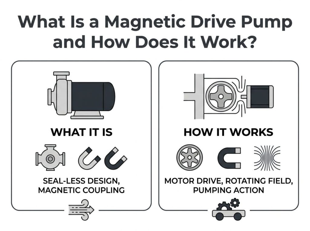
What Is a Magnetic Drive Pump and How Does It Work?
In this guide
- Quick Answer
- What Is a Magnetic Drive Pump?
- How a Magnetic Drive Pump Works
- Magnetic Drive vs. Mechanical Seal vs. Canned Motor
- Engineering Data: Efficiency, Temperature & Coupling Torque
- Best Applications
- How to Select a Magnetic Drive Pump (7 Steps)
- Common Engineering Mistakes
- Troubleshooting: Problem → Cause → Solution
- FAQ
- Why Choose GreenSky?
- References
Quick Answer
A magnetic drive (mag-drive) pump is a sealless centrifugal pump in which an electric motor turns the impeller through a magnetic coupling instead of a mechanical shaft seal. The outer magnet on the motor shaft and the inner magnet on the impeller are separated by a stationary, hermetically sealed containment shell, so there is no rotating shaft penetration and therefore no leak path. That makes mag-drive pumps the default for toxic, flammable, corrosive or high-purity fluids where zero leakage is mandatory — the trade-off being strict no-dry-run and no-solids limits and a 5–15% coupling loss on conductive metallic shells.
What Is a Magnetic Drive Pump?
A magnetic drive pump (MDP, also called a mag-drive or magnetically coupled pump) is a centrifugal pump whose only sealing interface between the process fluid and the atmosphere is a static weld or O-ring joint. There is no dynamic shaft seal. Torque from the drive motor crosses the pressure boundary by magnetic force alone.
The defining components are:
- Outer magnet assembly — mounted on the motor shaft, usually rare-earth (NdFeB or SmCo) segments in alternating poles.
- Containment shell (can / isolation sleeve) — a thin, non-magnetic, pressure-bearing cup that separates the wet inner assembly from the dry motor. This is the single part that defines the pump.
- Inner magnet assembly — mounted on the impeller shaft inside the shell, magnetically locked to the outer assembly.
- Impeller — driven directly by the inner magnet, generating the head.
- Product-lubricated bearings — silicon carbide (SiC) or carbon sleeves that float on the pumped fluid; there are no external grease lines.
Because the fluid chamber is fully enclosed, a mag-drive pump is classified as a sealless pump. The other sealless family is the canned motor pump, where the motor itself is flooded inside the pressure boundary. Heavy-duty petroleum and chemical sealless pumps are governed by API 685 (3rd ed., 2022), which covers both magnetic drive and canned motor designs.
How a Magnetic Drive Pump Works
The power path has four stages. Understanding each is the key to specifying the pump and its motor correctly.
Stage 1 — Motor torque
An electric motor (most often a three-phase induction or a permanent-magnet synchronous (PMSM) machine under a VFD) converts electrical energy into shaft torque T ≈ kt·I, where kt is the torque constant and I the phase current. In variable-speed duty the drive holds current in phase with back-EMF using field-oriented control to maximise torque per ampere.
Stage 2 — Magnetic coupling across the shell
The outer magnet ring spins with the motor. Its rotating field penetrates the non-magnetic shell and drags the inner magnet in lockstep. In a synchronous coupling (permanent-magnet to permanent-magnet) the two rings rotate at identical speed with zero slip — exactly like two bar magnets, one spinning in your hand pulling the other around a pane of glass.
Stage 3 — Impeller and fluid
The inner magnet is fixed to the impeller, so impeller speed equals motor speed (1:1 in a direct-coupled design). Centrifugal action converts that rotation into head and flow. A small fraction of the discharge is internally recirculated to cool the magnets and lubricate the bearings — this minimum continuous flow must never be allowed to drop.
Stage 4 — Synchronous lock and decoupling
Below the coupling’s pull-out torque, the magnets stay locked. If the load torque suddenly exceeds the pull-out rating (blockage, viscous fluid, over-pressure), the poles slip, the coupling decouples, the impeller stops while the motor keeps spinning, and the shell heats rapidly until protection trips. After a decouple event the pump must be stopped and restarted to re-synchronise — it will not self-re-engage.
Magnetic Drive vs. Mechanical Seal vs. Canned Motor
The real buying decision is rarely “mag-drive vs. not” — it is “which sealing technology fits this fluid?” The table ranks the three architectures actually used in chemical and hydrocarbon service.
| Criterion | Magnetic drive pump (MDP) | Mechanical seal pump | Canned motor pump (CMP) |
|---|---|---|---|
| Leakage path | None (static shell only) | Dynamic seal face — wears and leaks | None (static can) |
| Best for | Toxic, flammable, corrosive, high-purity | Water, slurries, high-pressure, low cost | Toxic/flammable, compact skids |
| Coupling loss | 0–15% (shell-dependent) | None | Motor-gap loss only |
| Dry-run tolerance | None — bearing failure | Short periods tolerated | None — bearing failure |
| Solids / slurry | Poor (bearing wear) | Good with flush plan | Poor |
| Maintainability | Motor separable, easy service | Seal field-replaceable | Integrated — often return-to-maker |
| Footprint | Motor + coupling frame | Motor + seal | Smallest (motor in pump) |
| Initial cost | Higher | Lowest | Higher |
| Standards | API 685, ASME B73.3 | API 610, ASME B73.1 | API 685 |
For the drive-motor choice itself — induction, BLDC/servo or PMSM — the same trade study used for other driven equipment applies; the motor is just the prime mover behind the coupling.
Engineering Data: Efficiency, Temperature & Coupling Torque
Efficiency
The impeller hydraulics are identical to a sealed pump; the only added loss is the magnetic coupling. Measured data from field and manufacturer sources:
| Shell material | Conductive? | Eddy-current loss | Typical service limit |
|---|---|---|---|
| Hastelloy C-276 | Yes | 5–15% of coupling rating | High pressure / ~260 °C |
| 316 / 316L stainless | Yes | High (5–15%) | Medium pressure / temperature |
| Reinforced ceramic | No | ≈ 0 | Medium / medium |
| PFA / PTFE-lined | No | ≈ 0 | ≤ ~120–150 °C, aggressive acids |
Net result: a non-metallic-lined mag-drive runs within 1–3% of a comparable sealed pump; a metallic-shell unit gives up 5–15% to eddy currents. Selecting an IE4/IE5 drive motor recovers most of that at the system level.
Temperature and magnet grades
- NdFeB (neodymium): standard grades begin losing strength above ~80 °C, high-temp (SH/UH/EH) grades hold to ~150–200 °C, then irreversibly demagnetize.
- SmCo (samarium-cobalt): stable above 300 °C — the specified choice for services above 150 °C.
- Shell: PFA-lined ~120–150 °C; Hastelloy C up to ~260 °C (500 °F); API 685 is triggered at 150 °C and above.
- Critical check: keep (fluid temperature + eddy-current heating from a metallic shell) under the magnet’s rated temperature, or specify SmCo.
Coupling torque — the square-of-gap rule
The synchronous pull-out torque is set by magnet remanence, pole area and the total magnetic gap. For a fixed magnet, available torque falls roughly with the square of the gap:
T_available ≈ T_ref · (g_ref / g_actual)²
Doubling the shell thickness (the gap) quarters the transmissible torque. This is the core design tension: a thicker shell is needed for higher pressure, but it erodes coupling torque, so shell thickness and pressure rating must be traded against coupling size. Per API 685 the rated coupling torque must cover start-up, rated duty and 120% of best-efficiency-point flow with the safety factor from the standard’s tables.
Bearings
Product-lubricated sleeve bearings are the wear items. SiC vs SiC gives the best chemical resistance for clean aggressive fluids but has limited tolerance for marginal lubrication; carbon vs SiC tolerates brief dry contact better but wears faster; tungsten carbide is used when trace solids are unavoidable. Lifetimes of 3–5 years in clean, compatible fluid are typical; a single dry-start can destroy them.
Best Applications
Specify a magnetic drive pump wherever leakage is unacceptable and the fluid is clean:
- Chemical processing — acids (HCl, H₂SO₄, HNO₃), alkalis, solvents, halogens (PVDF/PFA-lined builds).
- Pharmaceuticals & electronics — high-purity and ultrapure chemicals where motor lubricant must never contact the product; micro mag-drive pumps use small brushless DC motors (Maxon EC 4 at 4 mm diameter, ISO 13485-certified; FAULHABER BX4/BP4 series up to 91% efficient) for dosing and analytical devices.
- Oil & gas / refining — volatile organic compounds and toxic hydrocarbons under API 685, often with secondary containment and ATEX/IECEx motors.
- Water & wastewater treatment — chlorine, ferric chloride, sodium hypochlorite dosing.
- Heat-transfer and plating loops — hot or volatile transfer fluids.
How to Select a Magnetic Drive Pump (7 Steps)
- Confirm fluid hazard. Toxic, flammable, corrosive or expensive → mag-drive. Solids, slurry, viscosity >100–200 cSt → mechanical seal or PD pump instead.
- Define hydraulics. Flow Q, total dynamic head H, specific gravity, viscosity, temperature, and whether duty is continuous (S1) or intermittent (S3/S4 per IEC 60034-1).
- Verify NPSH. Available NPSH must exceed required NPSH by at least ~1 m or a 1.3× ratio; cavitation strips the bearing lubricant film.
- Pick the coupling type. Synchronous PM-PM for clean process duty; eddy-current/torque-ring only for shock-loaded legacy services.
- Select the shell material. Non-metallic (PFA/ceramic) for aggressive acids and zero eddy loss; Hastelloy C for high pressure/temperature and API 685 metallic duty.
- Match the magnet grade to temperature. NdFeB up to ~150 °C; SmCo above 150 °C or wherever eddy heating pushes the sum over the NdFeB limit.
- Size the drive motor. P_motor ≥ 1.15 × pump rated shaft power, choose an IE4/IE5 permanent-magnet motor with a VFD for flow control, and confirm the coupling pull-out torque exceeds 1.2–1.5× worst-case load torque. Add a flow switch or power monitor for dry-run protection.
Common Engineering Mistakes
- Running dry. The most common cause of failure — bearings lose lubrication in seconds. Power monitoring (current drop) reacts faster than a thermal sensor.
- Pumping solids. Particles >50–100 µm destroy product-lubricated bearings. A strainer is mandatory; for slurries, use a sealed pump with a flush plan.
- Undersizing the coupling. Exceeding pull-out torque decouples the pump. Size for start-up and viscous torque, not just rated duty.
- Ignoring eddy-current heating. A metallic shell adds 5–15% heat; at high fluid temperature this can cross the magnet’s demag limit. Use a non-metallic shell or SmCo.
- Thin NPSH margin. Cavitation interrupts the bearing fluid film and causes cumulative damage.
- Metallic shell on high-purity acid. A PFA/ceramic shell eliminates eddy loss and contamination risk — the better choice for most corrosive duties.
- Standard motor on a variable-flow duty. Pairing the pump with a fixed-speed, low-efficiency motor wastes the sealless design’s whole point; use an IE4/IE5 PM motor and VFD.
Troubleshooting: Problem → Cause → Solution
| Problem | Probable cause | Solution |
|---|---|---|
| Motor spins, no flow / impeller stopped | Coupling decoupled — load exceeded pull-out torque (blockage, viscous fluid) | Stop pump, clear obstruction, restart to re-sync; upsize coupling and motor |
| Rapid bearing wear, frequent failures | Dry running or solids in fluid | Install flow switch / power monitor; fit suction strainer <100 µm; switch fluid class |
| Loss of performance / suspected demagnetization | Fluid + eddy heat exceeded magnet temperature | Use SmCo above 150 °C; switch to non-metallic shell to cut eddy loss |
| Containment shell overheating | Eddy currents in metallic shell, low flow | Ensure minimum continuous flow; use non-conductive shell |
| Cavitation noise / vibration | Insufficient NPSH margin | Raise suction head, lower fluid temperature, re-check NPSH |
| Efficiency below expectation | Metallic-shell eddy loss + inefficient motor | Non-metallic shell + IE4/IE5 PM motor with VFD |
FAQ
What is the difference between a magnetic drive pump and a canned motor pump?
Both are sealless, but the coupling differs. A magnetic drive pump (MDP) keeps a standard motor outside the pressure boundary and transmits torque across a containment shell by an outer/inner permanent-magnet coupling — the motor and pump are separate, serviceable parts. A canned motor pump (CMP) integrates the motor and pump into one pressurized, flooded unit: the rotor spins inside the process fluid behind a thin “can” liner, with no external coupling. MDPs are easier to maintain and align to a standard motor; CMPs have a smaller footprint but often must be returned to the maker for repair. API 685 covers both.
Can a magnetic drive pump run dry?
No. The internal bearings are lubricated and cooled by the pumped fluid. Running dry — even for seconds — removes that film and eddy/friction heat can push the magnets above their demagnetization temperature (about 80–150 °C for standard NdFeB) and destroy the bearings. Always fit a flow switch or a motor power monitor (current drops the instant flow is lost) and a suction strainer; power monitoring reacts far faster than a temperature sensor.
What fluids should not be pumped with a mag-drive pump?
Anything with solids, grit or fibres. The product-lubricated bearings (silicon carbide or carbon) are destroyed by particles larger than roughly 50–100 µm or by slurries. For abrasive, solids-laden or high-viscosity (>100–200 cSt) fluids, a mechanically sealed pump with a flush plan (API Plan 32) or a positive-displacement pump is correct. Mag-drive pumps are purpose-built for clean, corrosive, toxic, flammable or high-purity liquids.
How efficient is a magnetic drive pump compared to a sealed pump?
The impeller hydraulics are essentially the same; the difference is the coupling. A non-metallic (PFA/ceramic) containment shell has near-zero eddy-current loss, so overall efficiency is within 1–3% of a comparable sealed pump. A conductive metallic shell (Hastelloy C, 316 SS) induces eddy currents that dissipate 5–15% of the coupling rating as heat. Specifying the drive motor at IE4/IE5 (per IEC 60034-30-1 and the 2027 DOE rule) recovers most of that loss at the system level.
What temperature can a magnetic drive pump handle?
It depends on three components. Magnets: neodymium (NdFeB) begins losing strength above ~80–150 °C by grade and can irreversibly demagnetize; samarium-cobalt (SmCo) stays stable above 300 °C and is specified above 150 °C. Shell: PFA-lined shells top out near 120–150 °C, Hastelloy C near 260 °C (500 °F). You must also add the eddy-current heating from a metallic shell to the fluid temperature and keep the sum under the magnet rating. API 685 is triggered at 150 °C and above.
How do I size the motor for a magnetic drive pump?
Start from the hydraulic power P_hyd = ρ·g·Q·H / η_pump, then add the coupling and motor losses. Specify the motor at ≥1.15× the pump rated shaft power to cover startup and viscous torque, match it to the real duty (continuous vs S1/S3 intermittent per IEC 60034-1), and choose an IE4/IE5 permanent-magnet motor with a variable-frequency drive for flow control. Critically, the magnetic coupling pull-out torque must exceed 1.2–1.5× the worst-case load torque, or the coupling will decouple under load.
Why Choose GreenSky?
Pump OEMs: specify the motor behind the coupling
A magnetic drive pump is only as reliable as the motor and drive that spin its outer magnet. GreenSky supplies the high-efficiency permanent-magnet (BLDC/PMSM) motors and FOC drives that power sealless pumps worldwide — IE4/IE5 PM machines, integrated VFD packages for variable-flow duty, and CE / ATEX-compliant builds for EU and hazardous-area service. We co-engineer the motor, coupling and control as one system so pull-out torque, thermal class and duty cycle are matched to your real process profile rather than guessed from a catalogue.
Talk to our drive engineers about a custom pump-motor package →
References
- IEC 60034-1:2022 — Rotating electrical machines — Part 1: Rating and performance (duty cycles S1–S10, thermal classes, test methods). webstore.iec.ch/publication/6924
- IEC 60034-30-1:2025 — Rotating electrical machines — Efficiency classes (IE1–IE5). webstore.iec.ch/publication/85934
- NEMA MG 1-2021 — Motors and Generators (efficiency tables, thermal classes, North American basis for DOE compliance). nema.org/standards/view/mg-1-motors-and-generators
- U.S. DOE, 10 CFR Part 431 — Energy Efficiency Program for Certain Commercial and Industrial Equipment (motors and pumps; IE4 for 1–750 hp from June 1, 2027). ecfr.gov/current/title-10/chapter-II/subchapter-D/part-431
- API STD 685-2022 — Sealless Centrifugal Pumps for Petroleum, Petrochemical and Gas Industry Services (covers magnetic drive and canned motor pumps). api.org/products-and-services/standards
- ASME B73.3 — Specification for Sealless Horizontal End Suction Metallic Centrifugal Pumps for Chemical Process. asme.org/codes-standards
- Kou Z., Tan Q., He F., Zheng F., Ma X., Wang C., “Analysis of eddy current loss in axial permanent magnet coupling,” 2009 IEEE Int. Conf. on Mechatronics and Automation (ICMA), pp. 1947–1951, doi:10.1109/ICMA.2009.5246649. ieeexplore.ieee.org/document/5246649
- Yon J.M., Mellor P.H., Wrobel R., Booker J.D., Burrow S.G., “Analysis of Semipermeable Containment Sleeve Technology for High-Speed Permanent Magnet Machines,” IEEE Trans. Energy Conversion, vol. 27, no. 3, pp. 646–653, 2012, doi:10.1109/TEC.2012.2202232. ieeexplore.ieee.org/document/6286970
- International Energy Agency (IEA) — Energy Efficiency: Motors (motors consume ~70% of industrial electricity; IE4/IE5 pathway). iea.org/energy-system/industry/motors
- Siemens — SIMOTICS low-voltage IE4/IE5 super-premium motors (permanent-magnet and synchronous-reluctance drive reference). siemens.com/global/en/products/drives/motors/simotics-low-voltage-ie4-ie5.html
