

Understanding electric motors: what you need to know
Quick Answer
An electric motor produces torque across a range of speeds. Current in a winding interacts with a magnetic field to create force on the rotor; at the rotor radius, that force produces torque. Torque multiplied by angular speed gives mechanical power. A nameplate lists the motor’s rated data at a defined operating point. For selection, compare how torque changes with speed, where losses occur, how the load curve intersects the motor curve, and how the motor commutates.
- The torque-speed curve
- Calculating torque from power and speed
- Where motor losses occur
- Finding the operating point
- Four motor families to consider
- Reading a motor nameplate
- Motor starting and inrush current
- Three ways to change motor speed
- Efficiency across the load range
- Six questions for drive sizing
- Common assumptions about motors
- References
- FAQ
A kilowatt rating alone does not tell you whether a motor will suit a machine. This page explains the torque-speed model used in motor selection. For formulas, a worked sizing example, and a troubleshooting guide, see electric motor basics.
The torque-speed curve
An electric motor converts electrical input into torque at a given speed. Current in a winding interacts with a magnetic field and creates force on the rotor. The force acting at the rotor radius produces torque, and torque multiplied by angular speed gives mechanical power.
A motor’s torque changes with speed, and its thermal limit determines how long it can operate at a given load. The nameplate identifies a rated point on that curve. When selecting a motor, check that the motor and load curves intersect at a usable speed and that the operating point stays within the motor’s thermal limits.
Two motors with the same power rating can suit different loads. A 4 kW motor at 1,440 rpm may suit a pump or fan, while a 4 kW geared motor delivering 340 rpm may suit a mixer or hoist. The slower output provides about four times the torque, so the two are not interchangeable.
For a first sizing check, ask how much torque the motor can provide at the required speed, and for how long. A power rating on its own does not answer either question.
Calculating torque from power and speed
Use this conversion to check whether a quoted power, speed, and torque are consistent:
T (N·m) = 9550 × P (kW) / n (rpm)
Applying the formula to the same power rating at several common speeds shows how strongly torque depends on speed.
| Same 4 kW, different speed | Rated torque | What it suits |
|---|---|---|
| 2,880 rpm (2-pole) | 13.3 N·m | Fans, centrifugal pumps at high head, saws |
| 1,440 rpm (4-pole) | 26.5 N·m | The default industrial choice |
| 960 rpm (6-pole) | 39.8 N·m | Conveyors, crushers, larger fans |
| 340 rpm (geared 4-pole) | 112.4 N·m | Mixers, augers, hoists, through a gearbox |
A larger motor can provide more torque at its rated speed, but the speed still depends on supply frequency and pole count. Oversizing can also reduce the load factor, which affects efficiency as described below. Torque, speed, and thermal capacity should be checked separately even when they come together in one motor specification.
To calculate power from a known torque and speed, rearrange the same equation as shown in how to calculate motor torque. The relationship between pole count and synchronous speed is explained in number of poles in a motor.
Where motor losses occur
Motor losses produce heat, which affects how long the motor can operate at a given load. The table lists five common loss mechanisms and how each changes with load. Together they explain why efficiency varies across the operating range.
| Loss | Where it occurs | How it scales | Typical share at rated load |
|---|---|---|---|
| Stator copper | I²R in the winding resistance | ∝ current², so ∝ load² | Around a third |
| Rotor copper | I²R in the rotor bars or cage | ∝ slip × air-gap power | One fifth |
| Iron | Hysteresis and eddy currents in the core | ∝ flux² × frequency, roughly flat with load | One fifth |
| Friction and windage | Bearings and the cooling fan | ∝ speed, and ∝ speed³ for the fan | Around a tenth |
| Stray load | Flux leakage, skin effect, manufacturing spread | ∝ current² | The rest |
At half load, stator copper losses fall to roughly one quarter because they vary with current squared; rotor copper losses also decrease with load, though the exact relationship depends on slip and operating conditions. Iron, friction, and windage losses change much less with load. As a result, many motors reach peak efficiency below full load, often near three-quarters load, though the exact point depends on the motor. A substantially oversized motor may run cooler, but can operate less efficiently.
Speed also affects losses and cooling. Friction and windage losses increase as speed rises. At low speed, a shaft-mounted fan also turns more slowly, reducing cooling. These operating conditions can differ from the rated point used for an efficiency test. IEC 60034-2-1 specifies methods for determining losses and efficiency from tests.
Finding the operating point
Plot torque against speed for both the motor and the load. The operating point is where the curves intersect. If the motor cannot reach that point, the problem may be the required speed or torque, or the motor’s thermal limit, rather than its power rating alone.
Three load curves cover most machines
| Load type | Torque vs speed | Power vs speed | Examples |
|---|---|---|---|
| Constant torque | Flat | ∝ speed | Conveyors, screw pumps, hoists, positive-displacement compressors |
| Variable torque (quadratic) | ∝ speed² | ∝ speed³ | Centrifugal pumps, fans, blowers |
| Constant power | ∝ 1/speed | Flat | Machine-tool spindle above base speed, winders, centre-driven unwinds |
The load curve affects the value of speed control. For a quadratic load, reducing speed by 20% reduces power demand to about 51%, according to the affinity laws. For a constant-torque load, the same speed reduction lowers power demand by about 20%. A fan’s savings estimate therefore should not be applied to a conveyor. Static head can also change the result; see the worked example in pump motor applications.
What happens away from the operating point
If the load requires more torque than the motor can provide during acceleration, the machine may stall and the motor can remain near locked-rotor current. A mismatch at the operating speed can also cause excess current and overheating. Check the motor and load curves before increasing the motor rating; a larger motor with the same speed may not resolve the mismatch.
A motor’s torque-speed curve includes its starting torque, breakdown torque, and slip characteristics. These depend on the motor design, not on its power rating alone. General purpose motor explains the four NEMA design letters used to describe these characteristics.
Four motor families to consider
Some physics texts group motors as piezoelectric, electrostatic, or magnetic. For most machine builders, the practical comparison is among the magnetic motor types used in machinery. Piezoelectric motors appear in camera autofocus and ultrasonic actuators; electrostatic motors are used in MEMS and high-voltage research. Among common industrial motors, a useful distinction is how current is commutated.
Brushed DC: mechanical commutation
A commutator and brushes switch the rotor current mechanically. Starting torque is high and control is as simple as a voltage, which is why the family still owns power tools, automotive auxiliaries and cheap pumps. The cost is the brushes: they wear, they spark, and they set a service interval measured in hundreds to a few thousand hours. How that construction is put together is covered in brushed DC motor.
Brushless DC and PMSM: electronic commutation
A three-phase bridge and rotor-position information replace the brushes and commutator. This removes brush wear, though bearings and other components still require maintenance. Electronic commutation can also improve efficiency, particularly at part load, depending on the motor and controller. The motor needs a controller, whose current limit affects available torque. See how a BLDC motor works for the operating principle.
AC induction: slip commutation
The stator field induces current in the rotor cage without a direct electrical connection. The rotor turns slightly slower than the field; this slip produces torque. Induction motors are widely used in industrial drives because of their robust construction and often low cost per kilowatt. On a direct line supply, their speed stays close to synchronous speed under normal load. A drive is used when variable speed is needed. See squirrel-cage induction motor applications and BLDC versus induction motor for details.
Stepper and servo for positioning
Steppers and servos are often grouped as positioning motors, although they use different control approaches. A stepper holds torque at zero speed and moves in fixed increments without feedback; a servo closes the loop and trades cost for dynamic performance. They are part of motion control, and the stepping principle is explained in how stepper motors work.
| Family | Starting torque | Speed control | Wear parts | Typical first choice for |
|---|---|---|---|---|
| Brushed DC | High, from a simple voltage | Voltage, cheaply | Brushes, hundreds to a few thousand hours | Tools, auxiliaries, low-cost pumps |
| BLDC / PMSM | High, limited by controller current | Electronic, wide range | Bearings only | Battery machines, pumps, mowers, fans |
| AC induction | Moderate, 6 to 8 times inrush on line start | One speed without a drive | Bearings only | Industrial pumps, fans, conveyors |
| Stepper | High holding torque at zero speed | Pulse rate, open loop | Bearings only | Positioning without feedback |
| Servo | High, with overload capability | Closed loop, high bandwidth | Bearings, encoder | Robotics, CNC axes |
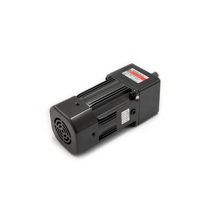
Reading a motor nameplate
A nameplate condenses the motor’s main ratings and operating limits. Start with the fields that determine whether it matches the application: output, speed, current, voltage, frequency, duty, and mounting.
| Field | What it means | How it is misread |
|---|---|---|
| Rated output | Mechanical power at the shaft at the rated point | Taken as electrical input; input is higher by the losses |
| Rated speed | Shaft speed at rated load, slip included | Confused with synchronous speed; a 4-pole 50 Hz induction motor has a 1,500 rpm synchronous speed |
| Rated current | Line current at rated load and rated voltage | Confused with starting current, which is 6 to 8 times higher |
| Voltage and frequency | The pair that sets the flux, not two independent limits | Treated as a range; the ratio is what matters |
| Power factor | Ratio of real to apparent power at rated load | Ignored, then the supply is sized on kW instead of kVA |
| Efficiency class | IE class at the rated point, if in scope of the standard | Taken as the efficiency at every load |
| Duty | S1 continuous is the default; S2 and S3 carry a cycle | Assumed continuous on a motor rated for short-time duty |
| Insulation class | Thermal class of the insulation system | Taken as permitted temperature rise; most are Class F system, Class B rise |
| Enclosure | IP code per IEC 60529 | Taken as a quality grade rather than a test condition |
| Mounting | Foot, flange or both, with the frame dimensions that go with it | Assumed interchangeable across NEMA and IEC frames |
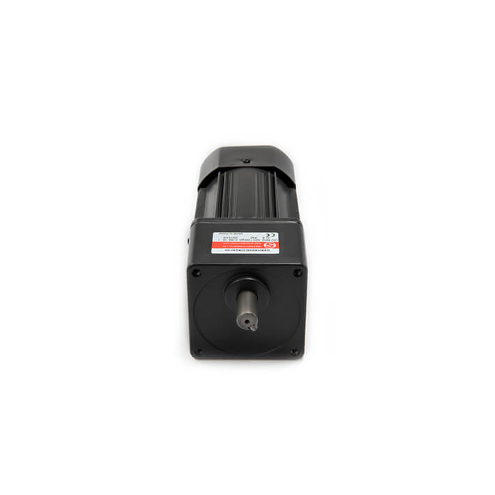
Check rated current when sizing protection and cables, but account separately for starting current. Voltage and frequency should also be considered together. A 400 V, 50 Hz supply and a 480 V, 60 Hz supply both have a 8 V/Hz ratio, but the motor’s rated voltage, frequency, and design determine whether it can operate on either supply. IEC 60034-1 covers ratings and performance tolerances.
Motor starting and inrush current
At standstill, an induction motor has little back-EMF to limit current, so winding impedance largely determines the initial current. Depending on its design and the supply, direct-on-line starting current is commonly around six to eight times rated current, then falls as the motor accelerates. This is expected behavior, but it can trip protection if starting conditions and settings are not coordinated.
Protection, cabling, and the supply must accommodate the starting current and duration. A protection device set too close to rated current may trip during startup. A long start can overheat an undersized cable. A weak supply may experience a voltage dip, reducing available starting torque.
The starting method is a separate purchase decision from the motor:
- Direct on line: full voltage, starting torque, and inrush. It is the simplest and least expensive option, and suits many small machines.
- Star-delta: reduces starting current and starting torque compared with direct-on-line starting, often to about one third. It suits loads that can accelerate with the reduced torque.
- Soft starter: ramps the applied voltage to reduce starting current and mechanical shock. Lower voltage also reduces starting torque, so check the load’s breakaway requirement.
- Variable frequency drive: controls frequency and voltage to manage speed and torque during startup. It avoids the direct-on-line inrush, though the drive and supply still carry current while accelerating the load.
Because a running motor that loses one phase keeps turning on the remaining two, a start failure and a running failure are different faults with different causes. The supply-side diagnostics for both are in general purpose motor; the routine inspection items are in maintaining a three-phase asynchronous motor.
Three ways to change motor speed
The output speed depends on the motor and the equipment between it and the load. Three common options are pole changing, a gearbox, and a variable frequency drive. Each has different costs, efficiency, and torque characteristics.
| Method | How it works | What you get | What it costs |
|---|---|---|---|
| Pole changing | Reconnect the stator winding for a different pole count | Two or three discrete speeds, full torque at each | Cheap, but no continuous range |
| Gearbox | Trade speed for torque through a ratio | Any fixed output speed, torque multiplied by the ratio | 5% to 15% of the power, plus volume and cost |
| Variable frequency drive | Change the electrical frequency, keeping V/f roughly constant | Continuous speed, controlled torque from zero | Drive cost, plus motor derating and bearing current |
Below base speed, a drive can maintain approximately constant torque when voltage and frequency are controlled together and the motor is properly cooled. Some motor-drive combinations can provide near-rated torque at 10% speed; above base speed, voltage is limited and torque generally falls as speed rises. At 150% speed, available torque may be only a fraction of rated torque. Actual limits depend on the motor and drive. See how a variable speed motor works.
A gearbox trades speed for torque and loses some power through inefficiency. Output torque is approximately input torque multiplied by the ratio and gearbox efficiency; output speed is input speed divided by the ratio. For example, a 10:1 gearbox at 90% efficiency would turn 26.5 N·m at 1,440 rpm into about 240 N·m at 144 rpm. The choice between gearing and another motor family is discussed in gear motor versus BLDC motor.
Efficiency across the load range
Efficiency is output divided by input at one operating point, and the point is stated in the standard. IEC 60034-30-1 defines efficiency classes for covered single-speed line-operated AC motors rated from 0.12 kW to 1,000 kW. The class should not be read as the motor’s efficiency at every load.
The loss balance changes with load. Copper losses decrease as current falls, while iron and windage losses change less, so efficiency often peaks below full load. A motor that is substantially oversized may spend more time away from that peak. Check the efficiency curve for the specific motor.
In the European Union, Regulation 2019/1781 sets minimum efficiency requirements for specified motor types and power ranges. It requires IE3 for covered three-phase motors from 0.75 kW to 1,000 kW from July 2021, and IE4 for certain covered motors from 75 kW to 200 kW from July 2023. The regulation has exclusions, so check its scope before applying these requirements to a particular motor. For the distinction between line-operated and electronically commutated machines, see motor efficiency class.
Annual operating hours and load matter when comparing efficiency classes. The source estimate gives a 15 kW IE3 motor about a 1.5 percentage-point efficiency advantage over IE2; at 4,000 hours per year, that amounts to a few hundred kilowatt-hours. Confirm the exact motor efficiencies and load profile before using the estimate. Incorrect speed or prolonged low-load operation can also affect energy use, sometimes more than the difference between classes.
Six questions for drive sizing
A useful motor specification answers six questions. A supplier with all six answers may be able to quote in a day; a power rating alone leaves five important selection details to estimate.
- What torque at what speed? Specify both values. If the machine is already built, measured torque at the output shaft is the most useful number you can send.
- Which load curve? Constant torque, quadratic or constant power. This decides whether variable speed is worth anything and how much starting torque is needed.
- What duty and how many starts? Continuous or intermittent, starts per hour, and whether the load breaks away under torque. Heat comes from both running and starting, and a motor rated for one may not survive the other.
- What environment? Ambient range, altitude, ingress, wash-down, corrosion. The standard conditions and the derating that follows from leaving them are in general purpose motor.
- What supply? Give the voltage, frequency, and supply quality. Voltage imbalance and harmonics can affect motor performance.
- What life and service interval? A brushless drive that never needs attention and a brushed drive that needs brushes every 1,500 hours are different total costs at the same purchase price.
The first two answers help narrow the motor family; the supply, environment, and service requirements help determine whether a candidate will suit the installation. For product examples, see high-torque AC gear motors and the high-torque BLDC technical guide.
Common assumptions about motors
| Belief | What the motor does |
|---|---|
| “More poles means more torque for free” | It is arithmetic, not a gift. At the same power, doubling the pole count halves the speed and doubles the torque, while mass, volume and price rise with it. |
| “A bigger motor is safer” | Past roughly three-quarters load, efficiency falls and power factor collapses. An oversized motor runs cooler but wastes reactive power and money for its whole life. |
| “A higher IE class means a cheaper bill” | Only if the hours and the load factor support it. The class is defined at the rated point; a lightly loaded motor never reaches it. |
| “A drive always saves energy” | It saves on quadratic loads with low static head. On constant-torque loads the saving is proportional to the speed reduction, and on a high-static-head booster the flow may collapse before the saving appears. |
| “BLDC is a different category from DC” | BLDC is a DC motor with electronic commutation. The useful distinction is whether commutation is mechanical or electronic, rather than the letters in the name. |
| “A gearbox increases power” | It trades speed for torque and loses a little in the trade. Power out is always below power in. |
These assumptions often arise because a rule that works for one load or operating point may not work for another. Comparing torque and speed curves helps show where the difference matters.
References
- International Electrotechnical Commission. (2022). IEC 60034-1:2022: Rotating electrical machines, Part 1: Rating and performance. IEC. https://webstore.iec.ch/en/publication/65446
- International Electrotechnical Commission. (2014). IEC 60034-2-1:2014: Standard methods for determining losses and efficiency from tests. IEC. https://webstore.iec.ch/en/publication/121
- International Electrotechnical Commission. (2025). IEC 60034-30-1:2025: Efficiency classes of line operated AC motors (IE code). IEC. https://webstore.iec.ch/en/publication/91195
- International Electrotechnical Commission. (2016). IEC TS 60034-30-2:2016: Efficiency classes of variable speed AC motors (IE code). IEC. https://webstore.iec.ch/en/publication/30830
- International Electrotechnical Commission. (2013). IEC 60529:1989+AMD2:2013: Degrees of protection provided by enclosures (IP code). IEC. https://webstore.iec.ch/en/publication/2452
- International Electrotechnical Commission. (2017). IEC 61800-9-2:2017: Ecodesign for power drive systems, motor starters and power electronics. IEC. https://webstore.iec.ch/en/publication/111276
- National Electrical Manufacturers Association. (2021). NEMA MG 1: Motors and Generators. NEMA. https://www.nema.org/standards
- European Parliament and Council. (2019). Commission Regulation (EU) 2019/1781 laying down ecodesign requirements for electric motors and variable speed drives. Official Journal of the EU. https://eur-lex.europa.eu/eli/reg/2019/1781/oj
- European Parliament and Council. (2023). Regulation (EU) 2023/1230 on machinery and repealing Directive 2006/42/EC. Official Journal of the EU. https://eur-lex.europa.eu/eli/reg/2023/1230/oj
- U.S. Department of Energy. (2024). Motor systems: energy efficiency and system optimisation. Advanced Manufacturing Office. https://www.energy.gov/eere/amo/motor-systems
FAQ
Q: What should I understand first about an electric motor?
Start with the torque and speed the load requires. A 4 kW motor delivers about 26.5 N·m at 1,440 rpm; at the same output power, 340 rpm corresponds to about 112 N·m before gearbox losses. The power rating alone does not show whether either motor will suit a particular load.
Q: Why does the same power give different torque at different speeds?
Torque is power divided by speed: T = 9550 × P / n. At the same power, doubling speed halves torque. For example, a 90 W mower blade motor at 4,500 rpm produces 0.19 N·m, while a 32 W wheel motor at 57 rpm produces 5.4 N·m. That is roughly 28 times the torque from about one third of the power.
Q: How do the main motor families differ?
They differ in how current is commutated, which affects starting torque, speed control, and maintenance. Brushed DC motors use mechanical commutation and require brush replacement. BLDC and PMSM motors use electronic commutation. Induction motors rely on slip between the rotor and magnetic field and generally need a drive for variable-speed operation. Steppers and servos are commonly selected for positioning.
Q: Why does a motor draw six to eight times its rated current at start?
At standstill, back-EMF is low, so direct-on-line starting current can be much higher than rated current. The starting current is expected, but the protection, cable, and supply must be suitable for the startup conditions. Repeated trips can point to supply, protection, or load issues and need diagnosis. A motor that runs normally after starting can still trip a breaker during its morning startup.
Q: Does a gearbox increase power?
A gearbox trades speed for torque and loses some power through inefficiency. Output torque is approximately input torque multiplied by the ratio and gearbox efficiency, while output speed is input speed divided by the ratio. Power out is therefore below power in. A gearmotor suits a machine that needs low speed and high torque.
Q: Is a higher efficiency class always cheaper to run?
Not necessarily. Compare the actual efficiency curves, annual hours, load, and purchase price. A motor operating at a quarter load may have a different efficiency from its rated-point value, and low annual usage can limit the energy savings available to repay a higher purchase cost.
For help matching a duty point to a motor family, send the torque, speed, duty cycle, and supply details through our contact page.