
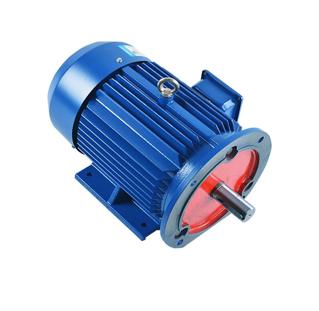
How to Maintain the Three-Phase Asynchronous (Induction) Motor: A Preventive Maintenance Guide
Quick Answer
Maintaining a three-phase asynchronous motor means running a scheduled preventive maintenance (PM) program — not waiting for failure. The core loop is: (1) check current, temperature and noise every shift; (2) measure insulation resistance with a 500 V megger (IEEE 43-2013) and confirm it exceeds 1 MΩ + 1 MΩ per kV rated with a polarization index (PI) above 2; (3) keep bearings lubricated on a speed-based interval without over-greasing; (4) trend vibration (ISO 20816) and infrared temperature to catch faults early. Built to IEC 60034 and NEMA MG 1, a disciplined PM plan typically cuts unplanned downtime by half and roughly doubles insulation and bearing life through the 10 °C rule.
What Is Three-Phase Asynchronous Motor Maintenance?
A three-phase asynchronous motor — more commonly called an induction motor — converts three-phase AC into rotating torque through slip between the stator field and a short-circuited rotor. “Maintenance” here is not a single task but a managed program of inspection, lubrication, testing and condition monitoring applied on a fixed schedule. The goal is to keep the machine within its IEC 60034 and NEMA MG 1 design envelope so it reaches (or exceeds) its intended service life instead of failing mid-duty.
Reactive vs Preventive vs Predictive Maintenance
There are three maturity levels, and most plants should aim for at least preventive with selective predictive elements:
| Strategy | Trigger | Cost profile | Typical downtime | Best for |
|---|---|---|---|---|
| Reactive (run-to-failure) | Breakdown only | Low planned cost, high unplanned cost | Long, unpredictable | Non-critical, cheap spares |
| Preventive (PM) | Fixed calendar/run-hours | Moderate, predictable | Short, scheduled | Most general-purpose motors |
| Predictive (PdM) | Condition threshold (vibration, temp, insulation) | Higher instrumentation, lowest failure cost | Minimal | Critical, high-power drives |
Why Maintenance Is an Engineering Problem, Not Housekeeping
Two physical mechanisms dominate induction-motor aging, and both are quantifiable:
- Insulation thermal aging — the 10 °C rule: every 10 °C of sustained winding-temperature rise above rating roughly halves insulation life (IEC 60034-1 / IEEE 117). A motor run 20 °C hot can lose ~75 % of its insulation life.
- Bearing wear — governed by load, speed and contamination. Bearing L10 life follows the load-life relation L10h = 10⁶/60n · (C/P)ᵖ (p≈3 for ball, 10/3 for roller, per SKF / ISO 281). Over-lubrication and ingressed contamination are the top avoidable killers.
How a Maintenance Program Works: The Failure-Chain Principle
Most failures do not appear suddenly — they propagate along a chain: stress → degradation → symptom → fault → failure. A good PM program interrupts the chain by measuring the symptom before it becomes a fault. Here is the step-by-step logic that underpins every checklist below.
Step 1 — Establish the Baseline
When the motor is healthy and at operating temperature, record: no-load and loaded current, vibration RMS at each bearing, casing temperature, and a megger reading. These baselines are your reference for “normal.”
Step 2 — Monitor the Leading Indicators
Three signals predict ~80 % of failures:
- Current imbalance — tracks supply imbalance and rotor/connection problems (NEMA MG 1 allows ≤1 % voltage imbalance; current imbalance then stays ≤6–10 %).
- Vibration trend — bearing defects, imbalance and misalignment all show up here first (ISO 20816 limits).
- Insulation resistance trend — moisture and thermal aging drop R and the polarization index before a short occurs (IEEE 43).
Step 3 — Act Before the Threshold
When a reading crosses its limit (e.g. vibration enters ISO zone C, or PI falls below 2), schedule intervention inside a planned window. This converts a future emergency into a controlled service stop.
Step 4 — Close the Loop with Records
Each inspection feeds a log. Over months the trend — not a single reading — tells you whether lubrication interval, load or environment needs to change.
Maintenance Schedule & Comparison Tables
1. Preventive Maintenance Interval Table
| Frequency | Task | Tool / Method | Acceptance criterion |
|---|---|---|---|
| Daily / per shift | Listen for abnormal noise, check for leaks, feel casing temp, log amp draw | Ears, IR gun, ammeter | Current within ±10 % of baseline; casing < 80 °C typical |
| Monthly | Vibration reading at both bearings, check coupling alignment, tighten Terminals | Vibration meter, laser aligner | ISO 20816 zone A/B; alignment < 0.05 mm |
| Quarterly | Insulation resistance (megger), grease check / top-up, IR thermography | 500 V megger, thermal camera | R > 1 + U_kV MΩ; PI > 2; hot spots < 15 °C above ambient diff |
| Annual | Full strip, bearing replacement, winding clean & dry, re-megger, re-align | Workshop, oven, megger | New bearings seated; R back to baseline; balanced |
2. Insulation Resistance Criteria (IEEE 43-2013)
| Rated voltage | Minimum acceptable R | Polarization index PI = R₁₀/R₁ | Verdict |
|---|---|---|---|
| ≤ 1 kV (use 500 V DC test) | ≥ 1 MΩ + 1 MΩ per kV rated | — | Absolute floor |
| 400 V (0.4 kV) motor | ≥ 1.4 MΩ | — | Pass floor |
| Any LV motor | — | PI > 2.0 | Healthy, dry |
| Any LV motor | — | 1.0–2.0 | Suspect — retest after drying |
| Any LV motor | — | < 1.0 | Failed — do not energize |
3. Vibration Severity by ISO 20816 (RMS velocity, mm/s)
| Zone | Velocity RMS (mm/s) | Meaning | Action |
|---|---|---|---|
| A | ≤ 1.4 | Good | No action |
| B | 1.4 – 2.8 | Acceptable for continuous use | Monitor |
| C | 2.8 – 4.5 | Damaging over long term | Plan repair |
| D | > 4.5 | Unacceptable | Stop & repair |
4. Bearing Re-lubrication Interval vs Speed & Size
| Bearing bore d (mm) | At 1500 rpm | At 3000 rpm | Note |
|---|---|---|---|
| 30 | ~ 9,000 h | ~ 4,500 h | Small, high-speed → shorter |
| 60 | ~ 14,000 h | ~ 7,000 h | Typical IEC frame |
| 100 | ~ 20,000 h | ~ 10,000 h | Large, low-speed → longer |
Intervals are ballpark from the SKF relation t ≈ K·10⁶/(n·√d). Sealed “lubed-for-life” bearings need none; re-lubricatable types need the right grease volume (fill 1/3–1/2 of the free cavity, less at high speed).
5. This Article vs “Common Faults & Treatment”
| Dimension | Maintenance (this guide) | Faults & Treatment (sister post) |
|---|---|---|
| Intent | Prevent failure before it happens | Diagnose & fix after symptoms appear |
| Typical reading | Trend vs baseline, scheduled | Symptom → subsystem → cause |
| Core tools | Megger, vib meter, IR cam, lube | Megger, clamp, growler, disassembly |
| Best linked from | Asset managers, planners | Technicians, emergency repair |
Engineering Data: Formulas, Limits & Worked Examples
Key Formulas
| Quantity | Formula | Notes |
|---|---|---|
| Min insulation resistance | Rmin = 1 + UkV (MΩ) | IEEE 43 floor for LV motors |
| Polarization index | PI = R(10 min) / R(1 min) | > 2 healthy; < 1 fail |
| Rated current | I = P / (√3 · U · η · cosφ) | 3-phase; verify against nameplate |
| Shaft torque | T = 9550 · P(kW) / n(rpm) | N·m |
| Slip | s = (Ns − Nr) / Ns | Ns = 120f / p |
| Bearing L10 life | L10h = 10⁶/(60n) · (C/P)ᵖ | p≈3 ball, 10/3 roller (ISO 281) |
| Re-lube interval | t ≈ K · 10⁶/(n · √d) | d = bore mm; K from duty |
Worked Example — 7.5 kW, 400 V, 4-Pole Motor
Given a 7.5 kW, 400 V, 50 Hz, 4-pole machine at η = 0.90, cosφ = 0.85, running at 1440 rpm:
- Rated current: I = 7500 / (1.732 × 400 × 0.90 × 0.85) = 14.1 A. A healthy amp draw should stay within ±10 % of this.
- Shaft torque: T = 9550 × 7.5 / 1440 = 49.7 N·m.
- Slip: Ns = 120×50/4 = 1500 rpm → s = (1500 − 1440)/1500 = 4.0 % (normal for a standard induction motor).
Worked Example — Insulation & Vibration Pass/Fail
- Insulation: For a 400 V motor, IEEE 43 floor is 1.4 MΩ. A reading of 5 MΩ passes the floor, but if PI = 8 MΩ/5 MΩ = 1.6, it is suspect — dry the winding and retest; do not assume it is safe.
- Vibration: A measured 3.2 mm/s RMS sits in ISO 20816 zone C — plan a bearing or alignment intervention before it reaches zone D.
Insulation Temperature Classes (IEC 60034-1)
| Class | Max winding temp | Max temp rise (40 °C ambient) | Typical service use |
|---|---|---|---|
| B | 130 °C | 80 K | General-purpose, economical |
| F | 155 °C | 100 K | Common; often run at Class B rise for margin |
| H | 180 °C | 125 K | Harsh / high-ambient duty |
A motor with Class F insulation run at a Class B (80 K) rise carries a large thermal margin — per the 10 °C rule this roughly doubles insulation life versus running at the full F limit. This is why “Class F, run B” is the reliability-minded default.
Best Applications: Where Maintenance Pays Off Most
Not every motor needs the same program. The table maps duty type to the maintenance elements that matter most.
| Application | Failure cost if down | Priority checks | Why |
|---|---|---|---|
| Centrifugal pumps | High (process stop) | Vibration, seal leak, current | Misalignment & cavitation dominate |
| HVAC / cooling fans | Medium | Bearing lube, belt tension | Long run-hours, easy to ignore |
| Air compressors | High | Vibration, insulation, cooling | Continuous, heat-sensitive |
| Conveyors | Medium | Current balance, coupling | Mechanical load swings |
| Machine tools / spindles | Very high | Vibration (tight), alignment | Precision & bearing life critical |
| Hazardous-area / EX | Severe | Thermal, insulation, enclosure | Safety-regulated |
Step-by-Step: Build a Maintenance Plan for Your Motor
Step 1 — Classify Criticality
Score each motor by power, downtime cost and redundancy. Critical units get predictive add-ons (online vibration, thermal); non-critical get calendar PM only.
Step 2 — Capture the Healthy Baseline
Record current, vibration at each bearing, casing temp and a megger reading at operating temperature. Store as the “normal” reference.
Step 3 — Set Intervals from Speed & Duty
Use the re-lubrication table and a quarterly insulation/thermography cadence; tighten intervals for hot, dirty or high-speed sites.
Step 4 — Choose Monitoring Tools
| Tool | Measures | Standard | Buy vs skip |
|---|---|---|---|
| 500 V megger | Insulation R, PI | IEEE 43 | Buy — essential |
| Vibration meter | RMS velocity, spectrum | ISO 20816 | Buy — top predictor |
| IR thermometer / camera | Surface temp, hot spots | — | Buy — cheap, fast |
| Clamp ammeter | Current, imbalance | NEMA MG 1 | Buy — daily check |
| Online CMS | Continuous trend | ISO 13374 | Critical units only |
Step 5 — Define Thresholds & Responses
Write the limits into the work order: vibration > 2.8 mm/s → plan repair; PI < 2 → dry & retest; current imbalance > 10 % → check supply/rotor.
Step 6 — Log, Review, Improve
Keep a running log. A drifting trend beats a single bad reading — review quarterly and adjust intervals.
Common Engineering Mistakes in Motor Maintenance
| Mistake | Why it hurts | Better practice |
|---|---|---|
| Over-greasing bearings | Raises temp, blows seals, cages churn grease | Correct volume, purge old grease, never “just add more” |
| Judging health by casing temp alone | Winding runs far hotter than the frame | Use megger + IR; trend winding via resistance/temp |
| One-shot megger, ignoring PI | R can pass while moisture hides | Always compute PI = R10/R1 |
| Skipping alignment after reinstall | Misalignment is a top vibration cause | Laser-align to < 0.05 mm |
| Cleaning windings with wrong solvent | Attacks insulation, leaves residue | Use approved cleaner; dry before re-energizing |
| No baseline = no trend | Single readings are meaningless | Baseline at commissioning, trend thereafter |
Troubleshooting: Symptom → Cause → Solution
| Problem (from monitoring) | Likely cause | Solution |
|---|---|---|
| Low insulation R, PI < 2 | Moisture, contamination, thermal aging | Dry/clean winding, retest; if PI < 1 do not energize |
| Vibration in zone C/D | Worn bearing, unbalance, misalignment | Replace bearing, balance rotor, laser-align coupling |
| Bearing runs hot | Over-greased, under-greased, poor alignment | Correct grease volume, purge old, re-align |
| Current imbalance > 10 % | Supply voltage imbalance, rotor bar defect | Correct supply; MCSA rotor test; check connections |
| Casing abnormally hot | Overload, blocked ventilation, aging winding | Reduce load, clean cooling path, megger winding |
| Electromagnetic hum / noise | Air-gap eccentricity, harmonics | Check mounting/bearing, add line filter if VFD |
| Grease leaking from seals | Seal failure, over-filled | Replace seals, reduce fill to 1/3–1/2 cavity |
| Won’t start / stalls | Undervoltage, mechanical jam, winding fault | Verify supply, free the load, resistance/megger test |
Frequently Asked Questions
How often should I megger a three-phase motor?
At a minimum on your quarterly PM cycle, and immediately after any flood, washdown or long idle period. IEEE 43-2013 is the reference; trend R and the polarization index (PI) rather than trusting a single reading.
What vibration level is acceptable for an induction motor?
Per ISO 20816, RMS velocity ≤ 1.4 mm/s (zone A) is good and ≤ 2.8 mm/s (zone B) is acceptable for continuous running. Above 2.8 mm/s (zone C) plan a repair; above 4.5 mm/s (zone D) stop the machine.
Can you over-grease a motor bearing?
Yes, and it is a common mistake. Excess grease raises temperature, can blow the seal and churns the cage. Use the correct volume (roughly 1/3–1/2 of the free cavity), purge the old grease, and follow the speed/size interval table.
What does a low polarization index mean?
A PI below 2 suggests moisture or contamination even if the resistance floor is met; dry and retest. A PI below 1.0 means the winding is unsafe to energize. Always compute PI = R(10 min) / R(1 min).
Does preventive maintenance actually save money?
Yes. A disciplined PM program typically halves unplanned downtime and, through the 10 °C rule, roughly doubles insulation and bearing life. Since energy is 95–97 % of a motor’s lifetime cost, avoiding a single forced outage usually pays for the program many times over.
Repair or replace an old failing motor?
Replace with a new IE3/IE4 unit in most cases. Rewinding typically loses 1–3 % efficiency, and a new high-efficiency motor’s energy saving usually recovers its cost within a year or two of continuous duty.
Why Choose Greensky for Reliable Three-Phase Motors?
Greensky is a Chinese B2B motor manufacturer supplying IE3 and IE4 three-phase asynchronous (induction) motors (0.75–315 kW, 2/4/6/8-pole) built to IEC 60034 and NEMA MG 1, with Class F insulation run at Class B rise for the long service life that a maintenance program is meant to protect. Our machines use SKF-grade bearings sized for the L10h life in this guide, and we offer IEC B5/B14 and NEMA C-face flanges plus integrated gearboxes for drop-in replacement.
For asset managers, we supply nameplate data, baseline test points and matching spares so your PM plan starts with a clean baseline. Low MOQ and flexible mounting make Greensky a practical补充 to the tier-1 brands for fleets, replacements and custom OEM drives.
Related Reading
References
- IEEE 43-2013 — Recommended Practice for Testing Insulation Resistance of Rotating Machinery: https://standards.ieee.org/ieee/43/46353/
- NEMA MG 1-2021 — Motors and Generators (application & maintenance guidance): https://www.nema.org/standards/view/mg-1-motors-and-generators
- IEC 60034-1 — Rotating electrical machines, insulation temperature classes: https://webstore.iec.ch/publication/5698
- IEC 60034-30-1 — Efficiency classes IE1–IE4 for line-operated AC motors: https://webstore.iec.ch/publication/2376
- ISO 20816-1 — Mechanical vibration — Measurement and evaluation of machine vibration: https://www.iso.org/standard/63611.html
- SKF — Bearing maintenance, lubrication and L10h life: https://www.skf.com/us/products/bearings-units-housings/roller-bearings
- U.S. DOE — Electric Motors (EISA compliance & efficiency): https://www.energy.gov/eere/amo/electric-motors
- Siemens — SIMOTICS low-voltage motors & maintenance: https://www.siemens.com/global/en/products/drives/motors/low-voltage.html
- ABB — IEC 60034-30-1 efficiency & motor care technical note: https://library.e.abb.com/public/ea5c8669a89644158723ebb22994f5e4/TM025%20EN%2008-2014%20IEC60034-30-1_lowres.pdf
- IEA — Energy Efficiency: Motors (global motor electricity use): https://www.iea.org/topics/energy-efficiency
