
How Does a Micro Magnetic Pump Work? Compact, Low-Flow, Low-Power Fluid Control
In this guide
- Quick Answer
- What Is a Micro Magnetic Pump?
- How a Micro Magnetic Pump Works (step by step)
- Centrifugal vs. Gear: Two Micro Architectures
- Micro Magnetic Pump vs. Peristaltic & Syringe Pumps
- Engineering Data: Flow, Power, Efficiency, Limits
- Best Applications: Miniature Fluid Systems & OEM Equipment
- How to Select a Micro Magnetic Pump (8 Steps)
- Common Engineering Mistakes
- Troubleshooting: Problem → Cause → Solution
- FAQ
- Why Choose GreenSky?
- References
Quick Answer
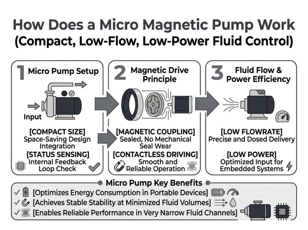
A micro magnetic pump is a sealless, magnetically coupled pump shrunk to fit compact OEM equipment. A tiny BLDC or stepper micromotor spins an outer magnet; its field crosses a stationary containment shell and drags an inner magnet — fixed to the impeller or gear set — with no shaft penetrating the fluid. That removes the mechanical seal, so there is zero leakage. Because flow tracks motor speed, these pumps deliver low flow from single-digit µL/min with low power (often a few watts, sometimes under a milliwatt in research devices), which is why they anchor miniature fluid systems in medical analyzers, electronics cooling loops, fuel cells, portable instruments and other space- and power-constrained OEM products.
What Is a Micro Magnetic Pump?
A micro magnetic pump is not a separate pump family — it is the same sealless magnetic-drive principle used in large magnetic drive (centrifugal) pumps and magnetic gear pumps, scaled down to a compact package for low-flow, low-power duty. The defining features are size, flow and power, not a different working principle:
- Compact size. Heads often measure only a few centimetres across and weigh under 0.5 kg (Micropump GJ heads, for example, are 0.34–1.2 kg with 1/8″ ports), so they drop into instruments and handheld devices.
- Low flow. Continuous flow spans roughly 0.0085 L/min up to a few L/min; gear-type designs meter from several mL/min down to µL/min per revolution at low speed.
- Low power. With no dynamic shaft-seal drag, drive power is small — OEM units use 3.7–48 VDC BLDC motors drawing a few watts to ~50 W, and lab prototypes report 170 µW to 200 mW.
- Sealless. Like its larger relatives, the only seal between fluid and atmosphere is a static weld or O-ring at the containment shell, not a rotating shaft seal.
How a Micro Magnetic Pump Works (step by step)
The power path is identical in concept to a full-size mag-drive pump, just compressed into a small head. Follow the torque from the battery or supply to the fluid:
- Micromotor spins. A compact BLDC (or stepper) micromotor — often 8–22 mm in diameter, sometimes with an integrated speed controller — drives the outer magnet assembly. Brushless drives from Maxon (ECX series, ISO 13485) and FAULHABER (B-Micro, down to 3 mm) are typical reference platforms.
- Field crosses the shell. The outer permanent-magnet ring creates a rotating magnetic field. That field penetrates the thin, non-magnetic containment shell (can), which is the single part that separates the wet side from the dry motor.
- Inner magnet is dragged in lockstep. The field pulls the inner magnet — and the impeller (centrifugal) or gear set (positive displacement) rigidly attached to it — around at identical speed with zero slip (synchronous coupling).
- Fluid is moved. In a centrifugal micro pump, the impeller throws fluid outward by centrifugal action into the volute and out the discharge; in a gear type, fluid is trapped between gear teeth and the bore and carried from inlet to outlet (see magnetic gear pump mechanics).
- No seal, no leak. Because the motor shaft never crosses the wetted boundary, there is no mechanical seal to leak or wear. Only static seals (O-ring/weld at the shell) remain.
- Flow is set by RPM. For centrifugal:
Q ∝ N,H ∝ N²,P ∝ N³(affinity laws). For gear:Q = D × N × ηv. So a small change in drive current/RPM gives precise, repeatable low-flow control — ideal for metering in miniature systems.
The coupling also acts as a built-in overload clutch: below its pull-out torque (which scales roughly with the inverse square of the air gap, T ∝ 1/g²) the magnets stay locked; above it they slip and decouple, protecting the gears and motor from jamming.
Centrifugal vs. Gear: Two Micro Architectures
“Micro magnetic pump” covers two internal architectures. Pick by what matters most — smooth low-flow metering (gear) or simple, higher-flow transfer (centrifugal):
| Attribute | Micro magnetic centrifugal pump | Micro magnetic gear pump |
|---|---|---|
| Pumping action | Impeller, centrifugal throw | Two meshing gears, positive displacement |
| Flow vs. pressure | Flow falls as discharge pressure rises | Flow nearly independent of pressure |
| Best for | Cooling loops, transfer, circulation | Precision dosing, metering, reagents |
| Flow range | ~0.05–6.8 L/min (typical) | µL/min to ~26 mL/rev × N |
| Pulsation | Smooth | Pulseless (fixed volume/rev) |
| Pressure capability | Lower per size (volute limited) | Higher at low flow (up to ~20–40 bar in gear designs) |
| Viscosity handling | Poor above a few hundred cP | Better; gears move thicker fluids |
Both share the sealless magnetic coupling; the difference is only the rotor doing the pumping. Gear types appear wherever flow must stay constant against varying back-pressure — reagent dosing, diagnostic sample handling, fuel-cell recirculation.
Micro Magnetic Pump vs. Peristaltic & Syringe Pumps
For compact OEM fluid systems the real alternatives are peristaltic and syringe pumps. The magnetic pump wins on contamination control, accuracy and service life:
| Feature | Micro magnetic pump | Peristaltic pump | Syringe pump |
|---|---|---|---|
| Seal / leak path | Static only — sealless | Tube compression, occasional weep | Plunger seal, periodic service |
| Flow precision | Excellent, pulseless | Moderate, pulsatile | Excellent but intermittent |
| Sterility / contamination | Fully sealed fluid path | Tube change can introduce risk | Good; refill breaks continuity |
| Maintenance | Very low (no wear items in wet path) | High — tubing is a consumable | Medium — seal/refill |
| Continuous operation | Yes | Yes | No — stops at end of stroke |
| Footprint in OEM | Small, permanent mount | Motor + roller head | Larger; linear actuator |
| Low-viscosity accuracy | ±0.3% to ±2% | ±1%+ (tube rebound slip) | High |
| Service life | Long (20,000+ h typical) | Short (tube life) | Medium |
For thin, aggressive or high-purity liquids under 10 cP, magnetic pumps beat peristaltic accuracy by roughly 2× and cut maintenance cost by ~40% versus tubing-based systems — the reason diagnostic and dosing OEMs keep migrating to magnetic micro pumps.
Engineering Data: Flow, Power, Efficiency, Limits
The numbers that matter when you size a compact, low-power unit:
| Parameter | Typical micro magnetic pump range | Notes |
|---|---|---|
| Flow rate | 0.0085 L/min to ~6.8 L/min; gear down to µL/min | Gear: Q = D × N × ηv, ηv ≈ 80–93% |
| Drive voltage | 3.7–48 VDC (BLDC) | Battery-friendly for portable OEM |
| Drive power | ~170 µW (research) → a few W → ~50 W (OEM) | No dynamic-seal drag = low losses |
| Magnetic coupling efficiency | ~80–85% | Metallic shell adds eddy-current loss |
| Differential pressure | 5.5–80 bar by design | Gear types higher at low flow |
| Viscosity | ~0.5 to 5000 cP | Above ~1500 cP watch motor torque |
| Temperature | −45 to 260 °C (shell/material dependent) | See magnet/shell limits below |
| Motor efficiency | Up to 90%+ (IE4-class BLDC) | Drives like Maxon/FAULHABER >89–91% |
Magnet and shell thermal limits
- NdFeB begins losing strength around 80–150 °C by grade and can irreversibly demagnetize — fine for most ambient OEM duty.
- SmCo stays stable above 300 °C and is specified for hot services.
- Non-metallic shells (PFA/ceramic) cap near 120–150 °C; metallic shells (Hastelloy C, 316 SS) near 260 °C but add 5–15% eddy-current loss — a non-metallic shell removes most of that penalty.
Low-power sizing shortcut
Estimate hydraulic shaft power, add coupling and bearing losses, then size the motor at ≥1.15×:
Phyd = Δp × Q / 600 (Δp in bar, Q in L/min) → Pmotor ≥ 1.15 × Phyd / ηdrive
For battery systems, pair a low-I2R-loss BLDC winding with a small FOC controller so the unit sips current at part-load — the key to all-day portable operation.
Best Applications: Miniature Fluid Systems & OEM Equipment
Because the package is small and the power is low, micro magnetic pumps are specified wherever fluid must move precisely inside a constrained device:
- Medical & diagnostic instruments. Reagent dosing, sample prep, wash and waste in analyzers; infusion and dialysis support; insulin and wearable drug-delivery pumps. Sealed path = no cross-contamination; built to IEC 60601-1 / ISO 13485 expectations for the target market.
- Analytical & laboratory equipment. Continuous, pulseless delivery of corrosive or high-purity reagents where a peristaltic tube would wear or shed particles.
- Electronics liquid cooling. Compact circulation loops for lasers, power electronics and medical imaging gantries — low flow, low noise, long life.
- Fuel cells & hydrogen. Coolant and reactant recirculation where leak-free handling of aggressive fluids is mandatory.
- Printing & inkjet. Metering of inks and coatings; brushless micro drives give clean start/stop.
- Portable & battery-powered OEM devices. Handheld analyzers, field instruments, wearable therapeutics — the low-watt draw is the deciding factor.
How to Select a Micro Magnetic Pump (8 Steps)
- Define the duty. Flow (µL/min or mL/min), discharge pressure, fluid, duty cycle (continuous S1 vs intermittent S3 per torque/duty thinking) and ambient.
- Pick the architecture. Constant low-flow metering at varying pressure → gear (positive displacement). Simple transfer/cooling → centrifugal.
- Choose wetted materials. SS316 / Hastelloy for corrosion, PEEK/PTFE/ceramic for purity, non-metallic shell to cut eddy loss on aggressive media.
- Compute hydraulic power with
Phyd = Δp × Q / 600, then add coupling (~80–85%) and bearing losses. - Size the micromotor at ≥1.15× shaft power; choose a high-efficiency BLDC (IE4-class) — see BLDC vs servo drive trade-offs.
- Verify magnet & shell temperature. Keep NdFeB below its grade limit or step up to SmCo; confirm shell rating against fluid temperature plus eddy heating.
- Specify the controller. 0–10 V / PWM setpoint + tachometer feedback for closed-loop flow-by-RPM; small VFD/controller for larger systems (cf. drive-system principles).
- Confirm compliance. RoHS / REACH materials, CE marking for EU OEMs (CE for European OEMs), and IEC 60601-1 / ISO 13485 documentation for medical targets.
Common Engineering Mistakes
- Forgetting the pump must stay wet. Specifying a micro magnetic pump for intermittent dry duty without a dry-run interlock burns the bearings in seconds.
- Over-sizing the motor “for safety.” A grossly oversized BLDC wastes board space and battery; size at ~1.15×, not 3×.
- Ignoring air-gap pull-out torque. If the coupling pull-out (
∝ 1/g²) is below 1.2–1.5× worst-case load, the magnets slip under startup viscous torque and the pump stalls. - Choosing a metallic shell on hot, aggressive fluid. You pay 5–15% eddy loss and heating; a non-metallic shell is often the better low-power choice.
- Using a centrifugal pump for metering. Flow collapses as back-pressure rises; pick a gear type when accuracy against varying pressure matters.
- Skipping particle filtration. Even fine grit between inner magnet and shell is lapping compound — add a 5–50 µm strainer.
- Treating the motor and pump as separate buys. The drive (winding, voltage, controller, encoder) is the real differentiator for low-power OEM integration — co-specify them, as in OEM motor manufacturing.
Troubleshooting: Problem → Cause → Solution
| Problem | Likely cause | Solution |
|---|---|---|
| No flow at start | Coupling decoupled (load > pull-out) or dry cavity | Prime the pump; verify torque margin ≥1.2–1.5×; check for jammed gears |
| Flow below setpoint | Slip past gears / worn clearance, or low RPM | Confirm drive RPM; inspect gear set; reduce back-pressure |
| Overheating / magnet weaken | Shell eddy loss or ambient > magnet limit | Switch to non-metallic shell; use SmCo; improve cooling |
| Bearing failure quickly | Dry running or abrasive particles | Add dry-run protection and suction strainer; keep fluid clean |
| Pulsation / unstable flow | Centrifugal type on variable pressure | Switch to gear (positive displacement) architecture |
| Contamination of fluid | Static seal weep or wrong wetted material | Verify O-ring/shell weld; upgrade to SS316/PEEK/PTFE |
FAQ
How does a micro magnetic pump work?
A compact BLDC or stepper micromotor spins an outer drive magnet. Its rotating field crosses a stationary, non-magnetic containment shell and drags an inner magnet — fixed to the impeller or gear set — in lockstep with zero slip. There is no shaft through the wetted cavity, so no mechanical shaft seal is needed; the only seals are static O-rings or welds at the shell. The pump is sealless and leak-free, and because flow tracks motor speed, a small drive current gives precise low-flow control.
What flow rates and power do micro magnetic pumps handle?
Micro magnetic pumps cover roughly 0.0085 L/min up to several L/min, with gear-type designs metering from single-digit mL/min down to µL/min per revolution at low speed. Drive power is low because there is no dynamic-seal drag: OEM units run on 3.7–48 VDC BLDC motors drawing a few watts to ~50 W, and academic prototypes report 170 µW to 200 mW — ideal for battery-powered and portable OEM equipment.
Why choose a micro magnetic pump over a peristaltic or syringe pump?
Versus a peristaltic pump, the magnetic pump has no tubing to wear or replace, gives pulseless, higher-accuracy flow (±0.3% to ±2% vs ±1%+), and a fully sealed fluid path that prevents cross-contamination. Versus a syringe pump it is smaller, continuous (no refill stop), and far better suited to permanent integration inside compact instruments.
What are the temperature and fluid limits of a micro magnetic pump?
Magnets: NdFeB weakens around 80–150 °C by grade and can demagnetize; SmCo stays stable above 300 °C. Shells: non-metallic (PFA/ceramic) near 120–150 °C, metallic (Hastelloy C, 316 SS) near 260 °C. Viscosity spans ~0.5 to 5000 cP by geometry; the pump must stay wet — dry running destroys the self-lubricating bearings in seconds.
Can a micro magnetic pump be integrated into OEM equipment?
Yes — OEM integration is the primary use case. Micro magnetic pumps ship as compact heads (some under 0.5 kg, ~3–5 cm footprint) with BLDC or stepper motors, often an integrated speed controller, 0–10 V or PWM setpoint, and tachometer output. For medical/analytical OEMs the wetted path can be SS316, Hastelloy, PEEK, PTFE or ceramic, with drive electronics built to IEC 60601-1 / ISO 13485 expectations.
What motor and drive should power a micro magnetic pump?
Use a high-efficiency BLDC (PMSM) micromotor with an FOC or integrated speed controller, sized at ≥1.15× the hydraulic shaft power, and pair it with a small controller for flow-by-RPM control. Reference platforms: Maxon ECX 22 mm BLDC (up to 69.1 mNm, 30,000 rpm, ISO 13485), FAULHABER B-Micro BLDC (down to 3 mm, integrated controller), and compact drives such as Yaskawa GA500 for larger pump systems. Specify IE4-class efficiency and RoHS/REACH-compliant materials for export.
Why Choose GreenSky?
GreenSky Power — the drive behind your micro magnetic pump
A micro magnetic pump is only as good as the micromotor and controller spinning its coupling. GreenSky Power is a B2B motor manufacturer supplying the compact BLDC / PMSM drive motors and integrated drive electronics that OEM pump builders use inside miniature fluid systems. We deliver:
- Micro form factors — 12–42 mm BLDC motors with custom windings for 3.7–48 VDC, tuned for low current draw and long battery life.
- Low-power efficiency — IE4-class permanent-magnet designs with FOC controllers for precise flow-by-RPM control.
- OEM-ready integration — optional incremental/absolute encoder, 0–10 V / PWM setpoint, tachometer output, and an integrated speed controller in the motor can.
- Compliance for export — RoHS, REACH and CE-ready documentation, with IEC 60601-1 / ISO 13485-aligned support for medical and analytical targets (see our European OEM program).
- Co-design — from custom drive solutions to volume OEM manufacturing, we spec the motor and controller together with your pump head.
Explore our motor portfolio and efficiency / battery-runtime guidance to match a drive to your miniature fluid system.
References
- IEC 60034-1:2019, Rotating electrical machines — Part 1: Rating and performance (duty cycles S1–S10, thermal classes, limits). webstore.iec.ch/publication/60135
- IEC 60034-30-1:2014, Rotating electrical machines — Part 30-1: Efficiency classes IE1–IE5. webstore.iec.ch/publication/65564
- NEMA MG 1-2021, Motors and Generators (U.S. motor standards, efficiency tables). nema.org/standards/view/mg-1-motors-and-generators
- U.S. DOE, 10 CFR Part 431 — Energy Efficiency Program for Certain Commercial and Industrial Equipment (motors Subpart B; clean-water pumps Subpart Y, PEI metric). ecfr.gov/current/title-10/part-431
- IEC 60601-1:2012 + IEC 60601-2-24 (infusion pumps), Medical electrical equipment — general safety & essential performance. webstore.iec.ch/publication/5158
- A. Hatch, A. E. Kamholz, G. Holman, P. Yager, K. F. Böhringer, “A Ferrofluidic Magnetic Micropump,” IEEE/ASME J. Microelectromech. Syst., 10(2):215–221, 2001. doi.org/10.1109/84.925748
- M. Khoo and C. Liu, “A novel micromachined magnetic membrane microfluid pump,” IEEE EMBS, 2000. doi.org/10.1109/IEMBS.2000.900628
- IEA, Energy Efficiency of Electric Motor Systems (motor-driven systems consume most industrial electricity; IE4/IE5 pathway). iea.org/reports/energy-efficiency-of-electric-motor-systems
- SKF, Bearings in pumps — selection and lubrication for long life (self-lubricating bearing guidance). skf.com/group/industries/pumps
- Siemens, SINAMICS drives for pump and fan applications (compact VFD / motor control). siemens.com/global/en/products/drives/motor-control/drives/sinamics.html
