
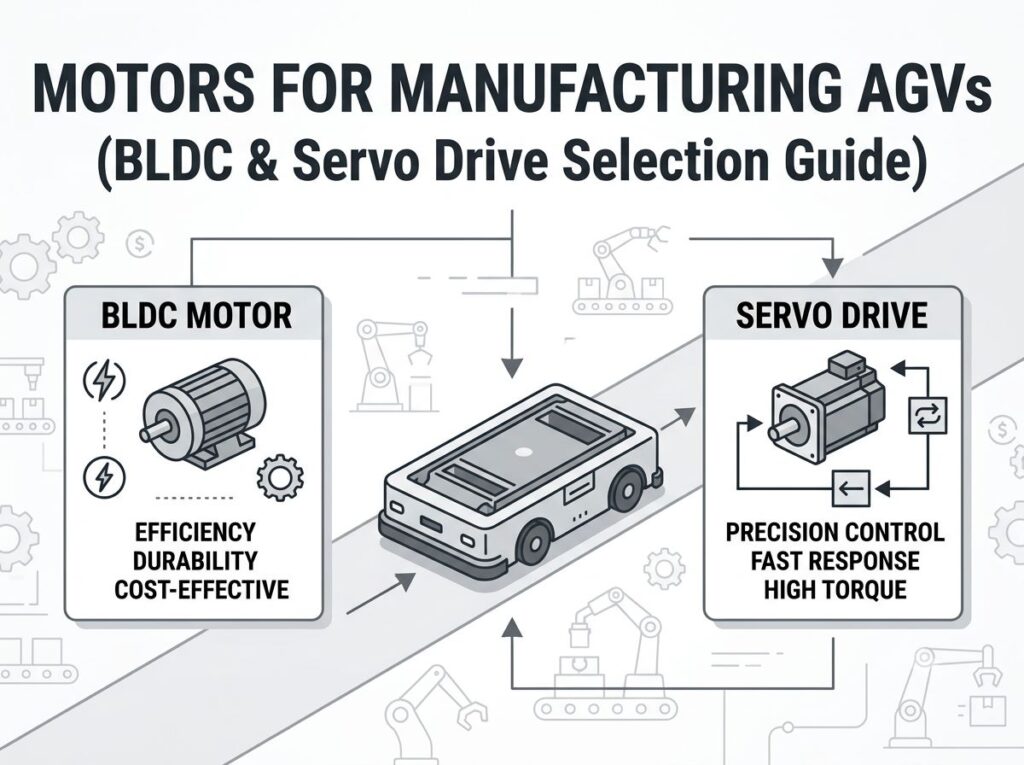
Motors for Manufacturing AGVs
Quick Answer: Manufacturing AGVs are almost always driven by brushless DC (BLDC) motors with Hall sensors, paired with a planetary gearbox, encoder and brake. What makes the factory case special is line-integrated, stop-and-go reliability, not peak torque: the motor must survive IEC 60034-1 S3/S4 start-stop duty or S6/S7 continuous-with-variation duty, hit a high MTBF under coolant, steel dust and 16–24 h daily operation, and stay within insulation class F/H. Match the topology to the job—geared BLDC hub/servo for 0.5–10 t tuggers and unit-load carriers, multi-axle AC/BLDC servo for 10–100+ t assembly platforms—and rate the winding for the real RMS duty, not the catalogue peak.
[ez-toc]
What Are Manufacturing AGVs?
A manufacturing AGV is a battery-powered, guided or autonomous vehicle that moves parts, sub-assemblies, dies and pallets between production cells, warehouses and docks inside a factory. “Motors for manufacturing AGVs” therefore covers the full traction assembly—motor, controller, gearbox, encoder/feedback and brake—because on a production line these are validated as one certified, high-availability system where a stoppage costs far more than the vehicle itself.
The defining difference from other AGV classes is the duty profile. Where a warehouse AGV is optimized for throughput and cost, a hospital robot for silence and EMC, and an airport baggage AGV for 24/7 environmental survival, a manufacturing AGV is optimized for tight integration with the production takt. Real plant data backs this up: Riazi, Bengtsson & Lennartson (IEEE T-ASE, 2021) measured an AGV fleet at a Volvo Cars plant in Gothenburg and showed that optimizing cruise velocity and travelled distance alone cut energy consumption by ~38% without hurting makespan—proof that thermal and duty management, not raw power, is the lever on a factory floor.
How the Manufacturing AGV Drive System Works
Regardless of payload, every manufacturing AGV shares the same drive chain. Selecting the motor means walking this chain and assigning the right component at each stage:
Step 1 — Battery supplies the bus
A Li-ion or LiFePO₄ pack delivers a nominal bus voltage (48/72 V for factory tuggers). Because P = V × I, a higher bus voltage means lower current for the same power, reducing cable size and copper loss. A 2 kW tugger at 24 V draws ~83 A (4–6 AWG); at 48 V it draws ~42 A (8–10 AWG) and runs roughly 4× cooler in the harness. See our AGV battery-voltage selection guide for the full derivation.
Step 2 — Controller commutates the motor
For a BLDC motor, the controller switches current from rotor position (Hall sensors for block commutation, or encoder for sinusoidal/FOC). Maxon documents that block commutation shows ~14% torque ripple, while field-oriented control (FOC) delivers about 5% more continuous torque with smoother running—valuable when a feeder starts loaded on a shop-floor ramp. Sensorless schemes exist but hesitate at 0 RPM, which is unacceptable for a loaded start (see our Hall vs sensorless comparison).
Step 3 — Gearbox multiplies torque
A planetary gearbox trades speed for torque at 90–95% efficiency. Wheel torque is T_wheel = T_motor × ratio × η_gear. Geared BLDC hub and axle motors (e.g. 48 V, 750 W–3 kW, 8–60 N·m, IP65, encoder, electromagnetic brake) are the workhorses of factory tuggers and unit-load carriers because the reduction and wheel are one sealed, serviceable unit.
Step 4 — Wheel meets the floor
The driven wheel converts motor torque into tractive force. Output torque at the contact patch must exceed roll/grade/acceleration demand with margin, or the tugger stalls on a 3% aisle grade. This is where the AGV torque calculation turns a payload into a motor spec.
Step 5 — Feedback closes the loop
Encoder + Hall signals let the controller hold speed against a 600 kg load, regenerate on braking, and report temperature/current to the MES/line controller. On a production line, that telemetry feeds predictive maintenance—a stalled feeder halts the cell, so early thermal warnings matter more than in a free-running warehouse.
Motor Topology Comparison
| Topology | Best manufacturing use | Voltage | Typical power | Feedback | Why / why not |
|---|---|---|---|---|---|
| Geared BLDC hub/axle | Tuggers, unit-load carriers, line feeders (0.5–10 t) | 24–48 V | 500 W–3 kW | Hall + encoder + brake | Sealed, compact, high torque density; default choice for most factory AGVs |
| Integrated BLDC servo | Precision docking, lift/tilt, SMT feeders | 48 V | 400 W–2 kW | Encoder (incremental/absolute) | FOC smoothness, ±0.1 mm positioning; pricier than block-commutated BLDC |
| Multi-axle AC/BLDC servo | Assembly platforms, heavy burden carriers (10–100+ t) | 72–80 V | 4–15 kW | 24-bit encoder, CANopen | Required above ~5 t; distributes load, hits S6/S7 duty |
| Frameless flat BLDC | In-wheel or joint integration on compact cells | 24–48 V | 30–260 W | Hall (optional TSX) | Max integration, hollow shaft for cabling; needs custom housing |
| Brushed DC | — | 24 V | <500 W | — | Avoid: brush wear fails the 24/7 MTBF target; only for prototyping |
Engineering Data: Duty Cycles, Efficiency & Torque
IEC 60034-1 duty classes for manufacturing AGVs
Most factory AGVs never run at constant load. IEC 60034-1:2022 defines ten duty types (S1–S10); five govern manufacturing selection. The key consequence: a motor’s continuous torque rating must cover the RMS torque over the full cycle, not the peak.
| IEC class | Thermal behaviour | Manufacturing AGV match | Torque derating |
|---|---|---|---|
| S1 | Reaches steady-state temperature | Continuous conveyor-style line, 24/7 carrier | None — rated = continuous |
| S3 | No full cooling between cycles | Unit-load, GTP, line-loop tugger | By duty % (ed = on-time / cycle) |
| S4 | Starting losses included | Frequent start-stop feeder, forklift AGV | Derate 10–20% vs S1 |
| S6 | Never stops; load varies | Assembly platform (no idle) | By load/unload ratio |
| S7 | Continuous + braking phases | High-speed positioning axis on line | Braking heat must dissipate/regen |
Insulation classes and efficiency
| Insulation class | Max hot-spot (°C) | Avg winding rise (°C) | Typical use |
|---|---|---|---|
| Class B | 130 | 80 | Legacy only |
| Class F | 155 | 105 | Most factory AGV motors |
| Class H | 180 | 125 | Heavy-duty, hot aisles, brake regen |
| Motor type | Efficiency | Life (h) | Positioning | Best manufacturing fit |
|---|---|---|---|---|
| Brushed DC | 60–75% | 2,000–5,000 | ±5–10 mm | Prototyping only |
| BLDC | 85–92% | 10,000–20,000+ | ±0.5–2 mm (enc.) | Warehouse/line tugger |
| BLDC servo | 90–95% | 10,000–20,000+ | ±0.1 mm | Docking, lift, steering |
| AC servo (IE4) | 90–96%+ | 20,000+ | ±0.05 mm | >5 t assembly, heavy lift |
Core drive formulas
Quantity — Formula (symbols):
- Wheel (traction) torque:
T = (m·g·(μ + sinθ) + m·a) · r / (n·η)— m = total mass; μ = rolling resistance; θ = ramp; a = accel.; r = wheel radius; n = driven wheels; η = drivetrain eff. - Vehicle speed:
v = π · D · N / ig— D = wheel Ø; N = motor rpm; ig = gear ratio - Motor power:
P = T · ω = T · 2πN / 60(T in N·m, N in rpm, P in W) - RMS torque (intermittent duty):
T_rms = √[(T₁²·t₁ + T₂²·t₂ + … + Tₙ²·tₙ) / (t₁ + t₂ + … + tₙ)] - Climb force:
F_climb = m · g · sinθ
Worked example — 2,000 kg factory tugger
For a 2,000 kg gross mass on a 3% shop-floor grade at 1 m/s with 0.5 m/s² acceleration, Crr = 0.02, wheel radius r = 0.15 m, two driven axles, gearbox η = 0.92:
F = m·g·Crr + m·g·sinθ + m·a = 2000·9.81·0.02 + 2000·9.81·0.03 + 2000·0.5 = 392 + 588 + 1000 = 1,980 N- Total wheel torque
T = F·r = 1,980 · 0.15 = 297 N·m; per axle297 / 2 = 148.5 N·m - Motor torque
T_motor = 148.5 / (30 · 0.92) ≈ 5.4 N·mwith a 30:1 gearbox - Add 1.5× safety factor → a 48 V, 1.5–2 kW BLDC per wheel is the right starting point. Validate against RMS over the real S4 cycle, not this peak.
Manufacturer reference data
- Maxon: IDX 70 drive system — 750 W, IP65, up to 3.46 N·m continuous / 7.27 N·m peak, EPOS4 controller, integrated temperature sensor; EC frameless kits (Ø 43–90 mm, 30–260 W) for in-wheel integration; block commutation 14% ripple vs FOC +5% continuous torque.
- FAULHABER: BP4 (Ø 22–32 mm, 12–48 V, up to 158 mNm, 91% η, −40 to +125 °C) and BX4 (Ø 22–32 mm, 24–48 V, 41.8 mNm rated, 78% ηmax) for dynamic start-stop automation; BXT flat (Ø 22–42 mm, 6–48 V, up to 100 W, 134 mNm).
- Yaskawa: Sigma-7 AC servo — 50 W–15 kW, 24-bit absolute encoder (16 M pulses/rev), 350% overload 3–5 s, 3.1 kHz speed loop, STO (SIL3/PLe), −5 to 55 °C (60 °C derated), >18 million units in the field.
- Siemens: SIMOTICS SD available consistently in IE4 (up to >96% efficiency) from 2.2 to 1,000 kW, exceeding ErP 2019/1781; system optimization with converters saves up to 60%.
- SKF: Energy Efficient (E2) deep-groove ball bearings cut friction 30–50% vs standard, roughly double grease life, lift motor efficiency directly.
Best Applications by Robot Type
| Manufacturing AGV type | Payload | Topology | Voltage | IEC duty | GreenSky fit |
|---|---|---|---|---|---|
| Tugger (kit/parts train) | 1–10 t towed | Geared BLDC hub ×2 | 48 V | S3 (long loops) | Differential, 2× driven wheels |
| Unit-load carrier | 0.5–5 t | Geared BLDC / BLDC servo | 48 V | S3 / S4 | Tricycle or differential |
| Forklift / stacker | 1–3 t | BLDC + mast servo | 48 V | S4 (frequent start/stop) | Differential + servo lift |
| Line feeder (SMT/cell) | 0.5–2 t | BLDC servo, precise dock | 48 V | S4 (start-stop) | High-resolution encoder |
| Assembly platform | 0.5–20 t | Tricycle / omni BLDC | 48 V | S1 / S6 (continuous) | Moving production line |
| Heavy-duty burden carrier | 10–100+ t | Multi-axle AC/BLDC servo | 72–80 V | S4 / S5 (braking) | 4+ driven axles |
How to Select a Manufacturing AGV Motor
- Define the duty cycle first. Capture on-time / rest / start-count per hour. This single step decides S1 vs S3/S4 vs S6/S7 and the allowable continuous torque.
- Fix the bus voltage. Pick 48 V for ≤5 t, 72–80 V above. Lower current → smaller harness, less I²R heat (see voltage guide).
- Compute required wheel torque. Use
T = (m·g·(μ + sinθ) + m·a) · r / (n·η)with the worst-case grade and acceleration (see torque guide). - Choose gearbox ratio. Target motor rpm in the 2,000–4,000 range for BLDC; 15:1–50:1 for carriers, 30:1–80:1 for heavy tuggers (see gear vs direct).
- Size for RMS, not peak. Take the S3/S4/S6 RMS torque and require the motor’s continuous rating to exceed it at operating ambient. Oversize 1.3–1.5× for line-availability margin.
- Set the insulation and sealing. Class F minimum, H for hot aisles or regen braking; IP65 against coolant and steel dust.
- Specify feedback and safety. Hall + encoder + brake as standard; integrated temperature sensor with controller trip; STO on servo lifts.
- Plan reliability. High MTBF drive, SKF E2 bearings, CANopen/EtherCAT telemetry for predictive maintenance—because a stalled feeder stops the cell.
Common Engineering Mistakes
| # | Mistake | Consequence | Fix |
|---|---|---|---|
| 1 | Sizing motor from peak torque only | Winding overheats under real RMS cycle | Compute T_rms over S3/S4/S6 and size to it |
| 2 | Specifying S1 motor for S4 line feeder | Chronic insulation failure | Match duty class to application table |
| 3 | Underestimating start/stop heat | Premature bearing and winding wear | Derate 10–20% for S4 starting losses |
| 4 | Choosing 24 V on a >1 t tugger | Oversized harness, I²R losses | Use 48 V; 72–80 V above 5 t |
| 5 | Skipping brake on slope routes | Rollback on power loss | Specify electromagnetic power-off brake |
| 6 | Standard bearings on 24/7 line | Bearing failure = 40%+ of motor downtime | SKF E2 or sealed-for-life bearings |
| 7 | No temperature telemetry | Thermal faults found too late | Integrated NTC + CANopen warning |
Troubleshooting Table
| Problem | Likely cause | Solution |
|---|---|---|
| Motor overheats on shift 2 | RMS duty exceeds S1 rating | Re-rate to S4/S6; enlarge frame or improve cooling |
| Stalls on 3% aisle grade | Undersized torque / gearbox | Recalc T with worst-case grade; raise ratio |
| Erratic speed under load | Encoder or Hall signal loss | Check connector, shielding; replace feedback |
| Bearing noise after 6 months | Standard bearing, coolant ingress | Upgrade to SKF E2 sealed bearing, IP65 |
| Excess I²R harness heat | Bus voltage too low | Move to 48/72 V; downsize cable |
| Brake slips on ramp | Brake torque below grade hold | Specify higher holding-torque power-off brake |
| Controller trips at start | Inrush on cold S4 start | Soft-start / current limit; verify S4 rating |
| Premature insulation aging | Ambient >40 °C, class B | Upgrade to class F/H; add forced cooling |
FAQ
What type of motor is used in manufacturing AGVs?
Most manufacturing AGVs use brushless DC (BLDC) motors with Hall sensors for traction, paired with a planetary gearbox, encoder and electromagnetic brake; integrated servo motors are used where precise line docking or heavy lift is required. Tuggers and unit-load carriers (0.5–10 t) run geared BLDC hub/axle motors (48 V, 750 W–3 kW, 8–60 N·m). Assembly-line and heavy-duty burden carriers (10–100+ t) use multi-axle AC or BLDC servo drives with CANopen/EtherCAT control. Sensorless control is avoided on traction because it hesitates under a loaded start.
How is a manufacturing AGV motor duty different from a warehouse AGV?
A warehouse AMR is optimized for throughput and cost; a manufacturing AGV is optimized for line-integrated, 24/7 reliability under stop-and-go load. A line feeder runs IEC 60034-1 S3/S4 (frequent start/stop with starting losses); an assembly platform on a moving production line runs S6/S7 (continuous periodic with load variation and braking). Specifying a simple S1 motor where S4 or S7 applies causes chronic overheating, because the RMS torque over the real cycle exceeds the S1 continuous rating the nameplate implies.
What reliability metrics should a factory AGV motor meet?
Because a stalled line feeder stops the whole production cell, specify a high MTBF drive, IP65 sealing against coolant and steel dust, insulation class F or H (155 / 180 °C), and an integrated temperature sensor with controller trip. Major automotive and electronics plants also demand redundancy and predictive-maintenance telemetry, so choose a motor with a documented field MTBF and CANopen/EtherCAT reporting. SKF Energy Efficient (E2) bearings cut friction 30–50% and roughly double grease life, directly lifting motor uptime.
How do I size a motor for a 2,000 kg manufacturing tugger?
Start from force: F = m·g·Crr + m·g·sinθ + m·a for a 2,000 kg gross mass on a 3% shop-floor grade at 1 m/s with 0.5 m/s² acceleration → roughly 1,980 N total, or about 297 N·m at the wheel (r = 0.15 m) split across two driven axles. With a 30:1 planetary gearbox at 92% efficiency, the motor needs ~5.4 N·m continuous per wheel; add a 1.5× safety factor and you land near a 48 V, 1.5–2 kW BLDC per wheel. Always size for RMS torque over the real cycle, not the peak.
Is 24 V or 48 V better for manufacturing AGVs?
For manufacturing AGVs the bus is almost always 48 V, and 72–80 V on heavy burden carriers above 5 t. Because P = V × I, a higher bus cuts current for the same power, shrinking cable cross-section and copper loss (I²R). A 2 kW tugger at 24 V draws ~83 A (needs 4–6 AWG); at 48 V it draws ~42 A (8–10 AWG) and runs roughly 4× cooler in the harness. 24 V is only used on light SMT-line feeders under 300 kg. See our battery-voltage selection guide for the full derivation.
Which manufacturers publish manufacturing-grade BLDC/servo motor data?
Maxon documents the IDX 70 drive system (750 W, IP65, up to 3.46 N·m continuous / 7.27 N·m peak, EPOS4 controller, integrated temperature sensor) built for tough continuous logistics duty, and EC frameless kits for in-wheel integration. FAULHABER’s BP4 (12–48 V, up to 158 mNm, 91% efficiency, −40 to +125 °C) and BX4 lines target dynamic start-stop automation. Yaskawa’s Sigma-7 servo (24-bit encoder, 350% overload, vibration suppression, >18 million units in the field) is the integrated-servo reference for high-reliability production lines.
Why Choose GreenSky for Manufacturing AGV Motors?
GreenSky Power designs and manufactures BLDC and integrated servo drive systems engineered for line-integrated, 24/7 factory duty—not generic off-the-shelf motors. Our AGV traction packages are built around your real IEC 60034 duty cycle (S1/S3/S4/S6/S7), validated for RMS torque, class F/H insulation and IP65 sealing against coolant and steel dust.
We offer frame sizes from 22 mm to 120 mm, voltages 12–80 V DC, planetary gearboxes to 80:1, Hall + encoder + electromagnetic brake feedback, and CANopen/EtherCAT telemetry for predictive maintenance. Every unit is wound on automated CNC lines with SPC monitoring, fitted with SKF E2 energy-efficient bearings, and backed by IEC/DOE efficiency documentation for U.S. and EU-bound fleets. See our OEM AGV motor manufacturing guide or contact our engineering team to spec a drive for your production line.
References
- IEC 60034-1:2022 — Rotating electrical machines — Part 1: Rating and performance (duty cycles S1–S10). webstore.iec.ch/publication/69764
- IEC 60034-30-1:2014 — Efficiency classes of line-operated AC motors (IE1–IE5). webstore.iec.ch/publication/65469
- NEMA MG 1-2021 — Motors and Generators (Tables 12-11/12-12 efficiency; §12.58 tolerance). nema.org/standards/view/mg-1-2021
- U.S. DOE, 10 CFR Part 431, Subpart B — Energy conservation standards for electric motors (IE3 from 2027, mid-range IE4). ecfr.gov/current/title-10/part-431/subpart-B
- Riazi S., Bengtsson K., Lennartson B. — “Energy Optimization of Large-Scale AGV Systems,” IEEE Trans. Automation Science and Engineering, 2021 (Volvo Cars plant field data, ~38% energy cut). doi.org/10.1109/TASE.2019.2963285
- Maxon — EC frameless and IDX drive-system documentation (block vs FOC commutation, 14% vs +5% torque). maxongroup.com/en/products/brushless-dc-motors
- FAULHABER — BX4 / BP4 / BXT brushless DC motor data (BP4 up to 158 mNm, 91% η; −40 to +125 °C). faulhaber.com/en/products/brushless-dc-motors
- Yaskawa — Sigma-7 AC servo (24-bit encoder, 350% overload, STO SIL3, >18M units). yaskawa.com/products/motion/drives-and-motors/servo/sigma-7
- SKF — Energy Efficient (E2) deep-groove ball bearings (30–50% less friction, ~2× grease life). skf.com/us/products/…/energy-efficient-bearings
- Siemens — SIMOTICS SD in IE4 (up to >96% efficiency), exceeding ErP 2019/1781. press.siemens.com/global/en/node/6164
