
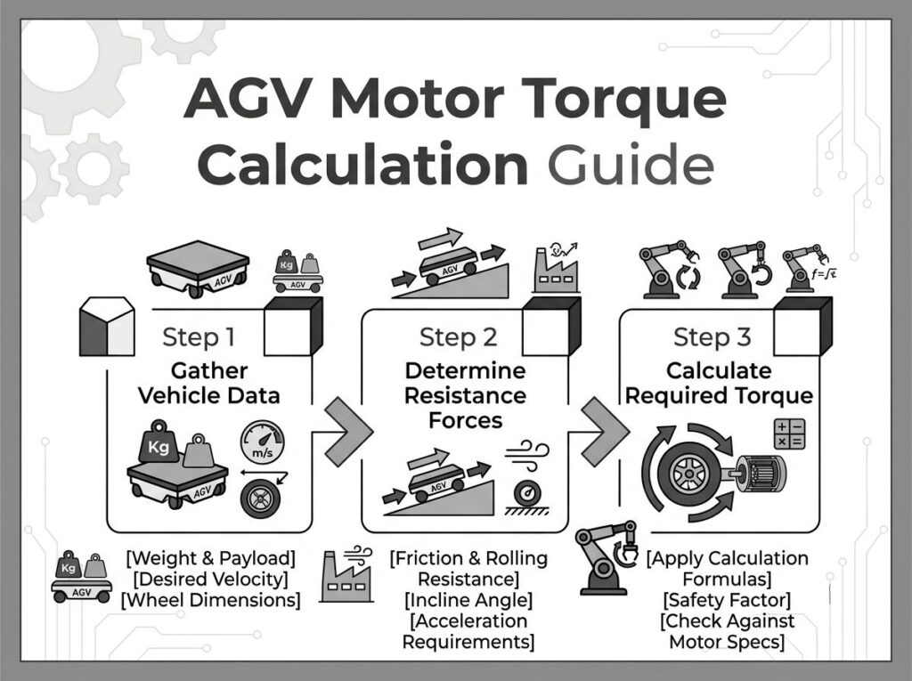
AGV Motor Torque Calculation Guide: Formulas, Worked Examples & Motor Selection
Torque calculation errors are the single most common root cause of AGV drive system failures — overheating under continuous duty, wheel slip during acceleration, and insufficient climbing power on ramps. Many engineering teams select motors based on catalog peak torque or prior project experience, then discover the AGV cannot maintain speed under real-world floor conditions.
This guide provides a complete, standards-referenced methodology for calculating AGV drive motor torque — from the force balance model through gearbox ratio selection, inertia matching, thermal validation, and motor specification by payload class. It follows calculation principles consistent with IEC 60034-1 (rotating electrical machines — rating and performance) and NEMA MG 1 (motors and generators), and references technical documentation from Maxon, Faulhaber, and Yaskawa.
For a broader overview of AGV motor types and selection criteria, see our companion guide: How to Choose a Motor for AGV Applications.
1. Why Torque Calculation Matters
An AGV drive motor does not operate at a single steady-state point. It cycles through acceleration, constant-speed cruising, deceleration, turning, and slope climbing — each imposing a different torque demand on the motor shaft. Selecting a motor by rated torque alone, without mapping the full duty cycle, leads to one of two outcomes:
| Failure Mode | Root Cause | Typical Symptom |
|---|---|---|
| Thermal overload | Continuous torque exceeds motor thermal limit under actual duty cycle (IEC 60034-1 S1 or S5 rating) | Motor winding temperature exceeds insulation class limit; controller trips on thermal protection after 15–30 minutes |
| Torque saturation | Peak torque during acceleration or turning exceeds motor peak/safe operating area | AGV stalls on ramps, wheels slip during launch, positioning overshoot during stop |
| Inertia mismatch | Reflected load inertia exceeds motor rotor inertia by >10:1 (stepper) or >5:1 (servo) | Oscillation during speed transitions, audible buzzing, step loss in open-loop systems |
| Gearbox undersizing | Service factor not applied to gearbox torque rating | Premature gear wear, backlash increase, output bearing failure |
As Yaskawa notes in its servo motor selection white paper, proper sizing requires analyzing the mechanism’s motion profile, calculating the required torque at each phase, and verifying that both continuous (RMS) and peak torque fall within the motor’s safe operating envelope [1]. The same principle applies to BLDC motors used in AGV drive systems.
2. AGV Driving Resistance Model
For industrial AGVs operating at speeds below 2 m/s, aerodynamic drag is negligible. The total driving force must overcome three primary resistances, plus a fourth condition (turning) that applies to differential-drive configurations [2][3].
The fundamental force balance is:
Ftotal = Froll + Fgrade + Facc
Only when the motor-driven traction force equals or exceeds Ftotal can the AGV maintain stable motion.
2.1 Rolling Resistance (Froll)
Rolling resistance arises from elastic deformation between the wheel and the floor surface. It is the dominant resistance during constant-speed operation on flat ground.
Froll = m × g × Crr × cos(θ)
| Parameter | Symbol | Unit | Description |
|---|---|---|---|
| Vehicle mass (gross) | m | kg | AGV chassis + payload + safety margin |
| Gravitational acceleration | g | 9.81 m/s² | Standard gravity |
| Rolling resistance coefficient | Crr | dimensionless | Dependent on wheel material and floor type (see Table in Section 8) |
| Slope angle | θ | rad or deg | Maximum ramp angle on the travel path |
On flat ground (θ = 0), cos(θ) = 1, simplifying the expression to Froll = m × g × Crr.
2.2 Slope / Grade Resistance (Fgrade)
When the AGV climbs a ramp, gravity produces a component along the incline that opposes forward motion.
Fgrade = m × g × sin(θ)
For small angles commonly found in warehouses (2–5% grade), the approximation sin(θ) ≈ tan(θ) ≈ grade ratio is acceptable. For a 3% grade:
Fgrade ≈ m × 9.81 × 0.03 = 0.294 × m (N per kg of vehicle mass)
For a 500 kg AGV on a 3% grade: Fgrade ≈ 147 N. This is roughly equal to the rolling resistance on smooth concrete — meaning slope resistance can double the total traction force requirement compared to flat-floor operation.
2.3 Acceleration Inertia Resistance (Facc)
Newton’s second law governs the force required to accelerate the vehicle mass:
Facc = m × a
| AGV Application | Recommended Acceleration | Rationale |
|---|---|---|
| Standard logistics AGV | 0.4–0.6 m/s² | Balances throughput with wheel traction limits |
| Human-robot collaboration (HRC) | 0.2–0.3 m/s² | ISO 3691-4 safety constraint; limits force on human contact |
| Heavy-duty AGV (1,000+ kg) | ≤ 0.2 m/s² | Prevents wheel slip and protects payload from shifting |
| High-speed AMR (goods-to-person) | 0.6–1.0 m/s² | Acceptable in fenced or controlled environments |
2.4 Turning Resistance (Differential Drive)
For differential-drive AGVs (two powered wheels, multiple casters), in-place rotation is typically the most demanding torque condition — often 2 to 5 times higher than straight-line torque [3]. During rotation, caster wheels generate significant steering resistance, and one drive wheel moves forward while the other moves backward.
An engineering approximation of the spin resistance force is:
Fspin = (2 × Froll × √(W² + L²)) / W
Where W is the wheel track (distance between left and right drive wheels) and L is the vehicle length. The resulting torque per wheel:
Tspin = Fspin × (D / 2)
In most real AGV applications, the in-place rotation torque defines the peak motor torque requirement, while straight-line motion defines the continuous torque requirement [3]. This distinction is critical for proper motor selection — see our Motor for AGV: Complete Selection Guide for motor type comparisons.
3. Core Torque Calculation Formulas
Once the total driving force is determined, convert it to wheel-side torque, then to motor-side torque through the gearbox.
3.1 Wheel-Side Torque
Twheel = (Ftotal × r) / ndrive
| Parameter | Symbol | Typical Value |
|---|---|---|
| Total driving force | Ftotal | Calculated from resistance model (N) |
| Loaded wheel radius | r | 0.065–0.150 m (use loaded radius, not nominal) |
| Number of driven wheels | ndrive | 1 (single-drive), 2 (differential), 4 (4WD) |
Engineering note: Always use the loaded wheel radius, not the nominal diameter from the catalog. Polyurethane wheels compress 3–8% under load, reducing the effective radius and increasing the required torque [4].
3.2 Motor-Side Torque (After Gearbox)
Tmotor = Twheel / (i × ηg)
| Gearbox Type | Typical Efficiency (ηg) | Ratio Range | Backlash |
|---|---|---|---|
| Single-stage planetary | 0.94 (94%) | 3:1–10:1 | <5 arc-min |
| Two-stage planetary | 0.88 (88%) | 10:1–80:1 | <7 arc-min |
| Three-stage planetary | 0.82 (82%) | 100:1–200:1 | <10 arc-min |
| Worm gearbox | 0.60–0.70 | 5:1–60:1 | Self-locking (varies) |
| Spur gear (parallel shaft) | 0.90–0.95 | 3:1–50:1 | Varies by quality |
For a detailed comparison of spur vs. planetary gearboxes for AGV applications, see Spur Gear Motor vs Planetary Gear Motor. The choice between gearbox types directly affects both the efficiency term ηg and the reflected inertia calculation.
3.3 Power Verification
Pwheel = Ftotal × v
Pmotor = Pwheel / (ηg × ηmotor)
Where ηmotor for BLDC motors typically ranges from 0.85 to 0.92 at rated load and speed, as documented in Maxon’s motor selection guide [5] and Faulhaber’s DC motor technical information [6]. The motor’s continuous power rating must exceed Pmotor with a 30–50% margin to account for thermal transients and duty cycle variations.
3.4 Speed Calculation
Vm = (v × 60) / (2π × r) × i (motor RPM)
The target motor speed under load should fall within the motor’s peak efficiency range, typically 60–80% of no-load speed for BLDC motors [5][6]. Operating below 1,000 RPM increases cogging torque and torque ripple; operating above 3,500 RPM increases bearing wear and audible noise [4].
4. Worked Example 1: 200 kg AMR (Goods-to-Person)
This example demonstrates torque calculation for a lightweight AMR used in e-commerce fulfillment.
4.1 Input Parameters
| Parameter | Value |
|---|---|
| Total mass (m) | 200 kg (150 kg payload + 50 kg chassis) |
| Target speed (v) | 1.5 m/s |
| Acceleration (a) | 0.5 m/s² |
| Wheel diameter | 200 mm (r = 0.10 m loaded) |
| Rolling resistance coefficient (Crr) | 0.015 (PU wheel on smooth concrete) |
| Slope | 0° (flat floor) |
| Driven wheels (n) | 2 (differential drive) |
| Safety factor | 1.5× |
4.2 Step-by-Step Calculation
| Step | Formula | Result |
|---|---|---|
| 1. Rolling force | Froll = 200 × 9.81 × 0.015 × cos(0) | 29.4 N |
| 2. Grade force | Fgrade = 200 × 9.81 × sin(0) | 0 N |
| 3. Acceleration force | Facc = 200 × 0.5 | 100 N |
| 4. Total force | Ftotal = 29.4 + 0 + 100 | 129.4 N |
| 5. Wheel torque per wheel | Twheel = (129.4 × 0.10) / 2 | 6.47 N·m |
| 6. Apply safety factor | Twheel,design = 6.47 × 1.5 | 9.71 N·m |
| 7. Motor torque (20:1 planetary, η=0.88) | Tmotor = 9.71 / (20 × 0.88) | 0.55 N·m |
| 8. Wheel RPM at 1.5 m/s | RPM = (1.5 × 60) / (2π × 0.10) | 143 RPM |
| 9. Motor RPM | RPMmotor = 143 × 20 | 2,860 RPM |
| 10. Continuous power per wheel | P = (9.71 × 15.0) / (0.88 × 0.88) | 187.7 W → select 100W BLDC per wheel with 1.5× thermal margin |
Recommended system: 2 × 24V 100W BLDC motors with 20:1 two-stage planetary gearbox, controlled by dual-channel motor controllers via RS485 Modbus RTU.
5. Worked Example 2: 1,200 kg Heavy AGV (Manufacturing Line)
5.1 Input Parameters
| Parameter | Value |
|---|---|
| Total mass (m) | 1,200 kg (1,000 kg payload + 200 kg chassis) |
| Target speed (v) | 0.5 m/s |
| Acceleration (a) | 0.2 m/s² |
| Wheel diameter | 250 mm (r = 0.125 m loaded) |
| Rolling resistance coefficient (Crr) | 0.020 (PU wheel on industrial concrete) |
| Max slope | 3% grade (θ ≈ 1.72°) |
| Driven wheels (n) | 2 (rear drive) |
| Safety factor | 2.0× |
5.2 Step-by-Step Calculation
| Step | Formula | Result |
|---|---|---|
| 1. Rolling force | Froll = 1200 × 9.81 × 0.020 × cos(1.72°) | 235.3 N |
| 2. Grade force | Fgrade = 1200 × 9.81 × sin(1.72°) | 353.4 N |
| 3. Acceleration force | Facc = 1200 × 0.2 | 240 N |
| 4. Total force | Ftotal = 235.3 + 353.4 + 240 | 828.7 N |
| 5. Wheel torque per wheel | Twheel = (828.7 × 0.125) / 2 | 51.8 N·m |
| 6. Apply safety factor | Twheel,design = 51.8 × 2.0 | 103.6 N·m |
| 7. Motor torque (50:1 planetary, η=0.88) | Tmotor = 103.6 / (50 × 0.88) | 2.36 N·m |
| 8. Wheel RPM at 0.5 m/s | RPM = (0.5 × 60) / (2π × 0.125) | 38.2 RPM |
| 9. Motor RPM | RPMmotor = 38.2 × 50 | 1,910 RPM |
| 10. Continuous power per wheel | P = (103.6 × 4.0) / (0.88 × 0.88) | 535.5 W → select 400W BLDC per wheel with regenerative braking |
Recommended system: 2 × 48V 400W BLDC motors with 50:1 two-stage planetary gearbox, BLD6010-class controllers with regenerative braking enabled. The regenerative braking circuit dissipates back-EMF energy during deceleration of the 1,200 kg mass, protecting the controller from overvoltage trips [4].
6. Inertia Matching and Gear Ratio Selection
Torque is only half the sizing equation. Inertia matching between the load and the motor rotor determines dynamic response quality — how quickly the AGV accelerates, how cleanly it stops, and whether the control loop remains stable.
6.1 Equivalent Load Inertia
The vehicle mass, reflected through the wheel and gearbox, appears as an equivalent rotational inertia at the motor shaft:
Jload = (m / ndrive) × r² / i²
Where i is the gearbox ratio. The gearbox reduces the reflected load inertia by the square of the ratio — a 20:1 gearbox reduces load inertia by a factor of 400. This is why high-ratio planetary gearboxes are so effective at improving motor control stability in AGV applications.
6.2 Inertia Ratio Guidelines
| Motor Type | Recommended Jload/Jrotor Ratio | Consequence of Exceeding |
|---|---|---|
| AC servo (closed-loop) | ≤ 5:1 | Loop tuning difficulty; oscillation during speed transitions; reduced bandwidth |
| BLDC servo (closed-loop with encoder) | ≤ 5:1 to 10:1 | Position overshoot; audible resonance at certain speeds |
| Standard BLDC (Hall sensor commutation) | ≤ 10:1 to 15:1 | Sluggish acceleration response; commutation timing errors under high load step |
| Stepper motor (open-loop) | ≤ 10:1 | Step loss during acceleration; resonance at low speeds; stall under sudden load change |
These ratios are consistent with the servo motor selection guidelines published by Yaskawa [1] and the motor sizing methodology described in Maxon’s motor type selection document [5]. For stepper motor applications in AGVs, see our Servo Motor vs Stepper Motor comparison.
6.3 Gear Ratio Selection Method
The optimal gear ratio satisfies three simultaneous constraints:
- Speed constraint: i = RPMmotor,target / RPMwheel, where RPMmotor,target is 1,500–3,000 RPM (peak efficiency range for most BLDC motors) [5][6]
- Torque constraint: i must be high enough that Tmotor falls within the selected motor’s continuous torque rating
- Inertia constraint: i must be high enough that Jload/Jrotor falls within the recommended ratio
In practice, start with the speed constraint to determine a candidate ratio, then verify torque and inertia constraints. If the inertia ratio is too high, increase the gear ratio or select a motor with higher rotor inertia. For applications requiring high positioning accuracy, a direct-drive motor vs gear motor trade-off analysis may be warranted.
7. Peak vs. Continuous Torque: Thermal Validation
Motor datasheets specify two torque values: peak (maximum) and continuous (rated). The continuous torque is limited by the motor’s thermal capacity — the winding insulation class and the cooling method determine how much heat the motor can dissipate under steady-state operation.
7.1 IEC 60034-1 Duty Cycles
IEC 60034-1 defines ten duty cycle classes (S1 through S10) that specify how a motor’s thermal rating applies to different operating patterns [7]. For AGV applications, the most relevant are:
| Duty Class | Description | AGV Relevance |
|---|---|---|
| S1 (Continuous) | Constant load operation until thermal steady state is reached | Long-distance towing on a fixed route; conveyor-following AGV |
| S2 (Short-time) | Constant load for a specified duration, insufficient to reach thermal steady state | Intermittent heavy-payload transport with long rest periods |
| S3 (Intermittent periodic) | Sequence of identical duty cycles with load and rest periods; no significant heating during start | Goods-to-person AMR with frequent pick/place stops |
| S4 (Intermittent periodic with starting) | Like S3 but starting current significantly affects temperature rise | AGV with frequent full-speed starts from rest (typical warehouse AMR) |
| S5 (Intermittent periodic with braking) | Like S4 but includes electric braking periods | AGV with regenerative braking on every stop cycle (most common real-world profile) |
For S5 duty (the most common AGV profile), the RMS (root-mean-square) torque over the full cycle determines the effective continuous torque requirement:
TRMS = √[(Tacc² × tacc) + (Trun² × trun) + (Tdec² × tdec)] / (tacc + trun + tdec + tstop)
The motor’s continuous (S1) torque rating must exceed TRMS, and the motor’s peak torque rating must exceed the maximum instantaneous torque (typically Tacc or Tspin). Oriental Motor’s AGV sizing tool implements this RMS calculation with configurable acceleration, run, deceleration, and stopping time parameters [8].
7.2 NEMA MG 1 Torque Classifications
NEMA MG 1 classifies motors into four design types based on torque characteristics [9]. While NEMA standards primarily apply to AC induction motors, the torque classification framework is useful for understanding motor behavior:
| NEMA Design | Locked Rotor Torque | Pull-Up Torque | Breakdown Torque | Typical Application |
|---|---|---|---|---|
| Design A | Medium | Medium | High | Fans, blowers (not typical for AGV) |
| Design B | Medium | Medium | Medium | General-purpose; IEC Design N equivalent; most common industrial motor |
| Design C | High | High | Medium | High-starting-torque loads; IEC Design H equivalent; conveyor starts |
| Design D | Very High | Varies | Not specified | High inertia starts; punch presses |
For BLDC and servo motors used in AGVs, the analogous parameters are the peak torque (corresponding to locked rotor or starting torque), the continuous torque (corresponding to rated or breakdown torque), and the torque-speed curve shape. Faulhaber’s technical documentation recommends operating the motor in the range where load torque is less than 50% of the stall torque and speed is higher than 50% of no-load speed for optimal efficiency and lifetime [6].
7.3 Thermal Derating
Motor torque ratings in datasheets are specified at a reference ambient temperature (typically 25°C per Maxon [5] or 40°C per IEC 60034-1 [7]). At higher ambient temperatures, the motor must be derated:
| Ambient Temperature | Available Continuous Torque | Available Continuous Current |
|---|---|---|
| 25°C (catalog reference) | 100% | 100% |
| 40°C | ~90% | ~80% |
| 50°C | ~75% | ~65% |
| 60°C | ~60% | ~50% |
For AGVs operating in environments above 40°C (foundries, steel mills, outdoor summer operations), specify motors with Class F (155°C) or Class H (180°C) insulation to maintain rated torque capacity. Our electric motor testing standards page details how GreenSky validates thermal performance under IEC 60034-1 conditions.
8. Rolling Resistance Coefficient Reference
The rolling resistance coefficient (Crr) has the largest variance of any input parameter — it can vary by a factor of 8× depending on the wheel-floor combination. Using an incorrect value is the most frequent calculation error identified by AGV drive system suppliers [2][3][4].
| Wheel Material | Floor Surface | Crr Range | Notes |
|---|---|---|---|
| Polyurethane (PU) | Smooth epoxy | 0.015–0.025 | Lowest resistance; typical warehouse floor |
| Polyurethane (PU) | Smooth concrete | 0.018–0.025 | Most common AGV floor condition |
| Polyurethane (PU) | Rough concrete with joints | 0.020–0.040 | Joints increase resistance significantly |
| Polyurethane (PU) | Outdoor asphalt | 0.035–0.050 | Weather-dependent; wet surface increases Crr |
| Rubber | Concrete | 0.020–0.030 | Higher grip but higher rolling resistance |
| Steel | Steel rail | 0.001–0.002 | Lowest possible Crr; rail-guided AGV only |
| Nylon | Concrete | 0.025–0.040 | Hard wheel; noisy on uneven floors |
Recommendation: Always measure or calibrate Crr with field data before finalizing the motor selection. The AGV Drive Wheel manufacturer’s torque calculation guide recommends using the upper bound of the range for initial sizing, then validating with a loaded coast-down test on the actual installation floor [2].
9. Common Calculation Mistakes
| # | Mistake | Impact | Correct Practice |
|---|---|---|---|
| 1 | Using nominal wheel diameter instead of loaded radius | Underestimates torque by 3–8% (PU compression) | Measure wheel radius under full payload; subtract compression deflection |
| 2 | Ignoring slope torque because ramps are “short” | AGV stalls on ramp; motor overcurrent trip during climb | Always include the worst-case ramp in the force model, even if it is 2 m long |
| 3 | Selecting motor by peak torque only | Motor overheats after 10–15 min of continuous cycling | Calculate RMS torque over the full duty cycle; verify against S1 or S5 rating |
| 4 | Using the same gearbox efficiency for all gearbox types | 30%+ error in motor torque (worm vs. planetary) | Look up efficiency for the specific gearbox type and stage count |
| 5 | Not applying a safety/service factor | Marginal design fails when floor conditions degrade or payload increases | Apply 1.5–2.0× for industrial AGV; 2.5× for safety-critical (medical, food) |
| 6 | Forgetting to verify wheel adhesion | Wheel slips during acceleration; motor spins freely without moving AGV | Verify μ × Fnormal ≥ Ftraction; add preload spring if necessary |
| 7 | Confusing rolling resistance coefficient with friction coefficient | Fundamentally different parameters; using friction μ as Crr overestimates rolling resistance by 20–50× | Rolling resistance (Crr): ~0.01–0.05. Friction coefficient (μ): ~0.3–0.75. Never interchange. |
10. Motor Selection by Payload Class
Once the torque calculation is complete, map the results to motor specifications by payload class. The table below provides starting-point configurations validated across multiple AGV deployments [4][10].
| Parameter | Light AMR (<100 kg) | Medium AGV (100–500 kg) | Heavy AGV (500–3,000 kg) | Heavy Transport (3,000+ kg) |
|---|---|---|---|---|
| Speed range | 1.5–2.0 m/s | 1.0–1.5 m/s | 0.5–1.0 m/s | 0.3–0.5 m/s |
| Voltage | 24V DC | 24V / 36V DC | 48V DC | 48V DC (dual motor) |
| Motor type | 42mm BLDC | 57–86mm BLDC | 86–115mm BLDC | 2× 86–120mm BLDC servo |
| Power per motor | 100–300W | 300–800W | 1,000–2,000W | 500–3,000W each |
| Gearbox | 2-stage planetary 10:1–25:1 | 2-stage planetary 20:1–50:1 | 2-stage planetary 30:1–80:1 | 2-stage planetary 30:1–80:1 w/ brake |
| Wheel torque (cont.) | 2–8 N·m | 8–30 N·m | 30–120 N·m | 120–500 N·m |
| Motor torque (cont.) | 0.1–0.5 N·m | 0.3–1.5 N·m | 0.5–3.0 N·m | 1.0–5.0 N·m each |
| Controller | 10A, RS485 | 10–25A, RS485/CAN | 25A, CANopen | 2× 25A, dual-motor sync |
| Encoder | Hall sensors | Hall + incremental | 17-bit absolute | 17-bit absolute + multi-turn |
| Brake | Optional | Recommended | Required (holding) | Required (dual-circuit) |
For custom motor configurations outside these standard ranges, GreenSky offers custom electric motor design services with IEC 60034-1 compliant testing. To understand the broader AGV vs AMR platform differences that influence motor selection, see our AGV vs AMR comparison guide.
11. 7-Step Torque Calculation Workflow
The following workflow consolidates the complete calculation process into a repeatable engineering procedure:
| Step | Action | Key Output | Common Error |
|---|---|---|---|
| 1 | Define vehicle parameters: mass, speed, acceleration, max slope, wheel diameter, number of drive wheels | Input parameter sheet | Using nominal wheel diameter instead of loaded radius |
| 2 | Calculate resistance forces: Froll, Fgrade, Facc | Ftotal (N) | Using friction coefficient instead of rolling resistance coefficient |
| 3 | Calculate wheel torque per drive wheel: Twheel = (Ftotal × r) / n | Twheel (N·m) | Not dividing by number of drive wheels |
| 4 | Apply safety factor (1.5–2.5×) to get design torque | Twheel,design (N·m) | Applying safety factor to motor torque instead of wheel torque |
| 5 | Select gearbox ratio from speed constraint; verify torque and inertia constraints | Gear ratio i, gearbox type | Selecting ratio without checking inertia ratio |
| 6 | Calculate motor-side torque: Tmotor = Twheel,design / (i × ηg) | Tmotor (N·m) | Using wrong gearbox efficiency for the selected type |
| 7 | Calculate RMS torque over duty cycle; verify against motor continuous rating; check peak torque against motor peak rating; verify thermal derating at ambient temperature | Motor specification validated | Skipping RMS calculation; not checking thermal derating |
12. Adhesion and Wheel Slip Verification
Torque calculation ensures the motor can produce sufficient force. Adhesion verification ensures the wheel can transmit that force to the floor without slipping. These are independent checks — a motor can generate enough torque to spin the wheel without moving the vehicle.
The adhesion constraint is:
μ × Fnormal ≥ Ftraction
| Surface Condition | Friction Coefficient (μ) | Adhesion Quality |
|---|---|---|
| Dry epoxy floor | 0.75 | Excellent |
| Dry concrete | 0.65 | Good |
| Dry gravel | 0.54 | Adequate |
| Wet concrete | 0.35 | Marginal — reduce acceleration |
| Wet surface (general) | 0.30 | Poor — risk of slip |
| Ice/snow | 0.25 | Unacceptable for AGV operation |
If adhesion is insufficient, options include: increasing the normal force via preload springs, adding driven wheels, or reducing the acceleration target. The required preload force is Fnormal = Ftraction / μ, with a 10–20% fatigue margin on the spring rate [3].
13. Motor Torque Constants and Datasheet Interpretation
Motor manufacturers specify torque in terms of a torque constant (Kt), which relates motor current to output torque. Understanding Kt is essential for translating the calculated motor torque into the controller current setting.
Tmotor = Kt × I
Where Kt is in N·m/A and I is the motor phase current in amperes. Per Maxon’s motor data documentation, Kt has tolerances of up to ±10% and decreases with motor temperature due to magnet weakening [5]. Faulhaber’s technical information similarly notes that the torque constant is specified at 25°C and may vary under operating conditions [6].
| Motor Frame Size | Typical Kt (N·m/A) | Typical Continuous Current (A) | Continuous Torque (N·m) |
|---|---|---|---|
| 42mm BLDC (24V) | 0.025–0.050 | 3–8 | 0.08–0.40 |
| 57mm BLDC (24V/36V) | 0.040–0.090 | 5–15 | 0.20–1.35 |
| 86mm BLDC (48V) | 0.080–0.180 | 8–25 | 0.64–4.50 |
| 115mm BLDC (48V/72V) | 0.150–0.350 | 15–40 | 2.25–14.0 |
For BLDC vs servo motor comparisons in AGV applications — including torque constant differences, control loop bandwidth, and encoder requirements — see our BLDC vs Servo Motors for AGVs analysis.
14. Academic and Standards References
The torque calculation methodology described in this guide is grounded in classical mechanics and validated by multiple academic and industry sources. Key references include:
- IEC 60034-1:2022 — Rotating electrical machines — Part 1: Rating and performance. Defines duty cycle classes (S1–S10), thermal classification, and torque definitions [7].
- NEMA MG 1-2021 — Motors and Generators. Defines NEMA Design A/B/C/D torque classifications and IEC Design N/H equivalencies [9].
- Maxon Motor Type Selection — Technical document covering torque constant, speed-torque curves, and motor sizing methodology for DC and BLDC motors [5].
- Faulhaber DC Motors Technical Information — Technical manual covering coreless DC motor torque-speed characteristics, thermal limits, and operating range recommendations [6].
- Yaskawa SigmaSelect Sizing Software White Paper — Application note describing servo motor selection methodology including mechanism analysis, torque profile calculation, and RMS torque verification [1].
- Motor Parametric Calculations for Robot Locomotion (MDPI, 2022) — Peer-reviewed paper presenting motor-transmission coupling selection methodology for mobile robot drive systems, including dynamic operating range analysis [11].
- How to Model Brushless Electric Motors for the Design of Robotics Applications (arXiv, 2023) — Tutorial describing governing equations for BLDC motor modeling, including torque production, back-EMF, and thermal constraints [12].
- Michigan Technological University — Motor Calculations — Engineering reference document covering torque-speed curve construction from raw data measurements, useful for interpreting AGV motor datasheets [13].
15. FAQ
What is the formula for AGV motor torque?
The core formula is Twheel = (Ftotal × r) / n, where Ftotal = Froll + Fgrade + Facc, r is the loaded wheel radius, and n is the number of driven wheels. Motor-side torque is Tmotor = Twheel / (i × ηg), where i is the gearbox ratio and ηg is the gearbox efficiency.
What safety factor should I use for AGV motor torque?
For standard industrial AGVs, apply 1.5–2.0× to the calculated wheel torque. For safety-critical applications (medical, food processing, human-robot collaboration), use 2.5×. The safety factor accounts for floor condition degradation, payload variation, and long-term mechanical wear [2][4].
How do I calculate RMS torque for an AGV duty cycle?
RMS torque is the root-mean-square of the torque profile over one complete cycle: TRMS = √[Σ(Ti² × ti) / Σti]. Include acceleration, constant-speed, deceleration, and stop phases. The motor’s continuous (S1) torque rating must exceed TRMS. This is consistent with IEC 60034-1 S5 duty cycle analysis [7][8].
What rolling resistance coefficient should I use for AGV calculations?
For polyurethane wheels on smooth concrete (the most common AGV floor), use Crr = 0.018–0.025. For epoxy floors, use 0.015–0.025. For rough concrete with joints, use 0.020–0.040. Always use the upper bound for initial sizing and validate with field measurements [2][3].
What inertia ratio is acceptable for AGV motors?
For closed-loop servo and BLDC servo systems, maintain Jload/Jrotor ≤ 5:1. For standard BLDC with Hall commutation, ≤ 10:1 to 15:1. For open-loop steppers, ≤ 10:1. Higher ratios cause control instability, oscillation, and reduced bandwidth [1][5].
Can I use a motor with higher torque than calculated?
Yes, oversizing by 20–50% is acceptable and provides thermal margin. However, excessive oversizing (>2×) wastes battery energy, increases controller cost, and may cause the motor to operate below its efficient speed range. Verify that the motor still operates at 60–80% of no-load speed under typical load [5][6].
References
- Yaskawa America, Inc., “SigmaSelect Sizing Software: Proper Servo System Selection,” White Paper WP.MTN.13. [Online]. Available: https://www.yaskawa.com/delegate/getAttachment?documentId=WP.MTN.13
- AGV Drive Wheel, “How to Calculate AGV Drive Wheel Torque and Motor Sizing,” Apr. 2026. [Online]. Available: https://agvdrivewheel.com/blog/how-to-calculate-agv-drive-wheel-torque-and-motor-sizing
- Yikong Intelligent Equipment (Bicontrols), “Differential Drive Wheel AGV Motor Sizing Guide: Torque Calculation and Inertia Matching,” Jun. 2026. [Online]. Available: https://en.bicontrols.com/news_detail/104.html
- Shenghe Motor (NBshzl), “AGV Drive System Design — BLDC + Gearbox + Controller Engineering Reference,” Jun. 2026. [Online]. Available: https://www.nbshzl-motor.com/agv-drive-system/
- Maxon Group, “Motor Type Selection,” Technical Document, Aug. 2019. [Online]. Available: https://www.maxongroup.us/medias/sys_master/root/8835096313886/5-Motor-Type-Selection.pdf
- Dr. Fritz Faulhaber GmbH & Co. KG, “DC-Motors Technical Information,” Apr. 2026. [Online]. Available: https://www.faulhaber.com/fileadmin/Import/Media/EN_TI_DC-MOTORS.pdf
- International Electrotechnical Commission, IEC 60034-1:2022 Rotating electrical machines — Part 1: Rating and performance, Geneva, Switzerland: IEC, 2022. [Online]. Available: https://webstore.iec.ch/publication/60796
- Oriental Motor U.S.A. Corp., “AGV — Automatic Guided Vehicle Sizing Tool,” Jun. 2026. [Online]. Available: https://www.orientalmotor.com/motor-sizing/agv-sizing.html
- National Electrical Manufacturers Association, NEMA MG 1-2021: Motors and Generators, Rosslyn, VA: NEMA, 2021. Torque classification reference: https://www.engineeringtoolbox.com/iec-nema-standards-torques-d_741.html
- Yikong Intelligent Equipment (Bicontrols), “AGV Drive System Selection Guide: Dynamic Calculation Method for Drive Wheels, Low Voltage Servo Motors and Servo Drives,” Jul. 2026. [Online]. Available: https://en.bicontrols.com/news_detail/111.html
- C. T. Yen and Y. H. Tsai, “Motor Parametric Calculations for Robot Locomotion,” Engineering Proceedings, vol. 20, no. 1, p. 8, Jul. 2022. [Online]. Available: https://www.mdpi.com/2673-4591/20/1/8
- S. P. N. Singh and C. E. Hubert, “How to Model Brushless Electric Motors for the Design of Robotics Applications,” arXiv preprint arXiv:2310.00080, Oct. 2023. [Online]. Available: https://arxiv.org/pdf/2310.00080
- Michigan Technological University, “Motor Calculations — Constructing Torque-Speed Curves from Raw Data,” Jun. 2003. [Online]. Available: https://pages.mtu.edu/~wjendres/ProductRealization1Course/DC_Motor_Calculations.pdf
Need help calculating torque for your AGV project? Contact GreenSky Power with your vehicle parameters — mass, speed, acceleration, slope, wheel diameter — and our engineering team will return a calculation sheet with recommended motor, gearbox, and controller specifications. Explore our full product catalog or learn more about GreenSky Power.
