
12 Mosfets Sine Wave electric bikes Controller
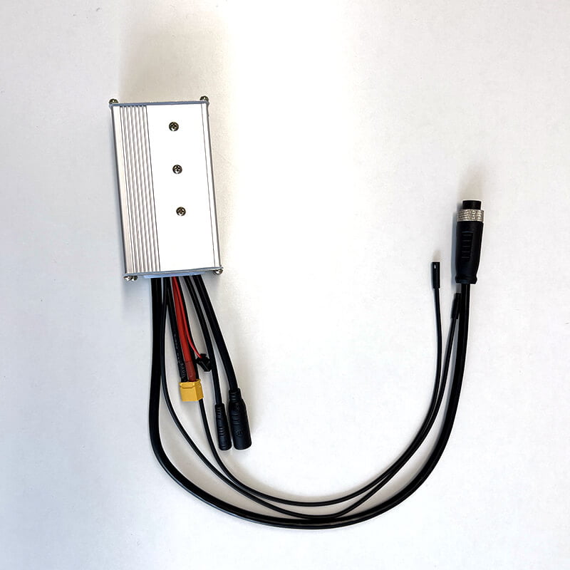
A sinusoidal brushless controller for e-bikes, e-scooters and light electric vehicles, rated 24/36/48 V and 22 A in an extruded aluminium case with a colour-coded harness. Sine wave commutation drives the motor with a smooth rotating field instead of discrete steps, so the drive is quieter and the torque delivery is continuous rather than pulsed. This page also answers the two questions buyers actually ask about a controller of this class: what the twelve MOSFETs change compared with a six-MOSFET board, and what 22 A can really drive at each pack voltage.
A Sine Wave Controller, and What It Changes on the Road
A brushless controller is the power stage between the battery and the motor. It reads the rider’s demand from the throttle, reads rotor position from the Hall sensors, and switches the three motor phases so that the magnetic field rotates in step with the rotor. A sine wave controller does this with a continuously varying voltage on each phase rather than a discrete six-step pattern, which is why the published description calls out smooth starting and low running noise.
The four published characteristics of this unit are below, kept as written and explained next to what each one means in practice.
Circuit protection
The motor runs in a thicker aluminium shell with better heat dissipation, strong climbing ability and low motor running noise — quiet enough that tyre noise is what you hear. The controller’s own case is the same extrusion, so the two share one thermal story.
Outstanding accessories
The drive motor starts more smoothly and the ride is more comfortable, and the single-line instrument increases adaptability by about 80% as published. Treat that figure as the supplier’s own measurement and confirm the instrument model against it.
Sensitive control
As a brushless motor controller it provides stable speed plus sensitive control of braking and direction changes. The wires and interfaces of the harness are what carry that control, so the pinout matters as much as the firmware.
Exquisite craftsmanship
Wires and interfaces are built to stay durable in long use with low malfunction, and every interface carries a different colour for straightforward installation. Colour coding is convenient; the wiring map below is what you should actually wire against.
What Twelve MOSFETs Actually Change
MOSFET count is not a power rating, and it is not a multiplier. It is the number of switching devices in the three-phase bridge. Six means one device per switch position; twelve means two devices in parallel per position. Understanding that distinction is the difference between reading a specification and being sold one.
| What changes | 6 MOSFET (one per position) | 12 MOSFET (two per position) | What it means for your build |
|---|---|---|---|
| Devices in the bridge | Six, one per high-side and low-side position | Twelve, two paralleled per position | Both are complete three-phase bridges; neither is a downgrade of the other |
| Conduction loss at 22 A | Reference level across the bridge | About half of the six-device figure | At 22 A the saving is a few watts, not tens — do not buy this board expecting an efficiency jump |
| Heat per device | Concentrated in six packages | Spread over twelve packages and more of the case | Lower junction temperature for the same current, so longer life at the same load |
| Sustained current in a hot enclosure | Falls away sooner as ambient rises | Holds longer before derating | This is the real reason to choose twelve, and it matters most in summer or in a closed battery box |
| Published current rating | 22 A on the sibling page | 22 A on this page | Identical as published, which confirms the limit sits outside the silicon |
| Short overload behaviour | Less headroom before thermal protection acts | More headroom, so a climb is less likely to cut power | Felt as fewer thermal cut-outs on a long hill, not as a higher top speed |
| Cost and switching loss | Lower device count, lower gate drive burden | More devices and slightly more gate charge to drive | Twelve is not automatically more efficient at every operating point; it is more thermally robust |
The published specification for this unit and for the six-MOSFET sine wave series carries the same 24/36/48 V, the same 120×82×42 mm case, the same 790 g, the same 22 A and the same HS code; only the device count differs. That is consistent with the account above — the current limit is set outside the bridge — but it also means the difference has to be argued thermally rather than claimed as extra output. If your application needs more than 22 A, ask for a higher-current board rather than assuming more devices will provide it.
What 22 A Can Actually Drive
A current rating only becomes a power figure once a voltage is attached to it. The same 22 A controller is a half-kilowatt unit on a 24 V pack and a one-kilowatt unit on a 48 V pack, and that is before any losses are subtracted.
| Pack voltage | Input ceiling at 22 A | Realistic shaft power |
|---|---|---|
| 24 V | 528 W | Around 400–450 W after controller and motor losses |
| 36 V | 792 W | Around 600–680 W |
| 48 V | 1056 W | Around 820–900 W, and only if the case can shed the heat |
Battery current is the one that matters for the rating
A 22 A rating is normally the battery-side current limit, because that is what the shunt measures and what the pack has to deliver. Phase current in the motor can be higher than battery current at low speed, where the controller is stepping voltage down. Ask which one the 22 A refers to before sizing a pack against it.
Two conversions sit between the pack and the road
The controller converts at its own efficiency and the motor converts again. A 1056 W input ceiling does not mean 1056 W at the wheel: at 88% motor efficiency and a few percent in the controller, the shaft figure lands closer to 0.9 kW, and lower still once the case is heat-soaked.
Matching it to a 1000 W motor
A 1000 W motor at 48 V needs roughly 23.7 A at the battery to make its rated output at 88% efficiency, which is already above 22 A before controller losses. Treat this controller as a 750–800 W continuous unit on 48 V, or as a 1000 W unit only for short peaks — and confirm against the actual motor rather than the label.
The published figure is 22 A with no stated basis. Continuous versus peak, battery side versus phase side, and the ambient it was measured at all change what the number means. We do not invent those conditions here. Send the motor’s rated current at your pack voltage and we will state whether this board holds it continuously or needs the next size up.
The Harness, Wire by Wire
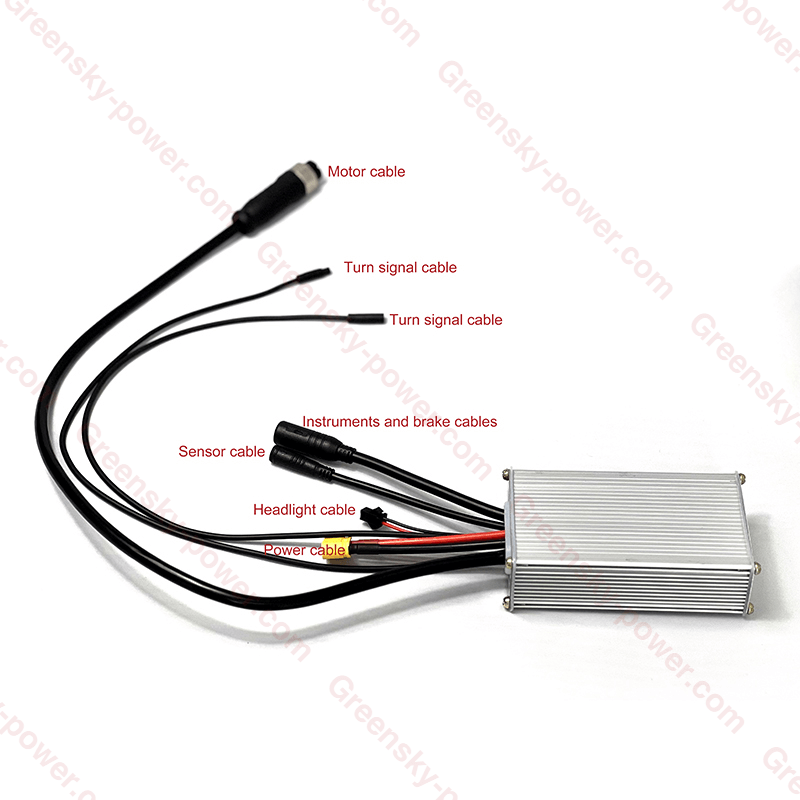
Colour coding helps, but a wiring map is what prevents a mis-connected throttle. This is the harness as supplied, with each lead identified. Confirm pin order on the drawing issued with your order rather than from a photograph.
Speed set 1 – 4.2 V
The published speed-set range is 1–4.2 V, which is the signal span of a conventional 5 V Hall throttle: about 1 V at rest rising to about 4.2 V at full demand, with the ends left as guard bands so the controller can detect a disconnected or shorted throttle. It is a voltage span, not a PWM duty figure, so a PWM throttle or a CAN display will not drive it directly without an interface.
Low-level brake input
A low-level brake input means the brake signal is active when the wire is pulled to ground, which is how most e-bike brake levers with an integrated switch are wired and is also what lets a second brake sensor be added with a simple parallel connection. It also means a broken brake wire may not be detected as a fault, so check continuity as part of any pre-delivery inspection.
The rest of the harness
- Motor cable — three phases plus Hall sensor and temperature leads in one connector
- Sensor cable — Hall supply, ground and three position signals
- Power cable — battery positive and negative with an inline connector
- Instrument and brake cables — display or single-line instrument, plus brake cut-off
- Turn signal and headlight cables — lighting outputs for a road-legal or OEM lighting set
Seal, gasket and cable-jacket materials must be verified against the actual service environment; an outdoor e-bike, a wash-down workshop and a salted winter road do not attack the same compounds. The published specification for this unit does not state an IP rating, so confirm ingress protection on the drawing if the controller is mounted where it will see spray.
Technical Characteristics
Power, current, dimension and weight as published, followed by the interface items still to be confirmed and the documents available today.
| Parameter | Value |
|---|---|
| Voltage | 24 / 36 / 48 V |
| Current | 22 A (basis to confirm — see the rating arithmetic) |
| Tube | 12 mosfet |
| Dimension | 120 mm × 82 mm × 42 mm |
| Weight | 790 g |
| Material | aluminium |
| Speed set | 1 – 4.2 V |
| Brake input | low-level |
| Certification | CE (as published; directive and certificate number to confirm) |
| Warranty | 12 months |
| Trademark | Greensky Power |
| Origin | Zhejiang, China |
| HS Code | 9032899099 |
| Production capacity | 300,000 PCS / month |
| IP rating | Not published — confirm before design freeze |
There is no controller-only specification sheet in the library today, so we do not present a motor datasheet as one. The documents above cover the motor and drive ratings needed to pair this board, and a controller-specific drawing with the pinout and current basis is issued against your motor and pack on request. If a download does not start in a mobile in-app browser, open this page in the system browser and tap again.
Interface — confirm before design freeze
What to ask for · its current status · why it matters on a real build| Item | Status | Why it is on this list |
|---|---|---|
| Basis of the 22 A rating | Not specified — confirm before design freeze | Battery side or phase side, continuous or peak, measured at what ambient. Until that is stated, a pack and a motor cannot be sized against it, and two quotations cannot be compared. |
| Throttle signal definition | 1 – 4.2 V as published; pin and direction to confirm | A Hall throttle, a PWM throttle and a CAN display are three different inputs. Connect the wrong one and the controller either ignores it or runs to full demand. |
| Brake input polarity | Low-level as published; wire colour to confirm | Low-level means short-to-ground to brake. A high-level lever on a low-level input will not cut the motor when the rider expects it to. |
| Hall sensor pin order | Shown on the harness map; sequence to confirm on the drawing | Phase and Hall order must match between motor and controller. Reversing either will not run correctly, and swapping two Hall leads is the usual cause of a motor that stutters. |
| Battery connector and cable gauge | Inline connector as supplied; continuous rating to confirm | A connector rated at 22 A peak is not rated at 22 A continuous. The connector and cable are part of the current limit, not accessories to it. |
| Instrument / display protocol | Not specified — confirm before design freeze | The published single-line instrument compatibility figure depends on which instrument. A different display may need a different firmware or a different harness. |
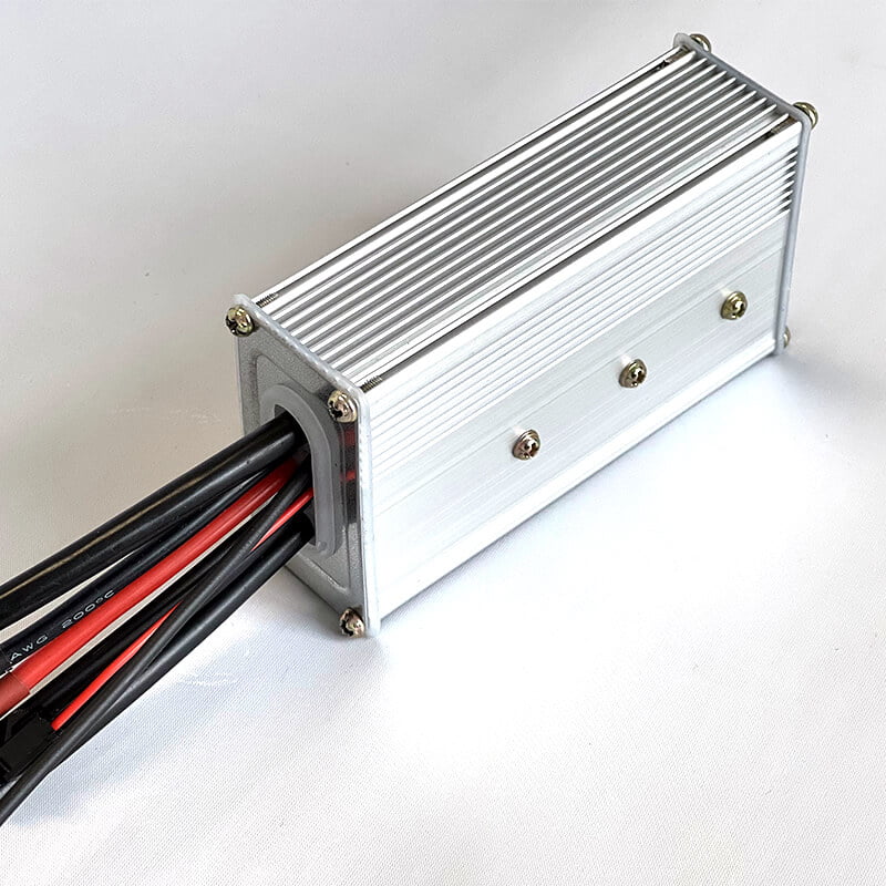
| Ingress protection | Not published — confirm before design freeze | The case is an aluminium extrusion with a gasketed cable exit. That is a good sign, but a sign is not a rating; ask for the IP figure if the controller sees rain or wash-down. |
| Parameter and speed-limit configuration | Not specified — confirm per market | Road-legal speed limits differ by market, and the setting has to be locked or documented per order. This is also the item a customs or market-surveillance check will ask about. |
The Case Is the Heatsink
In a controller of this size there is no fan and no coolant. Heat leaves through the extruded aluminium body, so how and where you mount it decides more about the sustained rating than the MOSFET count does.
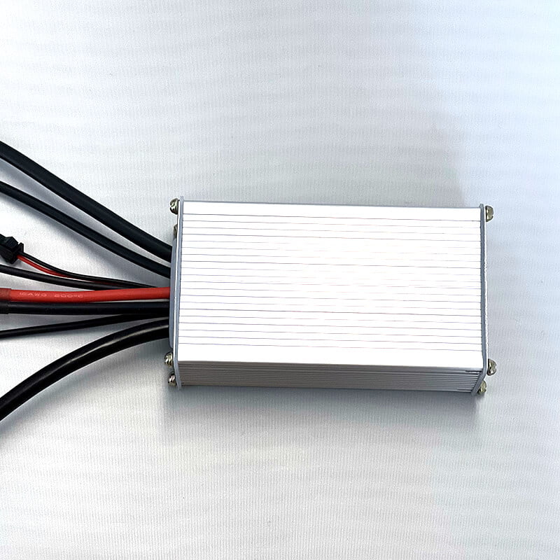
Ribbed extrusion, 120 × 82 × 42 mm
The ribs are the cooling surface: they add area without adding a separate heatsink, and they work best when the fins are vertical so air can move along them by natural convection. Mounted flat against a panel with the fins facing down, most of that area is doing very little.
Three ways to mount it badly
- Inside a closed battery box — the air around it heat-soaks and the rating falls away within the first hour of a ride
- Fins against a panel — the ribbed face is the one that needs air, so it should face out, not be pressed to a flat surface
- Next to the motor or controller of another axis — two heat sources sharing still air raise each other’s ambient
A metal-to-metal path into the frame is worth more than any amount of still air. If the frame is the only structure available, a flat mounting face with thermal compound beats a bracket in free air, provided the frame itself does not sit in sun.
Ambient sets the ceiling
A rating measured on a bench at room temperature is not the rating at 40 °C inside a black enclosure in summer. Ask for the derating curve, or at least the ambient the published 22 A was measured at.
Duty matters more than peak
A commuter bike averaging 8 A but peaking at 22 A on every hill is a different thermal problem from a cargo bike holding 20 A for an hour. Describe the duty, not the maximum.
This is where twelve helps
Spreading the same loss over twice the die area lowers junction temperature at the same case temperature, which extends life and delays thermal roll-back. It is the honest benefit of the twelve-device board.
Where This Controller Fits
The published application range is electric bikes, e-scooters and electric motorcycles, plus robotics and other light electric vehicles. Each one stresses a different part of the specification.
Electric bicycles
24 V and 36 V packs dominate here, where 528–792 W of input ceiling is already generous for a road-legal bike. The throttle span and brake cut-off matter more than the headline current.
E-scooters
Short duty with frequent full-throttle starts. Battery current spikes hard at launch, so the pack and connector take the strain and the controller’s current limit is what protects them.
Electric motorcycles
At 48 V this board is a 750–800 W continuous unit, which suits light urban machines rather than highway use. Sustained current and thermal mounting decide whether it survives.
Robotics and LEV
Where the drive runs at modest current but needs smooth low-speed torque, sinusoidal commutation earns its keep: less cogging, less audible noise, and a gentler start on a geared load.
Whatever the vehicle, the controller is a component and the vehicle is a system. Approval for the finished machine — electrical safety, battery, charger, and the rider’s control of it — belongs to the vehicle manufacturer, not to the component supplier.
Why Choose This Controller
Sinusoidal commutation
A rotating field instead of six discrete steps, which is what makes the start smooth and the running quiet. On a geared hub the difference is audible as well as measurable.
Three pack voltages
One board covers 24, 36 and 48 V, so a product family can move up a voltage class without a new enclosure, a new mounting pattern or a new harness.
Aluminium extrusion body
The case is the heatsink and the structure at once: ribbed for area, screwed for service access, and light enough at 790 g that it does not need its own bracket.
Colour-coded harness
Every interface is a different colour, which shortens assembly and reduces mis-wiring at the dealer end. The wiring map in this page is the reference to wire against.
Lighting and instrument outputs
Turn signal, headlight and instrument leads are part of the harness rather than an add-on, so a complete lighting set can be specified with the drive.
Twelve-device bridge
Thermal headroom at the same rated current, which is the version to specify when the controller lives in a closed box or works in a hot climate.
Customization Options
We provide customized controller and drive solutions based on project requirements. These are the changes that come up most often on an OEM programme.
Voltage and current configuration
Current limit and low-voltage cut-off set for your pack chemistry, so the controller protects the cells you actually use rather than a generic default.
Firmware and parameter set
Assist behaviour, throttle curve, speed limit and roll-back written per market, with the version recorded on the drawing so a later batch matches the approved one.
Harness and connector choice
Connector types, cable lengths and lead outs matched to your frame and battery, which is usually cheaper than adapting a standard harness inside the frame.
Housing and labelling
Case marking, laser or label, your brand and the rating text your market requires, applied in house rather than by a second supplier.
We support
- Prototype development — a working controller on your motor before the harness is tooled
- Small batch production — pilot runs for field trials and certification samples
- Large scale OEM manufacturing — volume build at the published 300,000 PCS per month capacity
Because the motor and the controller are built by the same supplier, the pairing can be validated once rather than twice: current limit, Hall sequence and throttle curve are set against a known motor instead of a specification sheet.
What to send with an RFQ
- Motor rated current, rated speed and Hall arrangement
- Pack nominal voltage, chemistry and maximum discharge current
- Continuous and peak current you need, with the duty cycle
- Throttle type, brake type and instrument or display protocol
- Where the controller mounts, and the ambient it sees
- Market of sale, speed limit and labelling requirements
- Annual volume, sample quantity and target certification
Our Manufacturing Capabilities
Greensky supports OEM and ODM development for BLDC motor and controller application manufacturers.
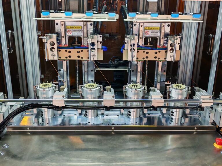
Motor Production Line
Advanced production lines ensure consistent quality and high production capacity for global BLDC motor and controller application manufacturers.
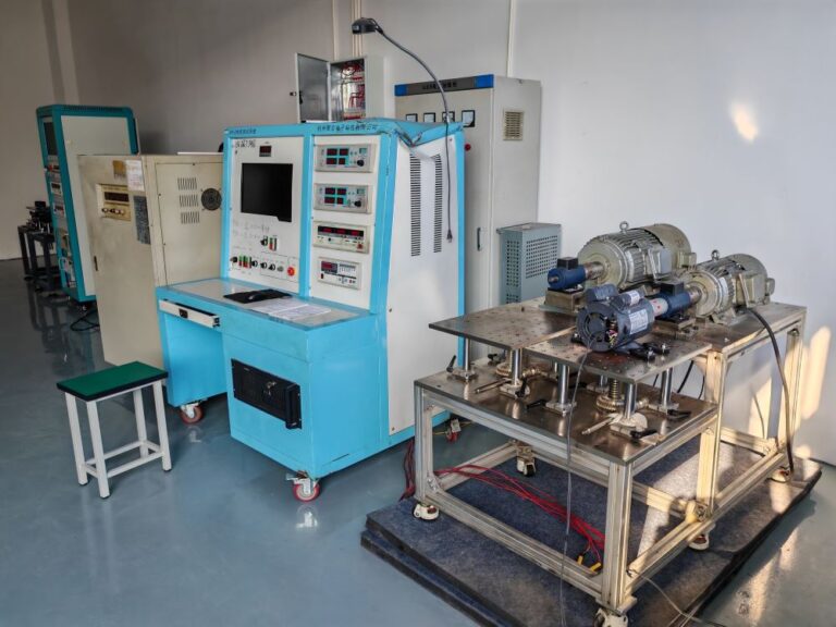
Motor Testing Laboratory
Professional testing equipment verifies torque, efficiency, durability and performance before shipment.
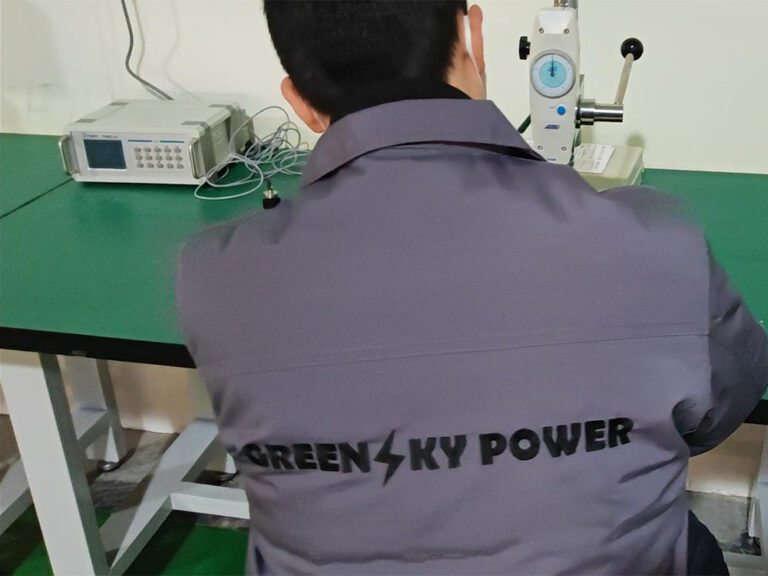
Quality Inspection
Strict inspection procedures ensure each unit meets international standards and customer specifications.

OEM Production
Flexible OEM manufacturing supports custom drive solutions for BLDC motor application manufacturers.
What CE Means for a 24–48 V Controller
The published specification says CE. For a low-voltage DC controller that statement resolves to two directives rather than three, and one of the usual three is genuinely out of scope. Knowing which is which saves a pointless test programme.
EMC applies
Directive 2014/30/EU on electromagnetic compatibility is the directive a switching controller sits under. It covers both what the board emits and its immunity to what the motor and the rest of the vehicle inject. A controller is a noise source and a victim at once, which is why a motor alone can pass and the pair together fail.
RoHS applies
Directive 2011/65/EU restricts six substances in electrical and electronic equipment: lead, mercury, hexavalent chromium, PBB and PBDE at 0.1% by weight in homogeneous material, and cadmium at 0.01%. For a populated board, ask for the report by homogeneous material — solder, plating and cable jacket separately.
The LVD does not apply
The Low Voltage Directive 2014/35/EU covers equipment rated 50–1000 V AC or 75–1500 V DC. A 24, 36 or 48 V DC controller sits below the DC threshold, so it is outside that scope. A supplier who lists the LVD for this product is describing a test they did not need, and that is worth questioning.
For the US market: UL 2849 is a system standard
UL 2849 covers the electrical system of an e-bike: the drive train, the battery, the battery management system, the interconnecting wiring and the power inlet, assessed as a combination. It also states plainly that it does not evaluate the operator’s ability to maintain control while riding. A controller sold as a component cannot carry that certification on its own — the certificate belongs to the vehicle programme.
What we can supply, and what we cannot
- CE documentation as published, with the directive and certificate scope stated
- RoHS material declarations for the board, harness and case
- Test data for the motor and controller pairing at the agreed operating point
- Drawing and parameter sheet for the build, revision controlled
The system-level certification for your finished vehicle is issued by you or by your test house, with our component documents forming part of the technical file. Certificate numbers for this controller are supplied against the specific model and order; we do not print a number here that we cannot tie to a part.
Nothing on this page is a claim that a finished vehicle is legal for road use in any market. Speed limits, power limits and approval routes differ by country and belong to the vehicle manufacturer’s conformity assessment.
Why Choose Greensky
Greensky is a professional electric motor and drive manufacturer specializing in motion control solutions, working with application manufacturers worldwide to develop reliable drive systems. Because the motor and the controller come from the same plant, the pairing is validated once instead of negotiated between two suppliers.
- Strong R&D team — motor, magnetics and drive firmware in house
- Advanced manufacturing equipment — automated winding and board assembly lines
- Strict quality control — incoming, in-process and outgoing inspection on every batch
- OEM customization capability — from a first sample to annual volume
- Global export experience — shipped to more than 50 countries
Related pages on this site
- E-bike controller — how a controller works, and the wider range
- 6 MOSFET sine wave series — the six-device version of this board
- BLDC motor controller — industrial and HVAC range
- 1000W BLDC motor for eBike — a typical motor pairing
Reading the six-device page next is the fastest way to see what the twelve-device board does and does not add, since the published figures are otherwise identical.
Request a Controller Quotation
What to include in your message
- Motor — rated current, rated speed and Hall arrangement, or the model you already use.
- Pack — nominal voltage, chemistry and maximum discharge current.
- Current and duty — continuous and peak current, and the terrain or route the vehicle works on.
- Interface — throttle type, brake type, and the display or instrument you intend to fit.
- Mounting — where the case sits, and the ambient temperature it will see.
- Market and volume — country of sale, speed limit, labelling, sample quantity and annual volume.
Send an inquiry
Send the motor, pack and duty — we reply with a controller proposal within 24 hours.
FAQ – 12 MOSFET Sine Wave Controller
1. Is a 12 MOSFET controller more powerful than a 6 MOSFET one?
Not by itself. MOSFET count is the number of switching devices in the three-phase bridge, not a power rating. Six devices is one per switch position and is already a complete bridge; twelve is two in parallel per position. The published specification for this controller and for the six-MOSFET sine wave series carries the same 22 A, which confirms that the current limit is set by the control board, the shunt, the connector and the cable rather than by silicon. What twelve devices give you is half the conduction loss and half the heat per device at the same current — thermal margin, better overload tolerance and a rating that holds longer in a hot enclosure. If you need more than 22 A, ask for a higher-current board.
2. What can a 22 A controller actually drive?
It depends entirely on pack voltage. At 22 A the input ceiling is about 528 W on 24 V, 792 W on 36 V and 1056 W on 48 V, before losses. Subtract controller and motor losses and the shaft power lands around 400–450 W, 600–680 W and 820–900 W respectively, and the top of each range only holds if the case can shed the heat. For a 1000 W motor at 48 V the motor alone wants about 23.7 A at 88% efficiency, so treat this board as a 750–800 W continuous unit at 48 V or a 1000 W peak unit.
3. Is the 22 A rating battery current or phase current?
The published figure does not say. In most controllers of this architecture the rating refers to battery-side current, because that is what the shunt measures and what the pack has to deliver, while phase current can be higher at low speed where the controller steps voltage down. This matters when you size a pack or a connector, so ask for the basis in writing — battery or phase, continuous or peak, and at what ambient — before freezing the design.
4. What does the 1–4.2 V speed set range mean?
It is the throttle signal span: about 1 V at rest rising to about 4.2 V at full demand, which matches a conventional 5 V Hall throttle with guard bands at each end so the controller can detect a disconnected or shorted input. It is an analogue voltage span, not a PWM duty cycle, so a PWM throttle or a CAN display needs an interface rather than a direct connection.
5. What is a low-level brake input?
The brake signal is active when the wire is pulled to ground, which is how most e-bike brake levers with an integrated switch work and why a second brake sensor can be added in parallel. The trade-off is that a broken brake wire may not register as a fault, since an open circuit looks like “not braking”. Check continuity as part of pre-delivery inspection.
6. Which certifications should this controller carry?
For the EU, a 24–48 V DC controller sits under the EMC Directive 2014/30/EU and the RoHS Directive 2011/65/EU. It is outside the Low Voltage Directive 2014/35/EU, whose DC scope starts at 75 V — so a supplier listing the LVD for this product is describing a test that was not required. For the US market, UL 2849 certifies the electrical system of an e-bike as a combination of drive train, battery, BMS, wiring and power inlet, and explicitly does not evaluate the rider’s control of the vehicle, so it is a vehicle-level certificate rather than a component one.
7. Does the controller have an IP rating?
Not as published. The construction is an aluminium extrusion with a gasketed cable exit, which is what you would expect of a unit intended for outdoor use, but the specification on this page states CE only and does not give an IP figure. If the controller is mounted where it sees rain, spray or wash-down, ask for the IP rating on the drawing — and check the seal at service, because a gland is a mechanical part that ages.
Looking for Sine Wave Controller Solutions?
Contact us for a quotation on the 12 MOSFET sine wave controller, or see the e-bike controller range if your application needs a different current or voltage class. Greensky Power supplies the motor and the drive as one validated pairing — standard models or fully customized OEM solutions.
Professional response guaranteed within 24 hours. Factory Add.: Quanxi Industry Zone, Wuyi, Zhejiang, China · Office Add.: 1509 Binsheng Rd, Hangzhou, Zhejiang, China · E-mail: mkt@greensky-power.com · TEL: +86 571 8819 5488 · Fax: +86 571 8819 4366