
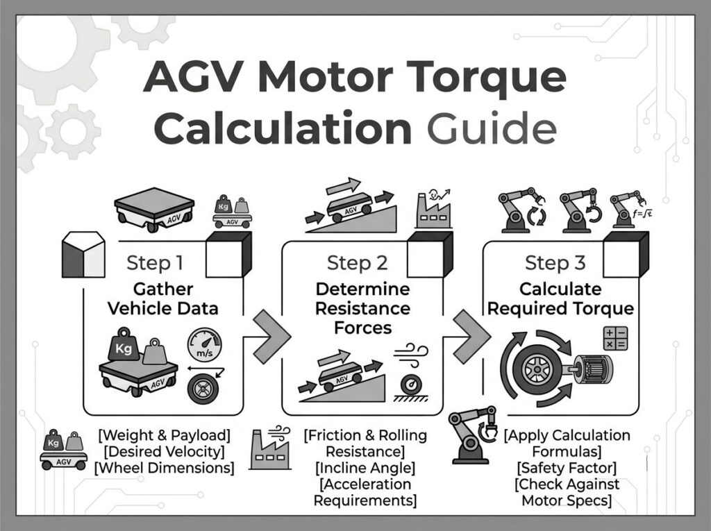
AGV电机扭矩计算指南: 公式, 工作示例 & 电机选型
扭矩计算错误是 AGV 驱动系统故障的最常见根本原因 - 连续工作下过热, 加速时车轮打滑, 坡道上的爬坡能力不足. 许多工程团队根据目录峰值扭矩或之前的项目经验来选择电机, 然后发现 AGV 在现实地面条件下无法保持速度.
本指南提供了完整的, 用于计算 AGV 驱动电机扭矩的标准参考方法 — 从力平衡模型到变速箱传动比选择, 惯性匹配, 热验证, 和按有效负载等级划分的电机规格. 它遵循与以下一致的计算原则 国际电工委员会 60034-1 (旋转电机——额定值和性能) 和 一氧化氮镁 1 (电机和发电机), 以及 Maxon 的参考技术文档, 福尔哈伯, 和安川.
更全面地了解 AGV 电机类型和选择标准, 请参阅我们的配套指南: 如何为 AGV 应用选择电机.
1. 为什么扭矩计算很重要
AGV 驱动电机不在单一稳态点运行. 它通过加速循环, 匀速巡航, 减速, 转动, 和爬坡——每种都对电机轴施加不同的扭矩需求. 仅根据额定扭矩选择电机, 没有映射完整的占空比, 导致两个结果之一:
| 失效模式 | 根本原因 | 典型症状 |
|---|---|---|
| 热过载 | 实际工作周期下连续扭矩超过电机热极限 (国际电工委员会 60034-1 S1 或 S5 等级) | 电机绕组温度超过绝缘等级限制; 15-30 分钟后控制器因热保护而跳闸 |
| 扭矩饱和 | 加速或转弯期间的峰值扭矩超过电机峰值/安全工作区域 | AGV 在坡道上失速, 发射过程中轮子打滑, 停止时定位超调 |
| 惯性不匹配 | 反映的负载惯量超过电机转子惯量 >10:1 (步进器) 或者 >5:1 (伺服) | 速度转换期间的振荡, 听到嗡嗡声, 开环系统中的阶跃损耗 |
| 变速箱尺寸过小 | 使用系数不适用于变速箱扭矩额定值 | 齿轮过早磨损, 反弹增加, 输出轴承故障 |
正如安川在其伺服电机选择白皮书中指出的那样, 适当的尺寸需要分析机构的运动曲线, 计算各相所需扭矩, 并验证两者连续 (有效值) 峰值扭矩落在电机的安全运行范围内 [1]. 同样的原则也适用于 无刷直流电机 用于AGV驱动系统.
2. AGV行驶阻力模型
对于运行速度低于以下速度的工业 AGV 2 多发性硬化症, 空气动力阻力可以忽略不计. 总驱动力必须克服三个主要阻力, 加上第四个条件 (转动) 适用于差动驱动配置 [2][3].
基本的力平衡是:
F全部的 =F卷 + F年级 + FACC
仅当电机驱动牵引力等于或超过F时全部的 AGV能否保持稳定运动.
2.1 滚动阻力 (F卷)
滚动阻力是由车轮与地面之间的弹性变形产生的. 它是平地上恒速运行时的主导电阻.
F卷 =米×克×CRR × 余弦(我)
| 范围 | 象征 | 单元 | 描述 |
|---|---|---|---|
| 车辆质量 (总的) | 米 | 千克 | AGV底盘 + 有效负载 + 安全裕度 |
| 重力加速度 | 克 | 9.81 米/秒² | 标准重力 |
| 滚动阻力系数 | CRR | 无量纲 | 取决于车轮材料和地板类型 (参见章节中的表 8) |
| 倾斜角度 | 我 | 弧度或度 | 行进路径上的最大坡道角度 |
在平坦的地面上 (θ = 0), 因斯(我) = 1, 将表达式简化为 F卷 =米×克×CRR.
2.2 坡 / 等级阻力 (F年级)
当AGV爬坡道时, 重力沿着斜坡产生一个阻碍向前运动的分量.
F年级 = m × g × sin(我)
适用于仓库中常见的小角度 (2–5% 等级), 近似正弦(我) ≈ 棕褐色(我) ≈ 等级比可以接受. 对于一个 3% 年级:
F年级 ≈ 米 × 9.81 × 0.03 = 0.294 × 米 (N/kg 车辆质量)
对于一个 500 kg AGV 上 3% 年级: F年级 ≈ 147 否. 这大致等于光滑混凝土上的滚动阻力,这意味着坡度阻力可以 双倍的 与平地操作相比的总牵引力要求.
2.3 加速惯性阻力 (FACC)
牛顿第二定律规定了加速车辆质量所需的力:
FACC =米×a
| AGV应用 | 推荐加速 | 基本原理 |
|---|---|---|
| 标准物流AGV | 0.4–0.6 m/s² | 平衡吞吐量与车轮牵引力限制 |
| 人机协作 (HRC) | 0.2–0.3 m/s² | 国际标准化组织 3691-4 安全约束; 限制人体接触力 |
| 重型AGV (1,000+ 千克) | ≤ 0.2 米/秒² | 防止车轮打滑并防止有效负载移动 |
| 高速AMR (货到人) | 0.6–1.0 米/秒² | 在围栏或受控环境中可接受 |
2.4 转动阻力 (差动驱动)
适用于差动驱动 AGV (两个动力轮, 多个脚轮), 就地旋转通常是最苛刻的扭矩条件 - 通常 2 至 5 比直线扭矩高几倍 [3]. 旋转期间, 脚轮会产生很大的转向阻力, 一个驱动轮向前移动,另一个驱动轮向后移动.
自旋阻力的工程近似为:
F旋转 = (2 × F卷 × √(W² + L²)) / W
其中W是轮距 (左右驱动轮之间的距离) L 是车辆长度. 每个车轮产生的扭矩:
时间旋转 =F旋转 × (发 / 2)
在大多数实际 AGV 应用中, 就位旋转扭矩定义了 顶峰 电机扭矩要求, 而直线运动定义了 连续的 扭矩要求 [3]. 这种区别对于正确选择电机至关重要 - 请参阅我们的 AGV用电机: 完整的选择指南 用于电机类型比较.
3. 核心扭矩计算公式
一旦总驱动力确定, 将其转换为轮侧扭矩, 然后通过变速箱传递至电机侧扭矩.
3.1 轮边扭矩
时间车轮 = (F全部的 × r) / n驾驶
| 范围 | 象征 | 典型值 |
|---|---|---|
| 总驱动力 | F全部的 | 根据阻力模型计算 (否) |
| 负载轮半径 | r | 0.065–0.150 m (使用加载半径, 不是名义上的) |
| 从动轮数量 | n驾驶 | 1 (单驱动), 2 (微分), 4 (4西数) |
工程笔记: 始终使用 已加载 车轮半径, 不是目录中的标称直径. 聚氨酯轮在负载下压缩 3–8%, 减小有效半径并增加所需扭矩 [4].
3.2 电机侧扭矩 (变速箱后)
时间马达 = T车轮 / (我×n克)
| 变速箱类型 | 典型效率 (或者克) | 比率范围 | 间隙 |
|---|---|---|---|
| 单级行星式 | 0.94 (94%) | 3:1–10:1 | <5 弧分 |
| 两级行星式 | 0.88 (88%) | 10:1–80:1 | <7 弧分 |
| 三级行星式 | 0.82 (82%) | 100:1–200:1 | <10 弧分 |
| 蜗轮变速箱 | 0.60–0.70 | 5:1–60:1 | 自锁式 (各不相同) |
| 正齿轮 (平行轴) | 0.90–0.95 | 3:1–50:1 | 因质量而异 |
有关支线与支线的详细比较. 适用于 AGV 应用的行星齿轮箱, 看 正齿轮电机与行星齿轮电机. 齿轮箱类型的选择直接影响效率项 η克 和反射惯量计算.
3.3 电源验证
P车轮 =F全部的 × v
P马达 =P车轮 / (或者克 × n马达)
其中 η马达 BLDC 电机的范围通常为 0.85 至 0.92 在额定负载和速度下, 如 Maxon 电机选择指南中所述 [5] 和 Faulhaber 的直流电机技术信息 [6]. 电机的连续额定功率必须超过P马达 有 30-50% 的余量来考虑热瞬变和占空比变化.
3.4 速度计算
五米 = (× 60) / (2p×r) × 我 (电机转速)
负载下的目标电机速度应落在电机的峰值效率范围内, BLDC 电机通常为空载速度的 60–80% [5][6]. 下面进行操作 1,000 RPM 增加齿槽转矩和转矩脉动; 上面操作 3,500 RPM 会增加轴承磨损和可闻噪音 [4].
4. 工作示例 1: 200 公斤AMR (货到人)
此示例演示了电子商务履行中使用的轻量级 AMR 的扭矩计算.
4.1 输入参数
| 范围 | 价值 |
|---|---|
| 总质量 (米) | 200 千克 (150 公斤有效负载 + 50 公斤底盘) |
| 目标速度 (v) | 1.5 多发性硬化症 |
| 加速 (一个) | 0.5 米/秒² |
| 轮径 | 200 毫米 (r = 0.10 米加载) |
| 滚动阻力系数 (CRR) | 0.015 (光滑混凝土上的 PU 轮) |
| 坡 | 0° (平地板) |
| 从动轮 (n) | 2 (差动驱动) |
| 安全系数 | 1.5× |
4.2 逐步计算
| 步 | 公式 | 结果 |
|---|---|---|
| 1. 轧制力 | F卷 = 200 × 9.81 × 0.015 × 余弦(0) | 29.4 否 |
| 2. 等级力 | F年级 = 200 × 9.81 × 罪恶(0) | 0 否 |
| 3. 加速力 | FACC = 200 × 0.5 | 100 否 |
| 4. 总力 | F全部的 = 29.4 + 0 + 100 | 129.4 否 |
| 5. 每个车轮的车轮扭矩 | 时间车轮 = (129.4 × 0.10) / 2 | 6.47 牛顿·米 |
| 6. 应用安全系数 | 时间车轮,设计 = 6.47 × 1.5 | 9.71 牛顿·米 |
| 7. 电机扭矩 (20:1 行星的, η=0.88) | 时间马达 = 9.71 / (20 × 0.88) | 0.55 牛顿·米 |
| 8. 车轮转速 1.5 多发性硬化症 | 转速= (1.5 × 60) / (2p × 0.10) | 143 转速 |
| 9. 电机转速 | 转速马达 = 143 × 20 | 2,860 转速 |
| 10. 每轮持续功率 | P= (9.71 × 15.0) / (0.88 × 0.88) | 187.7 W → 选择每轮 100W BLDC,具有 1.5× 热裕度 |
推荐系统: 2 × 24V 100W BLDC 电机 20:1 两级行星式 变速箱, 双通道控制 电机控制器 通过 RS485 Modbus RTU.
5. 工作示例 2: 1,200 公斤重型AGV (生产线)
5.1 输入参数
| 范围 | 价值 |
|---|---|
| 总质量 (米) | 1,200 千克 (1,000 公斤有效负载 + 200 公斤底盘) |
| 目标速度 (v) | 0.5 多发性硬化症 |
| 加速 (一个) | 0.2 米/秒² |
| 轮径 | 250 毫米 (r = 0.125 米加载) |
| 滚动阻力系数 (CRR) | 0.020 (工业混凝土上的 PU 轮) |
| 最大坡度 | 3% 年级 (θ ≈ 1.72°) |
| 从动轮 (n) | 2 (后驱动) |
| 安全系数 | 2.0× |
5.2 逐步计算
| 步 | 公式 | 结果 |
|---|---|---|
| 1. 轧制力 | F卷 = 1200 × 9.81 × 0.020 × 余弦(1.72°) | 235.3 否 |
| 2. 等级力 | F年级 = 1200 × 9.81 × 罪恶(1.72°) | 353.4 否 |
| 3. 加速力 | FACC = 1200 × 0.2 | 240 否 |
| 4. 总力 | F全部的 = 235.3 + 353.4 + 240 | 828.7 否 |
| 5. 每个车轮的车轮扭矩 | 时间车轮 = (828.7 × 0.125) / 2 | 51.8 牛顿·米 |
| 6. 应用安全系数 | 时间车轮,设计 = 51.8 × 2.0 | 103.6 牛顿·米 |
| 7. 电机扭矩 (50:1 行星的, η=0.88) | 时间马达 = 103.6 / (50 × 0.88) | 2.36 牛顿·米 |
| 8. 车轮转速 0.5 多发性硬化症 | 转速= (0.5 × 60) / (2p × 0.125) | 38.2 转速 |
| 9. 电机转速 | 转速马达 = 38.2 × 50 | 1,910 转速 |
| 10. 每轮持续功率 | P= (103.6 × 4.0) / (0.88 × 0.88) | 535.5 W → 选择每轮 400W BLDC,带再生制动 |
推荐系统: 2 × 48V 400W BLDC 电机 50:1 两级行星齿轮箱, 启用再生制动的 BLD6010 级控制器. 再生制动电路在减速期间耗散反电动势能量 1,200 千克质量, 保护控制器免遭过压跳闸 [4].
6. 惯性匹配和齿轮比选择
扭矩只是尺寸方程的一半. 负载和电机转子之间的惯性匹配决定了动态响应质量——AGV 加速的速度, 它停得多么干净, 以及控制回路是否保持稳定.
6.1 等效负载惯量
车辆质量, 通过车轮和变速箱反射, 表现为电机轴上的等效转动惯量:
Ĵ加载 = (米 / n驾驶) × r² / i²
其中 i 是变速箱传动比. 齿轮箱按比率的平方减少反射负载惯量 — a 20:1 变速箱将负载惯量降低了一个系数 400. 这就是为什么高速比行星齿轮箱能够如此有效地提高 AGV 应用中电机控制的稳定性.
6.2 惯性比指南
| 电机类型 | 推荐J加载/Ĵ转子 比率 | 超标的后果 |
|---|---|---|
| 交流伺服 (闭环) | ≤ 5:1 | 环路调整难度; 速度转换期间的振荡; 减少带宽 |
| 无刷直流伺服 (带编码器闭环) | ≤ 5:1 至 10:1 | 位置超调; 在一定速度下可听到共振 |
| 标准无刷直流电机 (霍尔传感器换向) | ≤ 10:1 至 15:1 | 加速反应迟缓; 高负载阶跃下的换向时序误差 |
| 步进电机 (开环) | ≤ 10:1 | 加速时失步; 低速共振; 负载突然变化时失速 |
这些比率与安川发布的伺服电机选择指南一致 [1] 以及 Maxon 电机选型文件中描述的电机选型方法 [5]. 适用于 AGV 中的步进电机应用, 看看我们的 伺服电机与步进电机 比较.
6.3 传动比选择方法
最佳传动比同时满足三个约束:
- 速度限制: 我 = 转速马达,目标 / 转速车轮, 其中转速马达,目标 转速为 1,500–3,000 RPM (大多数 BLDC 电机的峰值效率范围) [5][6]
- 扭矩约束: 我必须足够高以至于T马达 符合所选电机的连续扭矩额定值
- 惯性约束: i 必须足够高 J加载/Ĵ转子 符合推荐比例
在实践中, 从速度约束开始确定候选比率, 然后验证扭矩和惯性约束. 如果惯性比太高, 增大齿轮比或选择转子惯量较大的电机. 适用于定位精度要求高的应用, 一个 直驱电机与齿轮电机对比 权衡分析可能是有道理的.
7. 峰值与. 连续扭矩: 热验证
电机数据表指定了两个扭矩值: 顶峰 (最大限度) 和连续的 (额定). 连续扭矩受到电机热容量的限制——绕组绝缘等级和冷却方法决定了电机在稳态运行下可以散发多少热量.
7.1 国际电工委员会 60034-1 工作周期
国际电工委员会 60034-1 定义十个占空比类别 (S1 至 S10) 指定电机的热额定值如何适用于不同的运行模式 [7]. 适用于 AGV 应用, 最相关的是:
| 职务等级 | 描述 | AGV 相关性 |
|---|---|---|
| S1 (连续的) | 恒定负载运行直至达到热稳定状态 | 固定路线长距离牵引; 输送机跟随式AGV |
| S2 (短时) | 指定持续时间内的恒定负载, 不足以达到热稳态 | 休息时间长的间歇性重载运输 |
| S3 (间歇性周期性) | 具有负载和休息周期的相同工作循环序列; 启动时无明显发热 | 货到人 AMR,频繁取放停靠 |
| S4 (间歇性周期性启动) | 与S3类似,但启动电流显着影响温升 | 频繁从静止全速启动的 AGV (典型仓库AMR) |
| S5 (间歇性周期性制动) | 与 S4 类似,但包括电动制动期 | AGV 在每个停止周期都具有再生制动功能 (最常见的现实世界概况) |
对于 S5 任务 (最常见的 AGV 型材), 均方根值 (均方根) 整个周期的扭矩决定了有效的连续扭矩要求:
时间有效值 = √[(时间ACC² × tACC) + (时间跑步² × t跑步) + (时间十二月² × t十二月)] / (tACC + t跑步 + t十二月 + t停止)
电机连续 (S1) 额定扭矩必须超过 T有效值, 并且电机的峰值扭矩额定值必须超过最大瞬时扭矩 (通常是TACC 或T旋转). 东方电机的 AGV 选型工具通过可配置的加速度实现了 RMS 计算, 跑步, 减速, 和停止时间参数 [8].
7.2 一氧化氮镁 1 扭矩分类
一氧化氮镁 1 根据扭矩特性将电机分为四种设计类型 [9]. 虽然 NEMA 标准主要适用于交流感应电机, 扭矩分类框架有助于理解电机行为:
| NEMA设计 | 堵转扭矩 | 上拉扭矩 | 击穿扭矩 | 典型应用 |
|---|---|---|---|---|
| 设计A | 中等的 | 中等的 | 高的 | 粉丝, 鼓风机 (AGV 不典型) |
| 设计B | 中等的 | 中等的 | 中等的 | 通用型; IEC 设计 N 等效项; 最常见的工业电机 |
| 设计C | 高的 | 高的 | 中等的 | 高启动扭矩负载; IEC 设计 H 等效项; 传送带启动 |
| 设计D | 非常高 | 各不相同 | 未指定 | 高惯量启动; 冲床 |
适用于 AGV 中使用的 BLDC 和伺服电机, 类似的参数是峰值扭矩 (对应于锁定转子或启动扭矩), 连续扭矩 (对应于额定或击穿扭矩), 以及扭矩-速度曲线形状. Faulhaber 的技术文件建议在负载扭矩小于的范围内运行电机 50% 失速扭矩和速度高于 50% 空载速度以获得最佳效率和使用寿命 [6].
7.3 热降额
数据表中的电机额定扭矩是在参考环境温度下指定的 (每个 Maxon 通常为 25°C [5] 或 40°C(根据 IEC) 60034-1 [7]). 在较高环境温度下, 电机必须降额:
| 环境温度 | 可用连续扭矩 | 可用连续电流 |
|---|---|---|
| 25℃ (目录参考) | 100% | 100% |
| 40℃ | 〜90% | 〜80% |
| 50℃ | 〜75% | 〜65% |
| 60℃ | 〜60% | 〜50% |
适用于在 40°C 以上环境中运行的 AGV (铸造厂, 钢厂, 夏季户外作业), 指定 F 级电机 (155℃) 或H级 (180℃) 绝缘以保持额定扭矩能力. 我们的 电动机测试标准 页面详细介绍了 GreenSky 如何根据 IEC 验证热性能 60034-1 状况.
8. 滚动阻力系数参考
滚动阻力系数 (CRR) 具有所有输入参数中最大的方差——根据轮底组合,它可以变化 8 倍. 使用不正确的值是 AGV 驱动系统供应商发现的最常见的计算错误 [2][3][4].
| 轮子材质 | 地板表面 | CRR 范围 | 笔记 |
|---|---|---|---|
| 聚氨酯 (聚氨酯) | 光滑环氧树脂 | 0.015–0.025 | 最低阻力; 典型的仓库地板 |
| 聚氨酯 (聚氨酯) | 光滑混凝土 | 0.018–0.025 | 最常见的 AGV 地面状况 |
| 聚氨酯 (聚氨酯) | 带接缝的粗糙混凝土 | 0.020–0.040 | 关节阻力显着增加 |
| 聚氨酯 (聚氨酯) | 室外沥青 | 0.035–0.050 | 取决于天气; 湿表面增加 CRR |
| 橡皮 | 具体的 | 0.020–0.030 | 抓地力更高但滚动阻力更高 |
| 钢 | 钢轨 | 0.001–0.002 | 尽可能低的CRR; 仅限轨道引导 AGV |
| 尼龙 | 具体的 | 0.025–0.040 | 硬轮; 不平坦的地板上很吵 |
推荐: 始终测量或校准 CRR 在最终确定电机选择之前使用现场数据. AGV 驱动轮制造商的扭矩计算指南建议使用初始尺寸范围的上限, 然后在实际安装地板上进行负载滑行测试进行验证 [2].
9. 常见的计算错误
| # | 错误 | 影响 | 正确的练习 |
|---|---|---|---|
| 1 | 使用标称车轮直径代替负载半径 | 低估扭矩 3–8% (PU压缩) | 测量满负载下的车轮半径; 减去压缩变形 |
| 2 | 忽略斜坡扭矩,因为斜坡是 “短的” | AGV 在坡道上失速; 爬升时电机过流跳闸 | 始终在力模型中包含最坏情况的斜坡, 即使是 2 米长 |
| 3 | 仅根据峰值扭矩选择电机 | 连续循环 10-15 分钟后电机过热 | 计算整个工作周期内的 RMS 扭矩; 验证 S1 或 S5 等级 |
| 4 | 对所有变速箱类型使用相同的变速箱效率 | 30%+ 电机扭矩误差 (蠕虫 vs. 行星的) | 查找特定变速箱类型和级数的效率 |
| 5 | 不应用安全/服务系数 | 当地面条件恶化或有效载荷增加时,边际设计就会失败 | 适用于工业AGV 1.5–2.0×; 2.5× 对于安全至关重要 (医疗的, 食物) |
| 6 | 忘记验证车轮附着力 | 加速时车轮打滑; 电机自由旋转,无需移动 AGV | 验证μ×F普通的 ≥F牵引力; 如有必要,添加预紧弹簧 |
| 7 | 混淆滚动阻力系数与摩擦系数 | 参数根本不同; 使用摩擦力μ作为CRR 高估滚动阻力 20–50 倍 | 滚动阻力 (CRR): ~0.01–0.05. 摩擦系数 (米): 〜0.3–0.75. 切勿互换. |
10. 按有效负载等级选择电机
扭矩计算完成后, 按有效载荷类别将结果映射到电机规格. 下表提供了在多个 AGV 部署中验证的起始配置 [4][10].
| 范围 | 轻型AMR (<100 千克) | 中型AGV (100–500公斤) | 重型AGV (500–3,000 公斤) | 重型运输 (3,000+ 千克) |
|---|---|---|---|---|
| 速度范围 | 1.5–2.0 米/秒 | 1.0–1.5 m/s | 0.5–1.0 米/秒 | 0.3–0.5 m/s |
| 电压 | 24在直流电 | 24五 / 36在直流电 | 48在直流电 | 48在直流电 (双电机) |
| 电机类型 | 42毫米无刷直流电机 | 57–86mm BLDC | 86–115mm BLDC | 2× 86–120mm BLDC 伺服 |
| 每台电机功率 | 100–300W | 300–800W | 1,000–2,000W | 500每个 –3,000W |
| 变速箱 | 2-行星级 10:1–25:1 | 2-行星级 20:1–50:1 | 2-行星级 30:1–80:1 | 2-行星级 30:1–80:1 带刹车 |
| 车轮扭矩 (续) | 2–8牛·米 | 8–30牛·米 | 30–120牛·米 | 120–500牛·米 |
| 电机扭矩 (续) | 0.1–0.5牛·米 | 0.3–1.5牛·米 | 0.5–3.0 牛·米 | 1.0每个 –5.0 N·m |
| 控制器 | 10一个, RS485 | 10-25A, RS485/CAN | 25一个, CANopen | 2×25A, 双电机同步 |
| 编码器 | 霍尔传感器 | 大厅 + 增量式 | 17-有点绝对 | 17-有点绝对 + 多圈 |
| 制动 | 选修的 | 受到推崇的 | 必需的 (保持) | 必需的 (双回路) |
对于这些标准范围之外的定制电机配置, 绿天优惠 定制电动机 IEC 设计服务 60034-1 合规测试. 了解影响电机选择的更广泛的 AGV 与 AMR 平台差异, 看看我们的 AGV 与 AMR 比较指南.
11. 7-步进扭矩计算工作流程
以下工作流程将完整的计算过程整合为可重复的工程程序:
| 步 | 行动 | 关键输出 | 常见错误 |
|---|---|---|---|
| 1 | 定义车辆参数: 大量的, 速度, 加速度, 最大坡度, 轮径, 驱动轮数量 | 输入参数表 | 使用标称车轮直径代替负载半径 |
| 2 | 计算阻力: F卷, F年级, FACC | F全部的 (否) | 用摩擦系数代替滚动阻力系数 |
| 3 | 计算每个驱动轮的车轮扭矩: 时间车轮 = (F全部的 × r) / n | 时间车轮 (牛顿·米) | 不除以驱动轮数量 |
| 4 | 应用安全系数 (1.5–2.5×) 得到设计扭矩 | 时间车轮,设计 (牛顿·米) | 将安全系数应用于电机扭矩而不是车轮扭矩 |
| 5 | 根据速度限制选择变速箱速比; 验证扭矩和惯性约束 | 传动比i, 变速箱类型 | 不检查惯量比而选择比率 |
| 6 | 计算电机侧扭矩: 时间马达 = T车轮,设计 / (我×n克) | 时间马达 (牛顿·米) | 对于所选类型使用了错误的变速箱效率 |
| 7 | 计算占空比内的 RMS 扭矩; 验证电机连续额定值; 检查峰值扭矩与电机峰值额定值; 验证环境温度下的热降额 | 电机规格已验证 | 跳过 RMS 计算; 不检查热降额 |
12. 附着力和车轮打滑验证
扭矩计算确保电机能够 生产 足够的力量. 附着力验证确保车轮可以 发送 施加到地板上的力而不会滑倒. 这些是独立的检查——电机可以产生足够的扭矩来旋转车轮而不移动车辆.
附着力约束为:
米×F普通的 ≥F牵引力
| 表面状况 | 摩擦系数 (米) | 附着力质量 |
|---|---|---|
| 干式环氧地坪 | 0.75 | 出色的 |
| 干混凝土 | 0.65 | 好的 |
| 干碎石 | 0.54 | 足够的 |
| 湿混凝土 | 0.35 | 边际——减少加速度 |
| 湿表面 (一般的) | 0.30 | 差——滑倒的风险 |
| 冰/雪 | 0.25 | AGV 操作不可接受 |
如果附着力不足, 选项包括: 通过预紧弹簧增加法向力, 添加从动轮, 或降低加速目标. 所需预紧力为F普通的 =F牵引力 / 米, 弹簧刚度有 10-20% 的疲劳裕度 [3].
13. 电机扭矩常数和数据表解释
电机制造商以扭矩常数来指定扭矩 (Kt), 它将电机电流与输出扭矩联系起来. 理解Kt 对于将计算出的电机扭矩转换为控制器电流设置至关重要.
时间马达 = Kt × 我
其中 Kt 单位为 N·m/A,I 为电机相电流,单位为安培. 根据 Maxon 的电机数据文档, Kt 公差高达 ±10%,并且由于磁体减弱而随着电机温度的升高而降低 [5]. Faulhaber 的技术信息同样指出,扭矩常数是在 25°C 下指定的,并且在工作条件下可能会有所不同 [6].
| 电机机座尺寸 | 典型 Kt (牛·米/A) | 典型连续电流 (一个) | 连续扭矩 (牛顿·米) |
|---|---|---|---|
| 42毫米无刷直流电机 (24五) | 0.025–0.050 | 3–8 | 0.08–0.40 |
| 57毫米无刷直流电机 (24电压/36V) | 0.040–0.090 | 5–15 | 0.20–1.35 |
| 86毫米无刷直流电机 (48五) | 0.080–0.180 | 8–25 | 0.64–4.50 |
| 115毫米无刷直流电机 (48电压/72V) | 0.150–0.350 | 15–40 | 2.25–14.0 |
AGV 应用中 BLDC 与伺服电机的比较 — 包括扭矩常数差异, 控制环路带宽, 和编码器要求 - 请参阅我们的 AGV 的 BLDC 与伺服电机 分析.
14. 学术和标准参考
本指南中描述的扭矩计算方法以经典力学为基础,并经过多个学术和行业来源的验证. 主要参考文献包括:
- 国际电工委员会 60034-1:2022 — 旋转电机 — 零件 1: 评级和性能. 定义占空比类别 (S1–S10), 热分类, 和扭矩定义 [7].
- 一氧化氮镁 1-2021 — 电动机和发电机. 定义 NEMA 设计 A/B/C/D 扭矩分类和 IEC 设计 N/H 等效值 [9].
- Maxon 电机类型选择 — 涉及扭矩常数的技术文件, 速度-扭矩曲线, 以及直流和 BLDC 电机的电机选型方法 [5].
- Faulhaber 直流电机技术信息 — 涵盖空心杯直流电机扭矩-速度特性的技术手册, 热极限, 和操作范围建议 [6].
- 安川 SigmaSelect 选型软件白皮书 — 描述伺服电机选择方法(包括机构分析)的应用说明, 扭矩曲线计算, 和 RMS 扭矩验证 [1].
- 机器人运动的电机参数计算 (MDPI, 2022) — 同行评审论文介绍了移动机器人驱动系统的电机-传输耦合选择方法, 包括动态工作范围分析 [11].
- 如何为机器人应用设计的无刷电机建模 (arXiv, 2023) — 描述 BLDC 电机建模控制方程的教程, 包括扭矩产生, 反电动势, 和热约束 [12].
- 密歇根理工大学 - 电机计算 — 涵盖根据原始数据测量构建扭矩-速度曲线的工程参考文件, 对于解释 AGV 电机数据表很有用 [13].
15. 常问问题
AGV电机扭矩公式是什么?
核心公式是T车轮 = (F全部的 × r) / n, 其中 F全部的 =F卷 + F年级 + FACC, r 是负载车轮半径, n 是从动轮的数量. 电机侧扭矩为T马达 = T车轮 / (我×n克), 其中 i 是齿轮箱速比,η克 是变速箱效率.
AGV电机扭矩应该采用什么安全系数?
适用于标准工业 AGV, 对计算出的车轮扭矩应用 1.5–2.0×. 适用于安全关键型应用 (医疗的, 食品加工, 人机协作), 使用2.5×. 安全因素导致地板状况恶化, 有效负载变化, 和长期机械磨损 [2][4].
如何计算 AGV 工作周期的 RMS 扭矩?
RMS 扭矩是一个完整周期内扭矩曲线的均方根: 时间有效值 = √[S(时间一世² × t一世) / Σt一世]. 包括加速度, 恒速, 减速, 和停止阶段. 电机连续 (S1) 额定扭矩必须超过 T有效值. 这与IEC一致 60034-1 S5占空比分析 [7][8].
AGV计算时应该使用什么滚动阻力系数?
适用于光滑混凝土上的聚氨酯轮 (最常见的AGV地板), 使用CRR = 0.018–0.025. 适用于环氧地坪, 使用 0.015–0.025. 适用于有接缝的粗糙混凝土, 使用 0.020–0.040. 始终使用上限进行初始尺寸调整并通过现场测量进行验证 [2][3].
AGV电机可接受的惯量比是多少?
适用于闭环伺服和 BLDC 伺服系统, 维持J加载/Ĵ转子 ≤ 5:1. 适用于带霍尔换向的标准 BLDC, ≤ 10:1 至 15:1. 对于开环步进器, ≤ 10:1. 较高的比率会导致控制不稳定, 振荡, 并减少带宽 [1][5].
我可以使用比计算扭矩更高的电机吗?
是的, 尺寸增大 20-50% 是可以接受的,并且可以提供热裕度. 然而, 尺寸过大 (>2×) 浪费电池能量, 增加控制器成本, 并可能导致电机低于其有效速度范围运行. 验证电机在典型负载下仍以 60-80% 的空载速度运行 [5][6].
参考
- 安川美国, 公司, “SigmaSelect 选型软件: 正确的伺服系统选择,” 白皮书 WP.MTN.13. [在线的]. 可用的: https://www.yaskawa.com/delegate/getAttachment?文档ID=WP.MTN.13
- AGV驱动轮, “如何计算 AGV 驱动轮扭矩和电机尺寸,” 四月. 2026. [在线的]. 可用的: https://agvdrivewheel.com/blog/how-to-calculate-agv-drive-wheel-torque-and-motor-sizing
- 一控智能装备 (双控), “差动驱动轮 AGV 电机选型指南: 扭矩计算和惯量匹配,” 君. 2026. [在线的]. 可用的: https://en.bicontrols.com/news_detail/104.html
- 盛和电机 (NBshzl), “AGV驱动系统设计——BLDC + 变速箱 + 控制器工程参考,” 君. 2026. [在线的]. 可用的: https://www.nbshzl-motor.com/agv-drive-system/
- 麦克森集团, “电机选型,” 技术文件, 八月. 2019. [在线的]. 可用的: https://www.maxongroup.us/medias/sys_master/root/8835096313886/5-Motor-Type-Selection.pdf
- 博士. 弗里茨·福尔哈伯有限公司 & 钴. 千克, “直流电机技术信息,” 四月. 2026. [在线的]. 可用的: https://www.faulhaber.com/fileadmin/Import/Media/EN_TI_DC-MOTORS.pdf
- 国际电工委员会, 国际电工委员会 60034-1:2022 旋转电机 - 部分 1: 评级和性能, 日内瓦, 瑞士: 国际电工委员会, 2022. [在线的]. 可用的: https://webstore.iec.ch/publication/60796
- 美国东方汽车. 公司, “AGV:自动引导车辆选型工具,” 君. 2026. [在线的]. 可用的: https://www.orientalmotor.com/motor-sizing/agv-sizing.html
- 全国电气制造商协会, 一氧化氮镁 1-2021: 电机和发电机, 罗斯林, VA: 没有, 2021. 扭矩分类参考: https://www.engineeringtoolbox.com/iec-nema-standards-torques-d_741.html
- 一控智能装备 (双控), “AGV驱动系统选型指南: 驱动轮动态计算方法, 低压伺服电机和伺服驱动器,” 七月. 2026. [在线的]. 可用的: https://en.bicontrols.com/news_detail/111.html
- C. 时间. 日元和Y. H. 蔡, “机器人运动的电机参数计算,” 工程论文集, 卷. 20, 不. 1, p. 8, 七月. 2022. [在线的]. 可用的: https://www.mdpi.com/2673-4591/20/1/8
- S. P. 否. 辛格和C.. 乙. 休伯特, “如何为机器人应用设计的无刷电机建模,” arXiv 预印本 arXiv:2310.00080, 十月. 2023. [在线的]. 可用的: https://arxiv.org/pdf/2310.00080
- 密歇根理工大学, “电机计算 - 根据原始数据构建扭矩-速度曲线,” 君. 2003. [在线的]. 可用的: https://pages.mtu.edu/~wjendres/ProductRealization1Course/DC_Motor_Calculations.pdf
需要帮助计算您的 AGV 项目的扭矩? 联系绿天电力 与您的车辆参数 — 质量, 速度, 加速度, 坡, 车轮直径 - 我们的工程团队将返回包含推荐电机的计算表, 变速箱, 和控制器规格. 探索我们完整的 产品目录 或了解更多 关于绿天电力.