
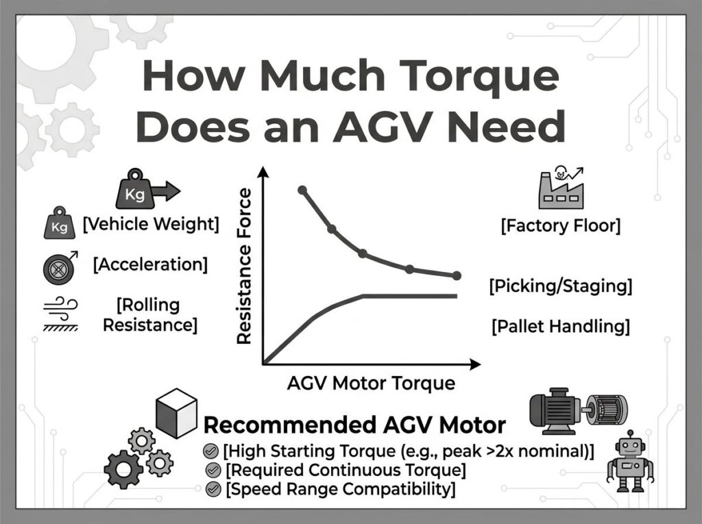
ما هو مقدار عزم الدوران الذي تحتاجه AGV؟? إجابة قائمة على الحمولة مع المعايير الهندسية
Engineers designing Automated Guided Vehicles (AGVs) and Autonomous Mobile Robots (AMRs) routinely ask one question early in the project: how much torque does the drive motor actually need? The answer is never a single number. It depends on vehicle mass, acceleration target, slope angle, wheel diameter, floor friction, number of driven wheels, gearbox ratio, and the thermal duty cycle the motor must sustain. This guide breaks the question down by payload class, provides force-model formulas you can apply immediately, and grounds the recommendations in international motor standards (IEC 60034-1, لا ملغ 1) and manufacturer technical data from Maxon, Faulhaber, and Yaskawa.
Whether you are building a 50 kg indoor AMR or a 60-ton heavy-load transfer cart, the methodology below will get you to a defensible motor torque specification before you issue an RFQ.
Why Torque Sizing Determines AGV Success or Failure
Undersized torque causes motor stall under load, overheating during sustained operation, and failure to climb ramps. Oversized torque wastes battery capacity, increases wheel slip on smooth floors, and raises BOM cost without performance gain. In production environments, AGV reliability is rarely limited by control software — it is limited by the mechanical interaction between motor torque, wheel traction, and floor conditions [1].
The torque requirement is not a single value but a profile across operating conditions. An AGV that moves smoothly on flat epoxy may stall on a 3% ramp. A motor that handles straight-line cruising may fail during in-place rotation, which typically demands two to five times the straight-line torque in differential-drive configurations [5].
| Condition | Torque Too Low | Torque Too High | Correctly Sized |
|---|---|---|---|
| Acceleration from standstill | Stall, motor overheat, navigation timeout | Wheel slip, encoder feedback loss | Smooth launch, stable speed ramp |
| Ramp climbing (3–5% grade) | Vehicle stops on slope, rollback risk | Excess current draw, battery drain | Consistent speed on grade |
| In-place rotation (differential drive) | Cannot complete turn, caster drag | Tire scuffing, floor damage | Predictable turn, minimal wear |
| Sustained operation (8+ ساعات) | Thermal trip, winding insulation degradation | Energy waste, oversized controller cost | Stable temperature within insulation class |
The Quick Answer: Torque by Payload Class
If you need a ballpark before diving into formulas, the table below maps typical AGV payload classes to per-wheel continuous torque, recommended motor type, voltage platform, and gearbox ratio. These values assume 2 driven wheels, polyurethane tires on smooth concrete (Crr = 0.02), 0.5 m/s² acceleration, flat floor, and a safety factor of 1.5. They are starting points, not final specifications — always validate with the force model in the next section.
| Payload Class | Gross Mass (كلغ) | Per-Wheel Continuous Torque (ن · م) | نوع المحرك | الجهد االكهربى | نسبة علبة التروس | Typical Motor Power |
|---|---|---|---|---|---|---|
| Micro AMR (shelf-scanning, inventory) | 30-80 | 0.5–2.0 | BLDC 22–42 mm | 12–24 V DC | 10:1-20:1 | 30–100 W |
| Light AMR (goods-to-person) | 80–200 | 2.0–5.0 | BLDC 42–57 mm | 24 في العاصمة | 15:1–30:1 | 100–300 W |
| Medium AGV (pallet, فرز) | 200-500 | 5.0–15.0 | BLDC 57–86 mm | 24–36 V DC | 20:1-50:1 | 300–800 W |
| Heavy AGV (assembly line, hospital) | 500–3,000 | 15.0–60.0 | BLDC 86–115 mm | 48 في العاصمة | 30:1-80:1 | 800–2,000 W |
| Heavy-load transfer cart (فُولاَذ, foundry) | 3,000–60,000 | 60.0–300.0+ | 2× BLDC 115–120 mm (dual motor) | 48–72 V DC | 30:1-80:1 (with brake gearbox) | 2× 1.5–3 kW |
The torque values in Table 2 are per driven wheel. For a 2-wheel differential drive, the total tractive torque is double the per-wheel value. For a 4-wheel-drive configuration, divide the per-wheel value by 2 (assuming equal load distribution). Always recalculate using the formulas below for your specific operating conditions.
Force Model: Four Resistance Components
AGV drive torque is determined by the total resistance force the vehicle must overcome. The force model decomposes this into four components, each corresponding to a physical resistance source. This decomposition follows the methodology described in the MDPI Engineering Proceedings paper on motor parametric calculations for robot locomotion [9] and is consistent with the sizing approaches used by Oriental Motor [3] and iNetic Motion [4].
1. Rolling Resistance (Froll)
Rolling resistance is the force required to deform the tire and floor at the contact patch. It depends on the tire material, floor surface, and normal load. Polyurethane tires on smooth epoxy have the lowest rolling resistance; rubber tires on rough concrete have the highest.
| Wheel Material | Floor Type | جrr يتراوح | Typical AGV Application |
|---|---|---|---|
| Polyurethane (Shore 92A–95A) | Smooth epoxy | 0.010–0.015 | Cleanroom, electronics factory |
| Polyurethane | Polished concrete | 0.015–0.025 | Warehouse, distribution center |
| Polyurethane | Concrete with joints | 0.020–0.035 | Manufacturing floor |
| Rubber | Epoxy floor | 0.020–0.030 | Hospital, معالجة الغذاء |
| Rubber | Rough concrete / asphalt | 0.035–0.060 | Outdoor transfer path |
| Nylon / Vulkollan | Steel rail / V-track | 0.005–0.010 | Heavy-load rail-guided AGV |
Formula: Froll = m × g × Crr × cos(أنا)
أين م is gross vehicle mass (كلغ), ز = 9.81 m/s², جrr is the rolling resistance coefficient, و أنا is the slope angle. On flat ground, cos(0°) = 1, so the term simplifies to m × g × Crr.
2. Acceleration Force (Facc)
Newton’s second law: the force required to accelerate the vehicle’s mass from rest to target speed. This is typically the largest force component during startup.
Formula: Facc = m × a
أين أ is the target acceleration (m/s²). AGV acceleration is usually 0.3–0.8 m/s² for stability. AMRs may reach 1.0 m/s². Emergency deceleration can require 1.5–2.0 m/s², which produces the highest force transient.
| AGV Type | Normal Acceleration (m/s²) | Emergency Deceleration (m/s²) | ملحوظات |
|---|---|---|---|
| Micro AMR | 0.5–1.0 | 1.5–2.0 | Light payload, rapid start-stop |
| Light AMR (goods-to-person) | 0.4–0.8 | 1.0–1.5 | Balance of speed and load stability |
| Medium AGV (pallet) | 0.3–0.6 | 0.8–1.2 | Prevent pallet shift during braking |
| Heavy AGV (assembly line) | 0.2–0.5 | 0.5–1.0 | Smooth ramp critical for precision loads |
| Heavy-load transfer cart | 0.1–0.3 | 0.3–0.5 | Liquid loads (molten metal) demand ultra-low jerk |
3. Grade Resistance (Fgrade)
When the AGV operates on a ramp — loading dock approaches, floor transitions, or inclined transport paths — gravity adds a component parallel to the slope. This force can be substantial even on modest grades.
Formula: Fgrade = m × g × sin(أنا)
| Slope | Angle (درجات) | Fgrade per 1000 كلغ (ن) | Typical Scenario |
|---|---|---|---|
| 1% | 0.57° | 98 | Floor tolerance, barely perceptible |
| 3% | 1.72° | 294 | Loading dock approach ramp |
| 5% | 2.86° | 490 | Warehouse floor transition |
| 8% | 4.57° | 783 | Parking garage ramp |
| 10% | 5.71° | 977 | Outdoor transfer path, steep grade |
أ 1,200 kg AGV on a 3% ramp must overcome 353 N of grade resistance alone — nearly equal to its rolling resistance on flat ground. If your AGV encounters ramps, grade resistance often becomes the dominant force component.
4. Turning Resistance (Fدور) — Differential Drive Only
In differential-drive AGVs (two powered wheels, multiple casters), in-place rotation generates the highest torque demand. Caster wheels must pivot, creating significant scrub resistance. An engineering approximation from field data [5]:
Formula: Fspin = (2 × Froll × √(W² + L²)) / دبليو
أين دبليو is wheel track width and ل is vehicle length. In practice, rotation torque is 2–5× the straight-line torque, and it usually determines the peak torque rating of the motor.
Core Torque Formulas and Variables
Combining the four force components, the total driving force and wheel torque are calculated as follows. This formulation is consistent with the method described in the MDPI Engineering Proceedings paper [9] and the AGV Drive Wheel sizing guide [2].
Total Driving Force
Ftotal = Froll + Facc + Fgrade
(Turning resistance is evaluated separately as a peak condition, not added to the continuous force.)
Per-Wheel Torque
تwheel = (Ftotal × rwheel) / نيقود
أين صwheel is the loaded wheel radius (not the nominal radius — a polyurethane tire compresses 2–5 mm under load), و نيقود is the number of driven wheels sharing traction.
Motor-Side Continuous Torque
تمحرك = (تwheel × SF) / (i × ηز)
Where SF is the safety factor (1.25–1.5 for indoor, 2.0 for heavy industrial, 2.5 for safety-critical), أنا is the gearbox reduction ratio, و الز is the gearbox efficiency.
| Gearbox Type | Stages | كفاءة (الز) | Typical Ratio Range | رد فعل عنيف |
|---|---|---|---|---|
| كوكبي (دقة) | 1 منصة | 0.94–0.96 | 3:1–10:1 | < 5 arc-min |
| كوكبي (دقة) | 2 stages | 0.88–0.92 | 10:1-50:1 | < 5 arc-min |
| كوكبي (دقة) | 3 stages | 0.82–0.86 | 50:1–200:1 | < 7 arc-min |
| Spur gear (parallel) | 1 منصة | 0.90–0.93 | 2:1–8:1 | 10–30 arc-min |
| Worm gear (الزاوية اليمنى) | 1 منصة | 0.60–0.75 | 5:1-60:1 | لا يوجد (self-locking) |
For AGV applications, two-stage planetary gearboxes are the most common choice because they offer the best balance of efficiency, كثافة عزم الدوران, and backlash. For an in-depth comparison of gearbox types, انظر لدينا spur gear motor vs. محرك التروس الكوكبي تحليل. Worm gearboxes are generally avoided in AGVs due to their low efficiency (which wastes battery capacity) and self-locking behavior (which prevents coasting and regenerative braking).
Power Check
صwheel = Ftotal × v
صمحرك = Pwheel / (الز × ηمحرك)
أين الخامس is target travel speed (آنسة), and ηمحرك is the motor efficiency (0.85–0.92 for BLDC at rated load). This power figure should include a 30–50% margin for surge, braking hold, and ramp startup.
أمثلة عملت: 150 kg AMR and 1,200 kg AGV
مثال 1: 150 kg AMR (Goods-to-Person Robot)
| خطوة | المعلمة | قيمة | Calculation |
|---|---|---|---|
| 1 | Gross mass (م) | 150 كلغ | 100 kg payload + 50 kg chassis |
| 2 | Acceleration (أ) | 0.5 m/s² | Typical for goods-to-person AMR |
| 3 | Slope angle (أنا) | 0° (flat) | Indoor warehouse, no ramps |
| 4 | جrr | 0.015 | PU tire on polished concrete |
| 5 | Loaded wheel radius (ص) | 0.10 م | 200 mm nominal, 5 mm compression |
| 6 | Driven wheels (ن) | 2 | Differential drive |
| 7 | Froll | 22.1 ن | 150 × 9.81 × 0.015 |
| 8 | Facc | 75.0 ن | 150 × 0.5 |
| 9 | Fgrade | 0 ن | Flat ground |
| 10 | Ftotal | 97.1 ن | 22.1 + 75.0 + 0 |
| 11 | تwheel (per wheel) | 4.86 ن · م | (97.1 × 0.10) / 2 |
| 12 | Safety factor applied | 6.55 ن · م | 4.86 × 1.35 (indoor) |
| 13 | Gearbox ratio (أنا) | 20:1 | 2-مرحلة الكواكب |
| 14 | Gearbox efficiency (الز) | 0.90 | 2-مرحلة الكواكب |
| 15 | تمحرك (continuous) | 0.36 ن · م | 6.55 / (20 × 0.90) |
| 16 | Travel speed (الخامس) | 1.5 آنسة | Goods-to-person target |
| 17 | صمحرك (مع 40% margin) | 226 W → select 250 دبليو | (97.1 × 1.5) / (0.90 × 0.88) × 1.4 |
نتيجة: أ 150 kg AMR requires approximately 0.36 N·m continuous motor torque per drive wheel with a 20:1 علبة التروس الكوكبية. أ 24في محرك BLDC in the 200–300 W range with a 42–57 mm frame size is appropriate. ال complete AGV motor selection guide provides additional payload classes and motor model recommendations.
مثال 2: 1,200 kg AGV (Assembly Line Transport)
| خطوة | المعلمة | قيمة | Calculation |
|---|---|---|---|
| 1 | Gross mass (م) | 1,200 كلغ | 1,000 kg payload + 200 kg chassis |
| 2 | Acceleration (أ) | 0.5 m/s² | Smooth launch for assembly parts |
| 3 | Slope angle (أنا) | 1.72° (3% grade) | Loading dock approach |
| 4 | جrr | 0.020 | PU tire on industrial concrete |
| 5 | Loaded wheel radius (ص) | 0.10 م | 200 mm nominal, loaded |
| 6 | Driven wheels (ن) | 2 | Rear differential drive |
| 7 | Froll | 235.4 ن | 1,200 × 9.81 × 0.020 × cos(1.72°) |
| 8 | Facc | 600.0 ن | 1,200 × 0.5 |
| 9 | Fgrade | 353.2 ن | 1,200 × 9.81 × خطيئة(1.72°) |
| 10 | Ftotal | 1,188.6 ن | 235.4 + 600.0 + 353.2 |
| 11 | تwheel (per wheel) | 59.4 ن · م | (1,188.6 × 0.10) / 2 |
| 12 | Safety factor applied | 80.2 ن · م | 59.4 × 1.35 |
| 13 | Gearbox ratio (أنا) | 30:1 | 2-مرحلة الكواكب, الثقيلة |
| 14 | Gearbox efficiency (الز) | 0.88 | 2-مرحلة الكواكب |
| 15 | تمحرك (continuous) | 3.04 ن · م | 80.2 / (30 × 0.88) |
| 16 | Travel speed (الخامس) | 1.0 آنسة | Assembly line pace |
| 17 | صمحرك (مع 50% margin) | 2,144 W → select 2× 1.5 كيلوواط | (1,188.6 × 1.0) / (0.88 × 0.90) × 1.5 |
نتيجة: ال 1,200 kg AGV requires approximately 3.04 N·m continuous motor torque per wheel with a 30:1 ناقل الحركة. A 48V BLDC motor in the 1–2 kW range (86–115 mm frame) is appropriate. Note that the grade resistance (353 ن) contributes 30% of the total force — if the AGV operates only on flat ground, the required torque drops to 2.2 N·m and the power to 1,540 دبليو. This highlights why you must size for the worst-case operating point, not the average.
For a deeper treatment of torque calculation methodology, including differential-drive turning torque and inertia matching, انظر لدينا دليل حساب عزم دوران محرك AGV with full force models and standard references.
Payload-Based Motor Selection Matrix
The table below synthesizes the calculations from the worked examples and extends them across the full payload range. It assumes 2-wheel differential drive, polyurethane tires on smooth concrete, 0.5 m/s² acceleration, and includes both flat-ground and 3% grade scenarios.
| المعلمة | Payload Class | ||||
|---|---|---|---|---|---|
| Micro AMR | Light AMR | Medium AGV | Heavy AGV | Transfer Cart | |
| Gross mass (كلغ) | 50 | 150 | 500 | 1,200 | 5,000 |
| Target speed (آنسة) | 1.5 | 1.5 | 1.0 | 1.0 | 0.5 |
| Ftotal flat (ن) | 32 | 97 | 246 | 835 | 2,453 |
| Ftotal 3% grade (ن) | 81 | 243 | 529 | 1,189 | 3,923 |
| Per-wheel T (flat) (ن · م) | 1.6 | 4.9 | 12.3 | 41.8 | 122.6 |
| Per-wheel T (grade) (ن · م) | 4.1 | 12.2 | 26.5 | 59.4 | 196.2 |
| Safety factor | 1.5 | 1.35 | 1.5 | 1.5 | 2.0 |
| تمحرك cont. (ن · م) | 0.3 | 0.7 | 1.8 | 3.4 | 14.5 |
| قوة المحرك (دبليو) | 50–100 | 200–300 | 500–800 | 1,000–2,000 | 2× 1,500–3,000 |
| Motor frame (مم) | 22–42 | 42–57 | 57–86 | 86–115 | 115–120 (dual) |
| الجهد االكهربى (في العاصمة) | 12–24 | 24 | 24–36 | 48 | 48–72 |
| Gearbox ratio | 10:1-20:1 | 15:1–30:1 | 20:1-50:1 | 30:1-80:1 | 30:1-80:1 |
For custom motor specifications outside these standard payload classes, GreenSky Power offers custom electric motor design with frame sizes from 22 mm to 120 مم, voltage options from 12V to 72V DC, and integrated gearbox solutions.
Thermal Validation: IEC 60034-1 Duty Cycles
Torque alone does not guarantee motor survival. The motor must sustain the required torque within its thermal limits over the actual duty cycle. IEC 60034-1:2022 (طبعة 15, published March 2026) defines ten duty cycle classifications, of which five are most relevant to AGV applications [7].
| فئة اللجنة الانتخابية المستقلة | وصف | Thermal Behavior | AGV Application Match | Torque Derating |
|---|---|---|---|---|
| S1 | Continuous running | Steady-state temperature reached | Conveyor-style AGV, 24/7 line operation | None — rated torque = continuous torque |
| S2 | Short-time duty | Cools to ambient between runs | Batch transport, long idle between moves | Can exceed S1 torque by 1.5–2× for short bursts |
| S3 | Intermittent periodic duty | No significant cooling between cycles | Goods-to-person AMR, cyclic pick-and-place | Depends on duty cycle % (ed = on-time / total cycle) |
| S4 | Intermittent with starting influence | Starting losses included | Frequent start-stop AGV (assembly line feeder) | Starting current heats winding; derate 10–20% vs. S1 |
| S5 | Intermittent with electric braking | Braking energy adds heat | AGV with regenerative braking on ramps | Braking energy must be dissipated or regenerated |
Most AGV applications fall under S3 or S4 duty. The key distinction: if your AGV starts and stops frequently (typical cycle: 10 seconds moving, 20 seconds loading), the motor winding does not fully cool between cycles, and the continuous torque rating must cover the RMS torque over the full cycle, not just the peak.
RMS Torque Calculation
For intermittent duty, calculate the RMS torque over one complete cycle:
تRMS = √[(T₁²×t₁ + T₂²×t₂ + … + تن²×tن) / (t₁ + t₂ + … + رن)]
The motor’s rated continuous torque must exceed TRMS at the operating ambient temperature. If TRMS exceeds the rated torque, the motor will overheat — even if the peak torque is well within the motor’s capability.
Thermal Derating by Ambient Temperature
Motor torque ratings in datasheets are specified at 25°C ambient (per Maxon standard specification 100/101) [11]. At higher ambient temperatures, the permissible continuous torque decreases.
| درجة الحرارة المحيطة | Rated Current (%) | عزم الدوران المقدر (%) | ملحوظات |
|---|---|---|---|
| 25درجة مئوية (catalog baseline) | 100% | 100% | Maxon/Faulhaber catalog values |
| 40درجة مئوية (IEC standard ambient) | 85-90% | 85-90% | Typical industrial environment |
| 50درجة مئوية | 70–75% | 70–75% | Foundry, steel mill, hot warehouse |
| 60درجة مئوية | 50–55% | 50–55% | Extreme environment; upgrade to Class F/H |
If your AGV operates in a 40°C ambient (common in un-air-conditioned warehouses), you must derate the motor by 10–15%. A motor rated for 5 N·m continuous at 25°C delivers only 4.25–4.50 N·m at 40°C. For high-temperature environments, specify Class F (155درجة مئوية) أو الفئة ح (180درجة مئوية) insulation, which allows 100% rated current up to 50°C ambient [12].
لا ملغ 1 Torque Classifications for AGV Motors
لا ملغ 1-2021 classifies motors into four design types based on torque characteristics and starting-load inertia. While NEMA standards are primarily used for AC induction motors, the torque classification framework is useful for understanding motor behavior under AGV startup conditions. IEC Design N and Design H classifications are roughly equivalent to NEMA Design B and C, على التوالى [8].
| NEMA Design | Locked Rotor Torque (% of full-load) | Pull-Up Torque (% of full-load) | Breakdown Torque (% of full-load) | IEC Equivalent | AGV Suitability |
|---|---|---|---|---|---|
| Design A | 100–200% | 100–140% | 200–250% | — | Low starting torque; not ideal for AGV (load may stall on startup) |
| Design B (most common) | 150–200% | 100–140% | 200–250% | IEC Design N | General-purpose; adequate for AGVs with gearbox (gearbox multiplies starting torque) |
| Design C | 200–250% | 140–200% | 190–225% | IEC Design H | عزم دوران عالي عند الانطلاق; suitable for AGVs with heavy payloads and frequent starts |
| Design D | 275%+ | — | لا يوجد (high slip) | — | Highest starting torque; used for heavy-load transfer carts with flywheel effect |
For BLDC motors used in AGVs, the NEMA design classification is less directly applicable because BLDC motors are electronically commutated and their torque-speed curve is determined by the controller, not the rotor design. لكن, the concept of locked-rotor (البدء) torque maps to the BLDC motor’s peak torque rating, which is typically 2–3× the continuous torque rating for 30–60 seconds before thermal protection activates.
The relationship between NEMA torque classifications and BLDC motor selection is discussed in our BLDC motor vs. أجهزة السيارات comparison, which covers how electronic commutation changes the torque-speed envelope.
Peak vs. عزم الدوران المستمر: Why Most Sizing Errors Happen Here
The single most common mistake in AGV motor selection is sizing for peak torque without validating continuous thermal performance. Motor datasheets advertise peak torque prominently because it is the higher number, but peak torque is only available for a limited duration (typically 30–60 seconds) before the winding reaches its thermal limit.
| المعلمة | تعريف | Typical BLDC Ratio (Peak/Continuous) | AGV Sizing Rule |
|---|---|---|---|
| عزم الدوران المستمر (rated) | Torque the motor can deliver indefinitely without exceeding insulation class temperature | 1.0× (baseline) | Must exceed TRMS of the duty cycle |
| Peak torque (الحد الأقصى) | Maximum torque before demagnetization or thermal trip | 2.0–3.0× | Must exceed worst-case transient (تسريع, ramp start, دور) |
| Stall torque | Torque at zero speed (motor held stationary at rated voltage) | 3.0–5.0× | Never operate at stall; causes rapid overheating |
| Torque constant (كر) | Torque per unit current (N·m/A) | — | Use to calculate required current: I = T / كر |
Maxon specifies that motor constants have tolerances of up to ±10% and change with motor temperature — catalog values apply at 25°C, and a warm motor produces less torque [11]. Faulhaber’s DC Motors Technical Information notes that for optimal motor operation, the required speed should be higher than half the no-load speed, and the load torque should be less than the maximum continuous torque [12]. Yaskawa’s SigmaSelect sizing software generates a comparison report between servo system capability and application requirements, explicitly separating peak and continuous operating points [13].
Practical rule: Size the continuous torque to cover the RMS torque of the duty cycle (including derating for ambient temperature), then verify that the peak torque covers the worst-case transient. If the peak/continuous ratio of your selected motor is less than 2.0×, you may need a larger motor even if the continuous torque appears adequate.
Gearbox Matching: Reflected Torque and Inertia
The gearbox does more than reduce speed and multiply torque. It also transforms the load inertia as seen by the motor, which affects control stability and acceleration response.
Reflected Inertia
The load inertia reflected to the motor shaft is divided by the square of the gearbox ratio:
جreflected = Jحمل / i²
أين جحمل is the vehicle inertia at the wheel and أنا is the gearbox ratio. أ 20:1 gearbox reduces the reflected inertia by a factor of 400, making the motor see a much smaller inertia. This is critical for servo-controlled AGVs where the inertia ratio affects tuning stability.
| نوع التحكم | Recommended Jحمل/جمحرك نسبة | Consequence of Exceeding |
|---|---|---|
| مضاعفات (closed-loop, FOC) | < 5:1 | Oscillation, tuning difficulty, audible noise |
| السائر (open-loop) | < 10:1 | Lost steps, resonance at low speeds |
| BLDC with Hall sensors (velocity loop) | < 10:1 | Sluggish response, speed droop under load |
For AGV applications using BLDC motors with Hall-sensor feedback, an inertia ratio below 10:1 is generally acceptable because the velocity control loop does not require the precision of a position loop. For applications requiring precise positioning (على سبيل المثال, AGV docking), consider upgrading to a motor controller with encoder feedback and targeting an inertia ratio below 5:1.
Gearbox Selection for AGV Drives
For AGV drive systems, the gearbox ratio is selected to place the motor’s operating speed in its efficiency sweet spot (typically 1,500–3,000 RPM for BLDC motors). أقل 1,000 دورة في الدقيقة, torque ripple and cogging become noticeable; above 3,500 دورة في الدقيقة, bearing life degrades and noise increases [12].
ملكنا spur vs. planetary gearbox comparison provides a detailed analysis of why planetary gearboxes are preferred for AGV applications — higher torque density, lower backlash, and coaxial output that simplifies wheel-hub integration. For applications requiring right-angle output (على سبيل المثال, steering drives), ملكنا gearbox product page lists NMRV worm gearboxes and bevel-helical options.
Traction Verification: Preventing Wheel Slip
Calculating the required torque is necessary but not sufficient. The torque must be transmissible through the wheel-floor contact. If the applied torque exceeds the friction limit, the wheel slips — and encoder feedback becomes unreliable, directly affecting navigation accuracy [1].
Traction Limit Formula
Ftraction_max = μ × Nيقود
Where μ is the static friction coefficient between wheel and floor, and Nيقود is the normal force on the driven wheel (not the total vehicle weight — only the weight borne by the driven wheels).
| Wheel Material | Floor Material | μ (static) | ملحوظات |
|---|---|---|---|
| Polyurethane (Shore 95A) | Epoxy floor | 0.6 | Standard warehouse combination |
| Polyurethane | Concrete | 0.7 | Manufacturing floor |
| Rubber | Epoxy floor | 0.8 | Higher grip, faster floor wear |
| Rubber | Concrete | 0.9 | Maximum grip, تطبيقات الثقيلة |
| Nylon | Steel rail | 0.3–0.4 | Rail-guided AGV; الاحتكاك المنخفض, requires high normal force |
Verification rule: The per-wheel tractive force (Ftotal / نيقود) must not exceed Ftraction_max. If it does, either increase the number of driven wheels, add ballast to increase normal force on driven wheels, or select a higher-friction tire compound.
For differential-drive AGVs, the in-place rotation condition is the most likely to cause slip because all the tractive force is concentrated on two wheels pivoting in place. If the calculated Fspin exceeds the traction limit, the AGV will scrub instead of rotating cleanly, causing tire wear and position error.
Reading Motor Datasheets: ماكسون, Faulhaber, and Yaskawa
Motor manufacturers present torque data in different formats. Understanding how to read these datasheets is essential for accurate AGV motor selection.
ماكسون: Speed-Torque Line and Motor Constants
Maxon’s catalog specifies the speed-torque line, which is linear for coreless DC motors and BLDC motors with slotless windings. The key parameters are [11]:
- Torque constant (kم) in mNm/A — the proportional relationship between current and torque. For coreless Maxon motors, torque and current are strictly proportional, allowing the motor to function as a torque sensor by measuring current.
- Speed-torque gradient (Δn/ΔM) in rpm/mNm — how much speed drops per unit of torque increase. A smaller value means a stiffer motor. The gradient is constant for most motors and equals the ratio of no-load speed to stall torque.
- Nominal torque (maximum continuous torque) — the torque the motor can deliver indefinitely at 25°C ambient without exceeding its thermal class.
- Stall torque — the torque at zero speed. Never an operating point; causes rapid overheating.
Maxon notes that motor constants have tolerances of up to ±10% and change with temperature. A warm motor is weaker — the speed-torque gradient increases as the motor heats up. This means a motor sized at the edge of its continuous torque rating at 25°C may be underpowered at 40°C ambient.
Faulhaber: Operating Range and Thermal Limits
Faulhaber’s DC Motors Technical Information [12] defines the motor’s operating range on the speed-torque diagram, bounded by:
- Maximum continuous torque (thermal limit line) — the torque sustainable indefinitely.
- السرعة القصوى (mechanical limit) — determined by bearing and commutation capabilities.
- Maximum output power line — typically at 50% of stall torque and 50% of no-load speed.
Faulhaber recommends operating the motor such that the required speed is higher than half the no-load speed at nominal voltage, and the load torque is less than the maximum continuous torque. This ensures the motor operates in its efficient range and avoids excessive copper losses.
ياسكاوا: SigmaSelect Sizing Methodology
Yaskawa’s SigmaSelect software [13] takes a system-level approach to servo motor selection. The user inputs:
- Application load data (mass, friction, external forces)
- Mechanical transmission parameters (gearbox ratio, كفاءة, التعطيل)
- Motion profile (سرعة, تسريع, dwell time)
The software then generates a report comparing the servo system’s capability (peak torque, continuous torque, سرعة, thermal capacity) against the application’s requirements (RMS torque, peak torque, السرعة القصوى). This report format is valuable because it explicitly separates peak and continuous operating points and includes a thermal margin calculation. While Yaskawa’s SigmaSelect is designed for AC servo motors, the methodology applies directly to BLDC servo systems used in AGVs.
Seven Common Torque Sizing Mistakes
| # | خطأ | عاقبة | النهج الصحيح |
|---|---|---|---|
| 1 | Using nominal wheel diameter instead of loaded radius | Torque underestimated by 5–10% | Subtract tire compression (2–5 mm for PU) from nominal radius |
| 2 | Ignoring slope torque because ramps are “قصير” | AGV stalls on ramp; motor overcurrent trip | Always include Fgrade in worst-case calculation, even for 3% grades |
| 3 | Sizing by peak torque only | Motor overheats during sustained operation | Calculate TRMS over the duty cycle; verify against continuous rating |
| 4 | Treating all drive wheels as equal traction contributors | Inner wheel in turns gets less normal force, زلات | Account for load transfer during turning; verify traction per wheel |
| 5 | Missing gearbox efficiency in motor-side torque | Motor undersized by 10–18% (1–2 stage planetary) | Always divide wheel torque by (i × ηز), not just i |
| 6 | Using catalog torque at 25°C without thermal derating | Motor trips on thermal protection at 40°C ambient | Apply derating factor per Table 11; specify insulation class |
| 7 | Not verifying traction limit | Wheel slip, encoder feedback loss, navigation error | Compare per-wheel tractive force against μ × Nيقود |
6-Step Torque Selection Workflow
The following workflow consolidates the methodology from this guide into a practical sequence for AGV motor selection. It is compatible with the approaches used by Oriental Motor’s AGV sizing tool [3], iNetic Motion’s calculator [4], and Yaskawa’s SigmaSelect [13].
| خطوة | Action | Input | انتاج | | Common Error |
|---|---|---|---|---|
| 1 | Define vehicle parameters | Gross mass, target speed, تسريع, max slope, wheel diameter, # driven wheels | Locked input set for calculation | Using brochure payload instead of gross mass (chassis + بطارية + payload) |
| 2 | Calculate resistance forces | جrr, slope angle, تسريع, mass, ز | Froll, Facc, Fgrade, Ftotal | Using wrong Crr for the actual wheel/floor combination |
| 3 | Compute wheel and motor torque | Ftotal, صwheel, نيقود, عامل الأمان, gearbox ratio, الز | تwheel, تمحرك (continuous) | Forgetting safety factor or gearbox efficiency |
| 4 | Select motor type and frame size | تمحرك, target speed, voltage platform | Motor model, حجم الإطار, الجهد االكهربى, تقييم القوة | Selecting by peak torque; ignoring continuous thermal rating |
| 5 | Thermal validation | Duty cycle profile, ambient temperature, فئة العزل | تRMS, derated continuous torque, thermal margin | Not applying ambient derating; using S1 rating for S4 duty |
| 6 | Traction and inertia verification | μ, نيقود, جحمل, جمحرك, gearbox ratio | Slip margin, inertia ratio, control stability assessment | Not checking in-place rotation traction (highest slip risk) |
For AGV applications requiring precise positioning (docking, pallet handling), also evaluate the servo motor vs. السائر المحركات tradeoff, and consider the direct drive vs. السيارات والعتاد comparison for hub-drive configurations. ملكنا BLDC vs. servo motors for AGVs analysis provides a three-layer comparison (standard BLDC, BLDC servo, AC servo) specific to AGV drive systems.
التعليمات
How much torque does a typical AGV need?
It depends on payload. أ 150 kg AMR needs approximately 0.4–0.7 N·m continuous motor torque per wheel (مع أ 20:1 ناقل الحركة). أ 1,200 kg AGV needs 3–5 N·m. A 5-ton transfer cart needs 10–15 N·m. The quick-reference table in Section 2 provides values for five payload classes.
What is the formula for AGV motor torque?
تمحرك = (Ftotal × rwheel × SF) / (نيقود × i × ηز), where Ftotal = Froll + Facc + Fgrade, SF is the safety factor, i is the gearbox ratio, and ηز is the gearbox efficiency.
What safety factor should I use for AGV torque?
1.25–1.5 for indoor AMRs on smooth floors. 1.5–2.0 for industrial AGVs with ramps or frequent starts. 2.5 for safety-critical applications (طبي, معالجة الغذاء, molten metal transport). The safety factor covers measurement uncertainty, friction variation, and degradation over the motor’s service life.
How does slope angle affect AGV torque?
Grade resistance is Fgrade = m × g × sin(أنا). أ 3% ramp (1.72°) adds 294 N per 1,000 kg of mass. ل 1,200 kg AGV, the grade force on a 3% ramp equals 353 N — nearly matching the rolling resistance. Always size for the worst-case slope in the operating environment.
Should I size for peak or continuous torque?
Both. The continuous torque must exceed the RMS torque of the duty cycle (thermal validation). The peak torque must exceed the worst-case transient (acceleration from standstill, ramp start, in-place rotation). Peak torque is typically 2–3× continuous for BLDC motors, available for 30–60 seconds.
What IEC standard applies to AGV motor torque?
IEC 60034-1:2022 defines duty cycle classifications (S1–S10). Most AGVs operate under S3 (intermittent periodic) or S4 (intermittent with starting influence). The motor’s rated torque must exceed the RMS torque at the operating ambient temperature, accounting for thermal derating per IEC 60034-1 thermal class limits.
الخطوات التالية
If you have your AGV parameters ready — gross mass, target speed, تسريع, slope, wheel diameter — our engineering team can run the torque calculation and recommend a motor, ناقل الحركة, and controller combination. Contact GreenSky Power with your specifications, or browse our complete motor product catalog for BLDC motors, علب التروس الكوكبية, و وحدات التحكم في المحركات suitable for AGV drive systems.
All GreenSky Power motors are tested per IEC 60034 و جيجابايت/ت 1032 testing standards, with dynamometer test reports included with every shipment. For AGV-specific applications, we offer custom motor design with integrated encoder, الفرامل, and gearbox options.
مراجع
- Honest Edrive Equipment Co., المحدودة. (2026). عزم الدوران, Traction, and Tread: Engineering Factors in AGV Drive Wheels. Retrieved from https://www.hagvwheel.com/engineering-factors-in-agv-drive-wheels.html
- AGV Drive Wheel. (2026). How to Calculate AGV Drive Wheel Torque and Motor Sizing. Retrieved from https://agvdrivewheel.com/blog/how-to-calculate-agv-drive-wheel-torque-and-motor-sizing
- المحرك الشرقي. (2026). AGV — Automatic Guided Vehicle Sizing Tool. Retrieved from https://www.orientalmotor.com/motor-sizing/agv-sizing.html
- iNetic Motion. (2026). AGV & AMR Motor Calculator for Robotics and Mobility. Retrieved from https://ineticmotion.com/agv-motor-calculator/
- Yikong Intelligent Equipment (Bicontrols). (2026). Differential Drive Wheel AGV Motor Sizing Guide: Torque Calculation and Inertia Matching. Retrieved from https://en.bicontrols.com/news_detail/104.html
- Yikong Intelligent Equipment (Bicontrols). (2025). Torque Calculation and Optimization for AGV Drive Motors: Enabling Flexible Logistics in Automotive Manufacturing. Retrieved from https://en.bicontrols.com/news_detail/50.html
- اللجنة الكهروتقنية الدولية. (2026). IEC 60034-1:2022 — Rotating Electrical Machines — Part 1: Rating and Performance. طبعة 15. Geneva: IEC. تم الاسترجاع من https://www.iec.ch/government-regulators/electric-motors
- Engineering ToolBox. (2026). Electric Motors — IEC and NEMA Standard Torques. Retrieved from https://www.engineeringtoolbox.com/iec-nema-standards-torques-d_741.html
- Siddiqui, F. أ., et al. (2022). “Motor Parametric Calculations for Robot Locomotion.” Engineering Proceedings, 20(1), 8. MDPI. Retrieved from https://www.mdpi.com/2673-4591/20/1/8
- DFRobot. (2025). How to Calculate the Motor Torque for a Mobile Robot. Retrieved from https://wiki.dfrobot.com/tutorial/20135
- Maxon Group. (2025). Motor Data and Simulation — maxon Support. Standard Specification 100 (محرك بتيار مستمر) / 101 (EC Motor). Retrieved from https://support.maxongroup.com/hc/en-us/articles/360013761160-Motor-data-and-simulation
- دكتور. Fritz Faulhaber GmbH & شركة. كلغ. (2022). Technical Information: دي سي موتورز. Retrieved from https://www.faulhaber.com/fileadmin/Import/Media/EN_TECHNICAL_INFORMATION.pdf
- Yaskawa America, شركة. (2025). SigmaSelect Servo Sizing Software — Product Overview. Retrieved from https://www.yaskawa.com/products/motion/sigma-7-servo-products/software-tools/sigmaselect
- University of Florida, Machine Design Lab. (2015). Useful Motor/Torque Equations for EML2322L. Retrieved from https://web.mae.ufl.edu/designlab/motors/Useful%20Equations.pdf
- AGV Motor. (2025). AGV/AMR Design Calculator: Key Points from Parameter Calculations to Selection Guidelines. Retrieved from https://agvmotor.com/blogs/knowledge/agv-amr-design-calculator-key-points-from-parameter-calculations-to-selection-guidelines