
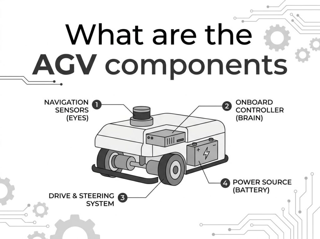
AGV Components: 逐個子系統細分
快速解答: What are the components of an AGV?
An automated guided vehicle is not a single machine but a stack of six interacting subsystems: 這 motion/drive system (BLDC servo motor + 行星齒輪箱 + drive wheel + 制動 + 編碼器), 這 控制系統 (可程式邏輯控制器 / 運動控制器), 這 navigation & perception system (LiDAR, IMU, markers), 這 safety system (laser scanner, bumper, e-stop, 斯托), 這 power system (LiFePO₄ battery + BMS + charger), 和 communication system (Wi-Fi / CANopen / EtherCAT). A seventh, application-specific load-handling module (fork, lift, conveyor) sits on top. Most AGV motors run under 國際電工委員會 60034-1 duty S3 or S4, so the motor’s continuous torque must cover the RMS torque of the duty cycle, not just the peak — a detail many component lists ignore.
頁面內容
切換1. What Is an AGV Vehicle? (Concept Definition)
一個 自動導引車 (自動導引車) is a driverless transport platform that moves materials along a route using onboard sensors, a controller, and a powered drive subsystem. 這 “成分” of an AGV are best understood as functional subsystems rather than a flat parts list — each subsystem has an interface (機械的, 電力, or data) to the others.
1.1 The six core subsystems
| Subsystem | 主要功能 | 關鍵組件 | Interface to Rest of Vehicle |
|---|---|---|---|
| 運動 / 駕駛 | Convert electrical energy into controlled wheel motion | BLDC/servo motor, 行星齒輪箱, drive wheel, holding brake, 編碼器, 馬達驅動器 | Receives torque/speed commands from controller; returns position/velocity feedback |
| 控制 | “Brain” — task execution, path planning, coordination | Main controller / 可程式邏輯控制器, 運動控制器, I/O modules, safety PLC | Sends commands to drive; reads nav, 安全, power status |
| Navigation & Perception | Locate vehicle, sense surroundings, detect obstacles | LiDAR, IMU, magnetic/QR/RFID sensors, vision camera, odometry encoder | Feeds position + obstacle data to control |
| 安全 | Protect people, equipment, and the AGV | Safety laser scanner, bumper, e-stop, warning lights, STO controller | Can override drive commands (decelerate / 停止) |
| 力量 | Store and deliver energy to all subsystems | LiFePO₄ battery, BMS, charger / wireless pad, PDU | Supplies 24/48 V bus; reports SOC/SOH to control |
| 溝通 | Exchange data with fleet, WMS/MES, chargers | Wi-Fi/Ethernet module, CANopen/EtherCAT bus, 5G modem | Carries task, status, and coordination messages |
| 負載處理 (7th, app-specific) | Carry / lift / transfer the payload | Fork, scissor lift, roller/belt conveyor, tow hook, jacking module | Actuated by control; load mass feeds back into drive sizing |
1.2 AGV vs. AMR: same components, different architecture weight
| 方面 | 自動導引車 (fixed-route) | AMR (autonomous) |
|---|---|---|
| Navigation basis | Magnetic tape, QR, reflector, 金屬絲 | LiDAR/vision SLAM, no fixed infrastructure |
| Compute load | 低的 (follow path) | 高的 (onboard mapping + dynamic planning) |
| Encoder resolution | 緩和 | 更高 (precise odometry for SLAM) |
| Drive subsystem | Identical motor/gearbox/wheel | Identical motor/gearbox/wheel |
| Safety controller | Zone-based | Often dual — safety PLC + dynamic field |
2. How the Components Work Together (工作原理)
An AGV is a closed control loop. The sequence below shows how the subsystems hand off to one another on a typical transport cycle:
- Task receipt — Communication system pulls an order from the fleet manager (WMS/MES) over Wi-Fi/EtherCAT.
- Route planning — Control system computes the path using the Navigation system’s current pose (LiDAR + IMU + encoder odometry).
- Motion command — Control sends torque/speed setpoints to the Motor Driver for each drive wheel.
- Power conversion — Power system delivers 24/48 V from the LiFePO₄ pack through the BMS and PDU to the driver.
- Electromechanical actuation — BLDC motor spins, the planetary gearbox multiplies torque, the drive wheel pushes against the floor (traction = μ·N).
- 反饋 & 安全 — Encoder and IMU report actual motion; the Safety system continuously monitors the protective field and can command an emergency stop (斯托) if a person enters it.
- Load handling — On arrival, the Load Handling module lifts/transfers the payload; status returns to the fleet manager via Communication.
3. The Drive / Motion Subsystem in Detail (Comparison Tables)
The drive subsystem is where most AGV performance — and most AGV failures — originate. It deserves more than a one-line “發動機 + 車輪” entry.
3.1 Drive wheel topologies
| Topology | How steering works | 最適合 | Motor/gearbox implication |
|---|---|---|---|
| Differential (2-車輪) | Speed difference between L/R wheels | Compact AMRs, 清潔機器人 | 2 identical servo motors, no steering actuator |
| Steering drive wheel | 駕駛 + steer integrated in one module | Forklift/tugger AGVs, heavy payload | 發動機 + 行星齒輪箱 + steering servo |
| Omnidirectional (Mecanum / omni) | Rollers at 45° enable lateral motion | Tight spaces, dock alignment | 4+ 電機, high controller complexity |
| Integrated wheel drive | 發動機 + 變速箱 + wheel in one unit | Standard pallet AGVs | Drop-in (例如. maxon MW500, ≤500 kg/drive) |
3.2 Motor technology options for the drive subsystem
| 馬達類型 | 電壓 | Typical torque | 效率 | AGV fit |
|---|---|---|---|---|
| 無刷直流電機 + 行星齒輪箱 | 24–48V | 5–50 N·m wheel | 85–92% | 通用型, best cost/performance |
| Integrated servo wheel drive | 30–48V | 11–24 N·m cont. | 80–88% | Compact pallet/AMR |
| 交流伺服 (iron-core torque) | 200/400 V | 1.3–240 N·m | 88–94% | Heavy direct-drive wheels |
| 步進機 + 變速箱 | 24–48V | Low–mid | 60–75% | 低成本, open-loop only |
4. 工程數據 & 標準
4.1 國際電工委員會 60034-1 duty cycles for AGV motors
AGV motors do not run at constant load. 每 國際電工委員會 60034-1:2022, most AGVs fall under S3 (intermittent periodic) 或者 S4 (with starting). Sizing must use RMS torque over the cycle, not nameplate continuous torque.
| IEC等級 | 熱行為 | AGV application match | Torque derating note |
|---|---|---|---|
| S1 | 連續的, steady-state temp | Conveyor-style AGV, 24/7 線 | None — rated = continuous |
| S2 | 短時, cools between runs | Batch transport, long idle | Can exceed S1 torque 1.5–2× briefly |
| S3 | 間歇性, little cooling between cycles | Goods-to-person AMR, pick-place | Depends on duty cycle % (ed) |
| S4 | Intermittent with starting losses | Frequent start-stop feeder AGV | Derate 10–20% vs S1 (start current heat) |
| S5 | Intermittent with electric braking | Ramp AGV with regen braking | Braking energy adds heat |
| S6 | Continuous periodic, load/unload | Rolling with idle periods | Motor keeps rotating, partial cooling |
4.2 Efficiency classes: IEC vs NEMA
| 國際電工委員會 60034-30-1 | 一氧化氮鎂 1 相等的 | Loss vs previous | AGV relevance |
|---|---|---|---|
| IE1 | 標準效率 | 基線 | Legacy only |
| 瀏覽器2 | 高效率 | −~15% loss | Minimum in some regions |
| 瀏覽器3 | NEMA Premium® | −~20% loss | Common AGV servo minimum |
| 瀏覽器4 | 超級高級 (IE4 rule 2027, 我們) | −~15% loss vs IE3 | Recommended for efficiency/runtime |
| IE5 | No NEMA equivalent yet | −~20% loss vs IE4 | Emerging, synchronous PM |
4.3 Core formulas for component sizing
4.4 Manufacturer reference data
| 製造商 / 模型 | Key spec | AGV relevance |
|---|---|---|
| maxon MW500 wheel drive | ≤500 kg/drive; 11.4–23.7 N·m cont.; 30–48V; IP54; 1024 cpt encoder | Compact integrated wheel drive for pallet/AMR |
| maxon IDX 56 | 471–794 mNm; 24/48 V; IP65; integrated EPOS4 positioning | High torque-density servo for AGV joints/wheels |
| Faulhaber DualGear (BX4 + GPT) | Ø32 mm; 1.1 N·m cont. / 7 N·m peak; ≤0.6° backlash; −30…120 °C | Dual-output compact drive for conveyor/wheel |
| Yaskawa Sigma-7 SGM7D | 1.3–240 N·m; 30–360 rpm; 24-bit encoder; 3.1 kHz bandwidth; 350% 超載; STO SIL3 | Direct-drive wheel / heavy AGV axis |
| SKF E2 deep-groove bearing | 30–50% lower friction than standard; up to IEC frame 355 | Reduces motor/wheel losses, extends life |
5. Component Configuration by Application (最佳應用)
| AGV type | 駕駛 | Navigation | Motor spec | Safety emphasis |
|---|---|---|---|---|
| Pallet/unit-load | Steering drive wheel | LiDAR/reflector | BLDC 15–25 N·m wheel | Scanner + bumper |
| Goods-to-person AMR | Differential | SLAM | Integrated 11–24 N·m | Dynamic field |
| Tugger | 操舵 + caster | Magnetic/QR | 高啟動扭力 (S4) | Tow-load braking |
| Forklift AGV | Dual steering wheels | Reflector + vision | AC servo 50–240 N·m | Stability + load sensor |
| Conveyor/roller AGV | Differential | RFID dock | Compact BLDC + DualGear | Dock-zone scanner |
6. How to Select AGV Components (Step-by-Step Selection Guide)
- Define the mission profile — payload, takt, route length, 年級, floor, shifts per day.
- Size the drive motor to RMS torque — use the S3/S4 formula; never size to peak only. 看看我們的 AGV motor torque calculation guide.
- Choose gearbox ratio — place the motor in its efficient speed band; confirm wheel speed at nominal voltage (看 AGV speed & RPM guide).
- Match navigation to route flexibility — fixed route → magnetic/QR; variable → LiDAR SLAM.
- Specify the power system — 48 V LiFePO₄ for heavier loads; size Ah from shift energy; plan charging (opportunity vs. swap). 我們的 效率 & 電池運轉時間 article has the model.
- Design the safety architecture — 國際標準化組織 3691-4; STO at SIL3/PL-e on the servo drives; scanner + bumper + e-stop.
- Verify thermal & ambient derating — apply the 40 ℃ / 50 °C factors; upgrade to Class F/H if needed.
7. 常見的工程錯誤
| 錯誤 | 結果 | 正確做法 |
|---|---|---|
| Sizing motor to peak, not RMS torque | Overheating in S3/S4 duty | Use RMS formula over full cycle |
| Ignoring ambient derating | Premature insulation failure in hot warehouses | Derate 10–25% above 40 ℃; use Class F/H |
| Under-specifying encoder resolution | Poor SLAM odometry, drift | Use ≥1000 cpt or 24-bit absolute |
| Mixing 24 V and 48 V subsystems | Extra DC-DC losses, complexity | Standardize on one bus (usually 48 V) |
| Skipping STO/SIL3 on servo drives | Fails ISO 3691-4 遵守 | Specify STO SIL3/PL-e as standard |
| Selecting navigation before route is fixed | Overpays for SLAM or under-performs | Fix route flexibility requirement first |
| Underestimating cable/harness losses | Voltage sag at wheel under load | Size conductors for I²R at peak current |
| No regen handling on ramps | Bus overvoltage, tripped drives | Add brake resistor or bidirectional charger |
8. 故障排除表 (問題 → 原因 → 解決方案)
| 問題 | 可能的原因 | 解決方案 | Subsystem |
|---|---|---|---|
| Motor overheats on shift | RMS torque > 額定; no derating | Re-size to RMS; improve cooling | 駕駛 |
| AGV drifts off path | Low encoder resolution / wheel slip | Higher-res encoder; traction check | Nav + 駕駛 |
| Battery dies before shift end | Capacity undersized vs. duty | Increase Ah or add opportunity charging | 力量 |
| Unexpected e-stop trips | Safety field mis-set or reflective surface | Re-tune scanner zones; check mirrors | 安全 |
| CAN/EtherCAT drops | EMI from motor cables | Shield + separate trays; ferrite cores | 溝通 |
| Controller loses WMS link | Wi-Fi dead zone | Add AP or 5G roaming | 溝通 |
| Wheel slips on grade | Insufficient traction / 力矩 | Higher torque or dual drive | 駕駛 |
| Lift jams under load | Motor undersized for payload | Re-size lift actuator | Load handling |
| Bus voltage sags under accel | Conductor too thin | Upsize harness; add local cap | 力量 |
| Slow settling after move | Low servo bandwidth / tuning | Use ≥3 kHz loop; auto-tune | 控制 + 駕駛 |
9. 常問問題
What are the main components of an AGV?
An AGV is built from six interacting subsystems: the motion/drive system (發動機 + 變速箱 + 車輪 + 制動 + 編碼器), the control system (可程式邏輯控制器 / 運動控制器), the navigation and perception system (LiDAR, IMU, markers), the safety system (laser scanner, bumper, e-stop, 斯托), the power system (LiFePO₄ battery + BMS + charger), and the communication system (Wi-Fi / 能 / EtherCAT). The load-handling module (fork, lift, conveyor) is the seventh, application-specific layer.
Which motor is used in AGV drive systems?
Most modern AGVs use 24–48 V BLDC servo motors paired with a planetary gearbox, or integrated servo wheel drives. For high-torque direct-drive wheels, iron-core torque motors (例如. Yaskawa SGM7D, 1.3–240 N·m) are used. 根據 IEC 60034-1, AGV duty is typically S3 or S4, so the motor’s continuous torque must exceed the RMS torque over the duty cycle.
What is the difference between AGV and AMR architecture?
Both share the same six subsystems, but AMRs add onboard compute for SLAM and dynamic path planning, replacing fixed-infrastructure navigation (magnetic tape, reflectors) with LiDAR/vision. This shifts architecture weight from the navigation sensor to the control/compute subsystem and usually raises encoder resolution and safety-controller requirements.
How is AGV component reliability specified?
Drivetrain components use IEC 60034-1 佔空比 (S1–S10) 和絕緣等級 (B/F/H/N). Motors are rated by continuous and peak torque at 25 °C 環境溫度, with derating at higher temperatures. Safety functions follow ISO 3691-4 / 國際電工委員會 61508, with STO at SIL3 / PL-e being standard on servo drives such as Yaskawa Sigma-7.
What voltage do AGV batteries use?
The dominant platforms are 24 V and 48 V DC lithium iron phosphate (LiFePO₄). 48 V is preferred for heavier payloads and longer takt because it halves current for the same power, reducing I²R losses in the cable harness and controller. Battery capacity of 100–500 Ah supports 8–12 h shifts.
How do I select AGV components as a complete system?
Define payload, 速度, 佔空比, and floor condition first; then size the drive motor to the RMS torque (not peak), choose a gearbox ratio that puts the motor in its efficient speed band, select a navigation method matched to route flexibility, and verify safety architecture (國際標準化組織 3691-4) and battery runtime against the shift profile.
10. Why Choose GreenSky for AGV Components?
24–48 V integrated servo wheel drives and motor+planetary-gearbox pairs sized to your RMS torque.
We quote IEC 60034-1 duty (S1–S6) and insulation class on every AGV motor datasheet.
力矩, 速度, and duty-cycle sizing support — start with how much torque an AGV needs.
11. Related AGV Guides
- 什麼是 AGV 及其工作原理? — pillar page for the whole cluster
- How AGV Drive Systems Work — deep dive on the motion subsystem
- 現代倉庫中使用的 AGV 類型 — matching vehicle to components
- AGV用電機 — motor selection fundamentals
- AGV 的 BLDC 與伺服電機 — drive technology comparison
- AGV 齒輪馬達與直驅電機
12. Authority References
標準, manufacturer technical documentation, and peer-reviewed research cited in this article: